báo cáo hóa học:" Hafnium metallocene compounds used as cathode interfacial layers for enhanced electron transfer in organic solar cells Keunhee Park1, Se" ppt
Bạn đang xem bản rút gọn của tài liệu. Xem và tải ngay bản đầy đủ của tài liệu tại đây (393.24 KB, 6 trang )
NANO EXPRESS Open Access
Hafnium metallocene compounds used as
cathode interfacial layers for enhanced electron
transfer in organic solar cells
Keunhee Park
1
, Seungsik Oh
1
, Donggeun Jung
1*
, Heeyeop Chae
2
, Hyoungsub Kim
3
and Jin-Hyo Boo
4
Abstract
We have used hafnium metallocene compounds as cathode interfacial layers for organic solar cells [OSCs]. A
metallocene compound consists of a transition metal and two cyclopentadienyl ligands coordinated in a sandwich
structure. For the fabrication of the OSCs, poly[3,4-ethylenedioxythiophene]:poly(styrene sulfonate), poly(3-
hexylthiophene-2,5-diyl) + [6,6]-phenyl C
61
butyric acid methyl ester, bis-(ethylcyclopentadienyl)hafnium(IV)
dichloride, and aluminum were deposited as a hole transport layer, an active layer, a cathode interfacial layer, and
a cathode, respectively. The hafnium metallocene compound cathode interfacial layer improved the performance
of OSCs compared to that of OSCs without the interfacial layer. The current density-voltage characteristics of OSCs
with an interfacial layer thickness of 0.7 nm and of those without an interfacial layer showed power conversion
efficiency [PCE] values of 2.96% and 2.34%, respectively, under an illumination condition of 100 mW/cm
2
(AM 1.5).
It is thought that a cathode interfacial layer of an appropriate thickness enhances the electron transfer between
the active layer and the cathode, and thus increases the PCE of the OSCs.
Keywords: organic solar cell, cathode interfacial layer, metallocene compounds.
Introduction
Organic solar cells [OSCs] have attracted attention due
to their unique advantages, such as easy processing, low
cost of fabrication of large-area cells, and mechanical
flexibility [1]. However, the efficiency of organic solar
cells is not sufficient for them to be used commercially.
Therefore, many methods, such as treatment and anneal-
ing, have been proposed to improve the device perfor-
mance [2]. Recently, the most efficient OSCs have been
fabricated based on the bulk-heterojunction concept, in
which conjug ated polymer s (electron donors) and ful ler-
enes (electron acceptors) form a three-dimensional net-
work with a large area of phase-separation interface.
When photons are absorbed by the organic materials,
electron-hole pairs with strong binding energy are gener-
ated. The excitons subsequently dissociate, forming free
carriers,whiletheydiffusetotheinterfacebetweenthe
electron donor and the acceptor. Then, these photogen-
erated holes and electrons transpo rt thr ough t he donor
and acceptor materials, respectively, toward the electro-
des, eventually resulting in a photocurrent [1-3].
One of the key issues in the development of high effi-
ciency OSCs is the need to increase the c harge carrier
transport between the active layer and the electrode.
Metal electrodes have also received attention in this con-
text.Thisisnotsurprisingconsidering the experience
with organic light emitting diodes, into which LiF was
introduced to enhance the solar cell performance [4].
Recently, several approaches involving the insertion of var-
ious thin layers, such as Cs
2
CO
3
, have been reported
which aim to improve the electron i njection properties
between the active layer and the electrode in light-emitting
devices [5].
In this work, we investigate the photovoltaic properties
of OSCs with hafnium metallocene compounds as the
cathode interfacial layer. A metallocene compound con-
sists of a transition metal and two cyclopentadie nyl
ligands coordinated in a sandwich structure. We used
poly(3-hexylthiophene) [P3HT] as the electron d onor
* Correspondence:
1
Department of Physics, Brain Korea 21 Physics Research Division, and
Institute of Basic Science, Sungkyunkwan University, Suwon, 440-746,
Republic of Korea
Full list of author information is available at the end of the article
Park et al. Nanoscale Research Letters 2012, 7:74
/>© 2012 Park et al; licensee Springer. This is an Open Access article distributed under the terms of the Crea tive Commons Attribution
License ( enses/by/2.0), which permits unrestricted use, distribution, and reproduction in any medium,
provided the original work is properly cited.
material and [6,6]-phenyl C
61
butyric acid methyl ester
[PCBM] as the electron acceptor to fabricate OSCs. A
thin layer of bis-(ethylcyc lopentadienyl) hafnium(IV)
dichloride [ECHD] was inserted between the active layer
and the cathode. The use of a hafnium metallocene com-
pound cathode interfacial layer improved the perfor-
mance of OSCs compared to that of OSCs without the
interfacial layer.
Experiments
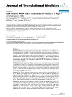
The structure of the solar cell and the chemical structure
of the ECHD are presented schematically in Figure 1. To
fabricate the OSCs, poly (styrene sulfonate)-doped poly
(3,4-ethylene dioxythiophene) [PEDOT:PSS] (26 nm), a
mixture of P3HT and PCBM (80 nm), ECHD (various
thickness), and aluminum [Al] (80 nm) were deposited on
the indium-tin-oxide[ITO] anode as a hole transport layer,
a photo active layer, and a cathode, respectively. The sub-
strates used in this study were commercially available
ITO-coated glass (Samsung Corning, Corning Inc., Corn-
ing, NY, USA) with an ITO film thickness of 1,425 Å and
a sheet resistance of 11.1 Ω/sq. First, the ITO glass was
cleaned successively in ultrasonic baths of trichloroethy-
lene, acetone, methanol, and deionized water for 1 0 min
each. A mixture of PEDOT:PSS and isopropyl alcohol
with a weight ratio of 1:2 was used for spin-coa ting. A
mixture of P3HT and PCBM (P3HT + PCBM) with the
optimized weight ratio of 1:1 was prepared with chloro-
benzene (4 wt.%). Thin films of PEDOT:PSS and P3HT +
PCBM were formed on the ITO-coated glass by spin-coat-
ing. The spin speed of the polymer film was 4,000 rpm for
PEDOT:PSS and 1,000 rpm for P3HT + PCBM. Then,
ECHD and Al were deposited on the P3HT + PCBM film
by thermal evaporation. The current density-voltage char-
acteristicsweredeterminedbyusingasolarsimulator
(Luzchem, LZC-SSR, Keithley 2400 SourceMeter, Kiethley
Instruments Inc., Cleveland, OH, USA) under sta ndard
conditions of air mass and 100 mW/cm
2
(AM 1 .5) at
room temperature. The absorbance spectra for the films
were measured using a UV-Visible [Vis] spectrophot-
ometer (Optizen 2120uvpuls, Mecasys Co., Ltd., Yuseong-
gu, Daejeon, South Korea) to determine the influence of
the ECHD layer on the absorption of the solar spectrum.
The surface roughness was determined by atomic force
microscopy [AFM] (ThermoMicroscopes Corporation,
Sunnyvale, CA, USA). Spectra were recorded on AXIS
NOVA (Kratos Inc., Chestnut Ridge, NY, USA) using a
He I (21.22 eV) source for ultraviolet photoelectron spec-
troscopy [UPS] analysis to investigate the electronic prop-
erties of the ECHD/Al structure. UPS spectra were
measured with the sam ple biased at -15 V to clear the
detector work function.
Result and discussion
The absorption spectra of ITO/PEDOT:PSS/(P3HT +
PCBM) structures with and without a cathode interfac ial
layer are shown in Figur e 2. Both samples showed good
absorption in th e visible range. The absorption spectrum
Glass
ITO (anode)
P3HT+PCBM
(active layer)
Al (cathode)
PEDOT:PSS (HTL)
ECHD
SMU
(
a
)
(
b
)
Figure 1 The structure of the solar cell and the chemical structure of the ECHD.(a) A schematic drawing of an organic solar cell structure
with a bis-(ethylcyclopentadienyl) hafnium(IV) dichloride cathode interfacial layer. (b) The chemical structure of the bis-(ethylcyclopentadienyl)
hafnium(IV) dichloride.
Park et al. Nanoscale Research Letters 2012, 7:74
/>Page 2 of 6
of the sample with the ECHD cathode interfacial layer was
similar to that without the ECHD layer.
The current density versus applied voltage [J-V] charac-
teristics of the organic solar cells with various thicknesses
of ECHD are shown in Figure 3 under illumination wit h
100 mW/cm
2
(AM 1.5). The device without the interfacial
layer was used as the control, and the device s are desig-
nated according to the thickness of the ECHD cathode
interfacial layer. The thickness of the ECHD cathode inter-
facial layer was varied between 0.5 nm and 2.0 nm. The
values characterizing the photovoltaic performances of the
OSCs, such as the short circuit current density [J
sc
], open
circuit voltage [V
oc
], fill factor [FF], and power conversion
efficiency [PCE], are given in Table 1. We see that the
interfacial ECHD layer at the cathode leads to an increase
of J
sc
from 8.38 to 10.5 mA/cm
2
. The highest PCE in this
set of experiments was 2.96% for the device with an
ECHD thickness of 0.7 nm.
Figure 4 shows the AFM images of the ITO/PEDOT:
PSS/(P3HT + PCBM) and ITO/PEDOT:PSS/(P3HT +
PCBM)/ECHD structures. The size of the s canned are a
was 2 μm×2μm. F or the sample without the ECHD
layer, the root mean square [RMS] roughness o f the su r-
face was 1.3 nm. However, the sample with the ECHD
layer had an RMS roughness of 0.8 nm. The film spikes,
which are thought to be caused during the heat treatment
after spin-casting, can ex ist in the P3HT + PCBM active
layer. If the metal cathode is dir ectly depo sited on to the
300 400 500 600 700 80
0
0.0
0.5
1.0
ITO/PEDOT:PSS/P3HT+PCBM
ITO/PEDOT:PSS/P3HT+PCBM/ECHD
Absorbance (a.u.)
Wavelen
g
th (nm)
Figure 2 UV-Vis absorption spectra of the ITO/PEDOT:PSS/(P3HT + PCBM)/ECHD and ITO/PEDOT:PSS/(P3HT + PCBM) structures.
0.0 0.2 0.4 0.6
-12
-8
-4
0
Current Density
O
mA/cm
2
P
Volta
g
e (V)
ECHD 0 nm
ECHD 0.5 nm
ECHD 0.7 nm
ECHD 1.0 nm
ECHD 2.0 nm
Figure 3 J-V characteristics of organic solar cells with various
thicknesses of the ECHD cathode interfacial layer. These are
taken under an AM 1.5 illumination of 100 mW/cm
2
.
Park et al. Nanoscale Research Letters 2012, 7:74
/>Page 3 of 6
active layer with the film spikes, an inhomogeneous distri-
bution of the electric field may occur at the P3HT:PCBM/
cathode interface. We guess, therefore, that the deposition
of an ultrathin cathode interfacial layer prior to the metal
cathode deposition may smoothen the interface and leads
to a more homogeneous distribution of electric field at the
P3HT:PCBM/cathode interface. As a result, when the
device is properly biased, a more even electron current
will flow between the active layer and the cathode, and
higher efficiency can thus be expected as reported by
Shrotriya et al. [6].
Figure 5a shows the UPS spectra at the secon dary elec-
tron cutoff. The cutoff energies, E
cutoff
, of Al and ECHD/
Al structures with ECHD thicknesses of 0.5, 0.7, 1.0, and
2.0 nm were found to be 4.12, 3.50, 3.12, 3.07, and 3.07
eV, respectivel y. It should be noted t hat the difference
between the E
cutoff
values of the ECHD/Al structures and
that of the Al layer was increased by the insertion of
ECHD. Figure 5b shows the UPS spectra of Al and
ECHD/Al structures with different ECHD thicknesses.
The UPS spectrum of the Al layer around the Fermi edge
was shifted to a higher binding energy by the presen ce of
the ECHD layer. All spectra shown in Figure 5b are verti-
cally shifted and plotted using a low scale to clearly display
the Fermi edge [7].
The spectra shown in Figure 5a, b illustrate the relation-
ships between the width of the spectrum, the sample work
function F, and the photon energy hν. By subtracting the
binding energy of the low energy cutoff from the high
binding energy edge of the UPS spectra, the work function
of the sample is obtained [8]. The change in the work
function of ECHD/Al for various ECHD thicknesses is
shown in Figure 6. As the ECHD thickness increased from
0to0.7nm,F decreased by as much as 0.50 eV. However,
further increasing t he ECHD thickness above 0.7 nm
increased the F values of ECHD/Al structures. In this
experiment, therefore, the minimum F value was found
for the ECHD (0.7 nm)/Al structure. In this structure, the
F value was decreased to 3.62 eV from the F of Al, which
is 4.12 eV.
A possible reason for this decrease of the work function
could be due to the hafnium [Hf] element contained in
the ECHD layer. The work function of Hf is reported to
be 3.9 eV, while Al is reported to have a F value in the
rangeof4.06to4.26eV[9].SuchasmallF value of the
Hf element compared to that of Al may have contributed
to a reduction of the work function of ECHD/Al structure
when the thickness of ECHD was increased up to 0.7 nm.
It seems that for ECHD layers with thicknesses over
0.7 nm, the F value of ECHD/Al system has less influence
from the Hf element. This finding suggests that an ECHD
Table 1 Characteristics of organic solar cells with
different thicknesses of the ECHD cathode interfacial
layer
OSCs J
sc
(mA/cm
2
) V
oc
(V) FF (%) PCE (%)
Control 8.38 0.62 45 2.34
ECHD 0.5 nm 9.43 0.59 45 2.46
ECHD 0.7 nm 10.5 0.61 46 2.96
ECHD 1.0 nm 9.7 0.60 43 2.52
ECHD 2.0 nm 7 0.59 51 1.77
OSCs, organic solar cells; ECHD, bis-(ethylcyclopentadienyl) hafnium(IV)
dichloride; J
sc
, short circuit current density; V
oc
, open circuit voltage; FF, fill
factor; PCE, power conversion efficiency.
(
a
)
(
b
)
Figure 4 The AFM images of (a) ITO/PEDOT:PSS/(P3HT + PCBM)/ECHD and (b) ITO/PEDOT:PSS/(P3HT + PCBM).
Park et al. Nanoscale Research Letters 2012, 7:74
/>Page 4 of 6
layer of proper thickness at the Al interface improves elec-
tron transport, possibly by lowering the work function of
the ECHD/Al structure compared to that of Al, resulting
in an enhanced performance of OSCs.
Conclusion
A metallocene compound (ECHD) that has one hafnium
and two cyclopentadienyl ligands coordinated in a sand-
wich structure was used as a cathode interfacial layer in
OSCs.Inthisstudy,wedemonstratedthatECHDcanbe
utilized as an efficient cathode interfacial layer in OSCs
basedonP3HT+PCBM.IntroductionoftheECHD
layer increased the OSC efficiency from 2.34% to 2.96%,
possibly resulting from a red uction of the work function,
leading to b etter electro n t ransport at the active layer/Al
interface. In our UPS experiment, the minimum work
function value of 3.62 eV was found for an ECHD/Al
structure with an ECHD thickness of 0.7 nm. It is
thought that the smoother surface of P3HT + PCBM
with ECHD compared to that of P3HT + PCBM without
an ECHD layer also helped to enhance the efficiency.
Acknowledgements
This work was supported by the grant NRF-2010-0029699 (Priority Research
Centers Program) and by the Basic Science Research Program through the
National Research Foundation of Korea (NRF) funded by the Ministry of
Education, Science and Technology (20100023316).
Author details
1
Department of Physics, Brain Korea 21 Physics Research Division, and
Institute of Basic Science, Sungkyunkwan University, Suwon, 440-746,
12345
He I 21.22 eV
2.0 nm ECHD/Al
1.0 nm ECHD/Al
0.7 nm ECHD/Al
Intens
i
ty
(
arb. un
i
ts
)
Kinetic Energy (eV)
Al
0.5 nm ECHD/Al
(a)
16 17 18 19 20 21 22
543210-
1
E
F
1.0 nm ECHD/Al
0.7 nm ECHD/Al
0.5 nm ECHD/Al
Al
2.0 nm ECHD/Al
He I 21.22 eV
Intensity (arb. units)
Kinetic energy (eV)
(b)
Binding energy (eV)
(
a
)
(
b
)
Figure 5 UPS spectra in the low kinetic and low binding energy regions.(a) UPS spectra in the low kinetic energy region from ECHD/Al
structures. The onset of secondary electrons for Al is shown by vertical bars. (b) UPS spectra in the low binding energy region from ECHD/Al
structures.
0.0 0.5 1.0 1.5 2.0
3.4
3.6
3.8
4.0
4.2
Work function (eV)
ECHD Thickness (nm)
Figure 6 Changes of work functions in the ECHD/Al structures.
These are measured from UPS measurements as a function of ECHD
thickness.
Park et al. Nanoscale Research Letters 2012, 7:74
/>Page 5 of 6
Republic of Korea
2
Department of Chemical Engineering, Sungkyunkwan
University, Suwon, 440-746, Republic of Korea
3
School of Advanced Materials
Science and Engineering, Sungkyunkwan University, Suwon, 440-746,
Republic of Korea
4
Department of Chemistry and Institute of Basic Science,
Sungkyunkwan University, Suwon 440-746, Republic of Korea
Authors’ contributions
The work presented here was carried out in collaboration among all authors.
KP, DJ, HC, HK, and JHB defined the research theme. KP and SO carried out
the laboratory experiments and analyzed the data. HC, HK, and JHB analyzed
the data and discussed the analysis. DJ designed the experiments and
discussed the analysis. KP and DJ wrote the manuscript. All authors read and
approved the final manuscript.
Competing interests
The authors declare that they have no competing interests.
Received: 7 September 2011 Accepted: 9 January 2012
Published: 9 January 2012
References
1. Kim K, Liu J, Namboothiry MAG, Carrol DL: Roles of donor and acceptor
nanodomains in 6% efficient thermally annealed polymer photovoltaics.
Appl Phys Lett 2007, 90:163511.
2. Padinger F, Rittberger RS, Sariciftci NS: Effects of postproduction treatment
on plastic solar cells. Adv Funct Mater 2003, 13:85-88.
3. Li G, Shrotriya V, Huang JS, Yao Y, Moriarty T, Emery K, Yang Y: High-
efficiency solution processable polymer photovoltaic cells by self-
organization of polymer blends. Nat Mater 2005, 4:864-868.
4. Brabec CJ, Shaheen SE, Winder C, Sariciftci NS: Effect of LiF/metal
electrodes on the performance of plastic solar cells. Appl Phys Lett 2002,
80:1288-1290.
5. Huang J, Xu Z, Yang Y: Low-work-function surface formed by solution-
processed and thermally deposited nanoscale layers of cesium
carbonate. Adv Funct Mater 2007, 17:1966-1973.
6. Shrotriya V, Wu EH-E, Li G, Yao Y, Yang Y: Efficient light harvesting in
multiple-device stacked structure for polymer solar cells. Appl Phys Lett
2006, 88:064104.
7. Park Y, Choong V, Gao Y, Hsieh BR, Tang CW: Workfunction of indium tin
oxide transparent conductor measured by photoelectron spectroscopy.
Appl Phys Lett 1996, 68:2699-2701.
8. Ertl G, Küppers J: Low Energy Electrons and Surface Chemistry Weinheim: VCH
Verlagsgesellschaft mbH; 1985.
9. CRC: In Handbook of Chemistry and Physics 75 edition. Edited by: Lide DR.
Boca Raton, FL: CRC; 1994:.
doi:10.1186/1556-276X-7-74
Cite this article as: Park et al.: Hafnium metallocene compounds used as
cathode interfacial layers for enhanced electron transfer in organic solar
cells. Nanoscale Research Letters 2012 7:74.
Submit your manuscript to a
journal and benefi t from:
7 Convenient online submission
7 Rigorous peer review
7 Immediate publication on acceptance
7 Open access: articles freely available online
7 High visibility within the fi eld
7 Retaining the copyright to your article
Submit your next manuscript at 7 springeropen.com
Park et al. Nanoscale Research Letters 2012, 7:74
/>Page 6 of 6