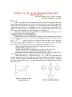
Hilux 2015 2018 manual 1gd ftv starting he thong khoi dong
Bạn đang xem bản rút gọn của tài liệu. Xem và tải ngay bản đầy đủ của tài liệu tại đây (2.41 MB, 57 trang )
Print-Toyota Service Information
11/3/17, 6(51 pm
Print
Exit
1GD-FTV STARTING ENGINE SWITCH(for RHD) COMPONENTS
ILLUSTRATION
*1
ENGINE SWITCH
*2
NO. 1 SWITCH HOLE BASE
© 2012 TOYOTA MOTOR CORPORATION. All Rights Reserved.
/>
Page 1 of 1
Print-Toyota Service Information
11/3/17, 6(52 pm
Print
Exit
1GD-FTV STARTING ENGINE SWITCH(for RHD) INSPECTION
PROCEDURE
89611
1.INSPECT ENGINE SWITCH
a.
Component without harness connected
(Engine Switch)
*a
Measure the resistance according to the value(s) in the table below.
Standard Resistance:
Tester
Switch
Specified
Connection
Condition
Condition
5 (SS1) - 6
(AGND)
1 (SS2) - 6
(AGND)
Not pushed
10 kΩ or
higher
5 (SS1) - 6
(AGND)
1 (SS2) - 6
(AGND)
Pushed
Below 1 Ω
If the result is not as specified, replace the engine switch.
b.
Apply battery voltage between the terminals of the engine switch, and check the illumination condition of
the engine switch.
OK:
Measurement
Specified Condition
Condition
Battery positive (+) →
Terminal 9 (SWIL)
Battery negative (-) →
Terminal 6 (AGND)
Illuminates
NOTICE:
·
·
If the positive (+) lead and the negative (-) lead are incorrectly connected, the engine switch
indicator will not illuminate.
If the voltage is too low, the indicator will not illuminate.
If the result is not as specified, replace the engine switch.
/>
Page 1 of 2
Print-Toyota Service Information
11/3/17, 6(52 pm
© 2012 TOYOTA MOTOR CORPORATION. All Rights Reserved.
/>
Page 2 of 2
Print-Toyota Service Information
11/3/17, 6(52 pm
Exit
1GD-FTV STARTING ENGINE SWITCH(for RHD) INSTALLATION
PROCEDURE
1.INSTALL ENGINE SWITCH
a.
89611
Attach the 2 claws to install the engine switch.
2.INSTALL NO. 1 SWITCH HOLE BASE
55446A
Click hereVehicle Interior>INTERIOR PANELS / TRIM>LOWER INSTRUMENT PANEL>REASSEMBLY
© 2012 TOYOTA MOTOR CORPORATION. All Rights Reserved.
/>
Page 1 of 1
Print-Toyota Service Information
11/3/17, 6(47 pm
Exit
1GD-FTV STARTING GLOW PLUG COMPONENTS
ILLUSTRATION
*1
GLOW PLUG ASSEMBLY
*3
GLOW PLUG SCREW GROMMET
*2
-
NO. 1 GLOW PLUG CONNECTOR
-
N*m (kgf*cm, ft.*lbf): Specified torque
-
-
© 2012 TOYOTA MOTOR CORPORATION. All Rights Reserved.
/>
Page 1 of 1
Print-Toyota Service Information
11/3/17, 6(47 pm
Exit
1GD-FTV STARTING GLOW PLUG INSTALLATION
CAUTION / NOTICE / HINT
NOTICE:
·
When replacing the parts in the following chart (A), replace the No. 1 injection pipe sub-assembly, No. 2
injection pipe sub-assembly and/or fuel inlet pipe sub-assembly with new ones.
Replaced Parts (A)
Pipes Requiring New Replacement
·
·
·
·
·
Common rail assembly
·
·
·
No. 1 injection pipe sub-assembly
No. 2 injection pipe sub-assembly
Fuel inlet pipe sub-assembly
After removing the No. 1 injection pipe sub-assembly, No. 2 injection pipe sub-assembly and/or fuel inlet
pipe sub-assembly, clean them with a brush and compressed air.
The common rail assembly is a precision instrument. Do not use the common rail assembly if it is struck
or dropped.
Hold the common rail assembly itself during removal and installation. Do not hold the pressure discharge
valve or fuel pressure sensor, etc.
Make sure foreign matter does not enter the fuel path.
PROCEDURE
1.INSTALL GLOW PLUG ASSEMBLY
19850
NOTICE:
·
·
·
a.
b.
Measure the resistance of the glow plug when reinstalling it. If the result is not as specified, replace the
glow plug with a new one.
Replace the glow plug with a new one when it has been dropped or subjected to a physical impact.
Remove any carbon deposits from the glow plug hole when reinstalling the glow plug.
Clean the glow plug hole.
i. Wrap tape around a drill bit with a diameter of 4.8 mm (0.189 in.), 108.7 mm (4.28 in.) from its tip.
ii.
Insert the drill bit 108.7 mm (4.28 in.) into the glow plug hole (up to the tape) and remove any carbon
deposits by turning the drill bit by hand.
iii.
Insert a drill bit with a diameter of 3.9 mm (0.154 in.) into the glow plug hole and remove any carbon
deposits from the end of the glow plug hole by turning the drill bit by hand.
Using a 10 mm deep socket wrench, install the 4 glow plug assemblies.
Torque:
17.5 N*m (178 kgf*cm, 13 ft.*lbf)
NOTICE:
Do not use any tools, such as air tools, which are liable to cause an impact to the glow plugs when
installing them.
2.INSTALL NO. 1 GLOW PLUG CONNECTOR
a.
19871
Temporarily install the No. 1 glow plug connector with the 4 nuts.
/>
Page 1 of 2
Print-Toyota Service Information
b.
Tighten the 4 nuts.
Torque:
2.2 N*m (22 kgf*cm, 19 in.*lbf)
c.
Install the 4 glow plug screw grommets.
d.
Using an E8 "TORX" socket wrench, install the stud bolt to the intake manifold.
Torque:
10 N*m (102 kgf*cm, 7 ft.*lbf)
3.INSTALL COMMON RAIL ASSEMBLY
11/3/17, 6(47 pm
23810A
Click hereEngine / Hybrid System>1GD-FTV FUEL>COMMON RAIL>INSTALLATION
4.CONNECT CABLE TO NEGATIVE BATTERY TERMINAL
NOTICE:
When disconnecting the cable, some systems need to be initialized after the cable is reconnected.
Click hereGeneral>INTRODUCTION>REPAIR INSTRUCTION>INITIALIZATION
© 2012 TOYOTA MOTOR CORPORATION. All Rights Reserved.
/>
Page 2 of 2
Print-Toyota Service Information
11/3/17, 6(47 pm
Exit
1GD-FTV STARTING GLOW PLUG ON-VEHICLE INSPECTION
PROCEDURE
1.CHECK GLOW PLUG
a.
Remove the glow plug connector.
Click hereEngine / Hybrid System>1GD-FTV STARTING>GLOW PLUG>REMOVAL
b.
Measure the resistance according to the value(s) in the table below.
Standard Resistance:
Tester
Specified
Condition
Connection
Condition
Glow plug
terminal Body ground
20°C (68°F)
Approximately
1.0 Ω
If the result is not as specified, replace the glow plug assembly.
NOTICE:
·
·
·
·
c.
Be careful not to damage the glow plug assemblies, as this may cause an open circuit or shorten
the life of the glow plug assemblies.
Do not allow oil or gasoline to contact the glow plug assembly when cleaning it.
Clean off any oil on the terminal with a dry cloth.
Do not apply more than 11 V to the glow plug assembly, as this may cause an open circuit.
Install the glow plug connector.
Click hereEngine / Hybrid System>1GD-FTV STARTING>GLOW PLUG>INSTALLATION
/>
Page 1 of 2
Print-Toyota Service Information
11/3/17, 6(47 pm
© 2012 TOYOTA MOTOR CORPORATION. All Rights Reserved.
/>
Page 2 of 2
Print-Toyota Service Information
11/3/17, 6(47 pm
Exit
1GD-FTV STARTING GLOW PLUG REMOVAL
CAUTION / NOTICE / HINT
CAUTION:
·
·
·
To prevent burns, do not touch the engine, exhaust manifold or other high temperature components
while the engine is hot.
To prevent burns, do not touch the engine, exhaust pipe or other high temperature components while
the engine is hot.
Make sure to wear protective gloves when performing work to avoid burns.
NOTICE:
·
When replacing the parts in the following chart (A), replace the No. 1 injection pipe sub-assembly, No. 2
injection pipe sub-assembly and/or fuel inlet pipe sub-assembly with new ones.
Replaced Parts (A)
Pipes Requiring New Replacement
·
·
·
·
·
Common rail assembly
·
·
·
No. 1 injection pipe sub-assembly
No. 2 injection pipe sub-assembly
Fuel inlet pipe sub-assembly
After removing the No. 1 injection pipe sub-assembly, No. 2 injection pipe sub-assembly and/or fuel inlet
pipe sub-assembly, clean them with a brush and compressed air.
The common rail assembly is a precision instrument. Do not use the common rail assembly if it is struck
or dropped.
Hold the common rail assembly itself during removal and installation. Do not hold the pressure discharge
valve or fuel pressure sensor, etc.
Make sure foreign matter does not enter the fuel path.
PROCEDURE
1. WARM UP ENGINE
CAUTION:
To protect the glow plug assembly from damage, before removing the glow plug assembly, make sure to warm
up the engine.
2.REMOVE COMMON RAIL ASSEMBLY
23810A
Click hereEngine / Hybrid System>1GD-FTV FUEL>COMMON RAIL>REMOVAL
/>
Page 1 of 3
Print-Toyota Service Information
3.REMOVE NO. 1 GLOW PLUG CONNECTOR
11/3/17, 6(47 pm
19871
CAUTION:
Make sure to wear protective gloves when performing work to avoid burns.
a.
Using an E8 "TORX" socket wrench, remove the stud bolt from the intake manifold.
b.
Remove the 4 glow plug screw grommets.
c.
Remove the 4 nuts and No. 1 glow plug connector.
4.REMOVE GLOW PLUG ASSEMBLY
19850
CAUTION:
Make sure to wear protective gloves when performing work to avoid burns.
/>
Page 2 of 3
Print-Toyota Service Information
11/3/17, 6(47 pm
a.
Using a 10 mm deep socket wrench, remove the 4 glow plug assemblies.
© 2012 TOYOTA MOTOR CORPORATION. All Rights Reserved.
/>
Page 3 of 3
Print-Toyota Service Information
11/3/17, 6(46 pm
Exit
1GD-FTV STARTING GLOW PLUG CONTROLLER COMPONENTS
ILLUSTRATION
*A
for LHD
*1
GLOW PLUG CONTROLLER
N*m (kgf*cm, ft.*lbf): Specified torque
*2
-
WIRE HARNESS
-
ILLUSTRATION
/>
Page 1 of 3
Print-Toyota Service Information
*A
for LHD
*1
*3
GLOW PLUG CONTROLLER
NO. 2 GLOW PLUG CONTROLLER BRACKET
N*m (kgf*cm, ft.*lbf): Specified torque
11/3/17, 6(46 pm
*2
-
NO. 1 GLOW PLUG CONTROLLER BRACKET
-
-
-
ILLUSTRATION
*A
for RHD
*1
GLOW PLUG CONTROLLER
*2
WIRE HARNESS
/>
Page 2 of 3
Print-Toyota Service Information
N*m (kgf*cm, ft.*lbf): Specified torque
11/3/17, 6(46 pm
-
-
ILLUSTRATION
*A
for RHD
*1
GLOW PLUG CONTROLLER
-
*3
NO. 2 GLOW PLUG CONTROLLER BRACKET
-
-
N*m (kgf*cm, ft.*lbf): Specified torque
-
-
*2
NO. 1 GLOW PLUG CONTROLLER BRACKET
© 2012 TOYOTA MOTOR CORPORATION. All Rights Reserved.
/>
Page 3 of 3
Print-Toyota Service Information
11/3/17, 6(46 pm
Exit
1GD-FTV STARTING GLOW PLUG CONTROLLER INSTALLATION
PROCEDURE
1.INSTALL NO. 2 GLOW PLUG CONTROLLER BRACKET
a.
Install the No. 2 glow plug controller bracket to the glow plug controller with the 2 screws.
Torque:
3.0 N*m (31 kgf*cm, 27 in.*lbf)
2.INSTALL NO. 1 GLOW PLUG CONTROLLER BRACKET
a.
28559A
28559
Install the No. 1 glow plug controller bracket to the glow plug controller with the 2 screws.
Torque:
3.0 N*m (31 kgf*cm, 27 in.*lbf)
3.INSTALL GLOW PLUG CONTROLLER
a.
for LHD:
i. Install the glow plug controller with the 2 bolts.
Torque:
8.0 N*m (82 kgf*cm, 71 in.*lbf)
b.
for RHD:
i. Install the glow plug controller with the bolt.
Torque:
8.0 N*m (82 kgf*cm, 71 in.*lbf)
c.
Connect the 4 connectors and attach the clamp.
28551
4.CONNECT CABLE TO BATTERY TERMINAL
NOTICE:
When disconnecting the cable, some systems need to be initialized after the cable is reconnected.
Click hereGeneral>INTRODUCTION>REPAIR INSTRUCTION>INITIALIZATION
© 2012 TOYOTA MOTOR CORPORATION. All Rights Reserved.
/>
Page 1 of 1
Print-Toyota Service Information
11/3/17, 6(46 pm
Exit
1GD-FTV STARTING GLOW PLUG CONTROLLER REMOVAL
PROCEDURE
1. PRECAUTION
NOTICE:
After turning the ignition switch off, waiting time may be required before disconnecting the cable from the
battery terminal. Therefore, make sure to read the disconnecting the cable from the battery terminal notice
before proceeding with work.
Click hereGeneral>INTRODUCTION>REPAIR INSTRUCTION>PRECAUTION
2.DISCONNECT CABLE FROM BATTERY TERMINAL
NOTICE:
When disconnecting the cable, some systems need to be initialized after the cable is reconnected.
Click hereGeneral>INTRODUCTION>REPAIR INSTRUCTION>INITIALIZATION
3.REMOVE GLOW PLUG CONTROLLER
28551
a.
for LHD:
i. Disconnect the 4 connectors and detach the clamp from the glow plug controller.
ii.
Remove the 2 bolts and glow plug controller.
/>
Page 1 of 2
Print-Toyota Service Information
11/3/17, 6(46 pm
b.
for RHD:
i. Disconnect the 4 connectors and detach the clamp from the glow plug controller.
ii.
Remove the bolt and glow plug controller.
4.REMOVE NO. 1 GLOW PLUG CONTROLLER BRACKET
a.
Remove the 2 screws and No. 1 glow plug controller bracket from the glow plug controller.
5.REMOVE NO. 2 GLOW PLUG CONTROLLER BRACKET
a.
28559
28559A
Remove the 2 screws and No. 2 glow plug controller bracket from the glow plug controller.
© 2012 TOYOTA MOTOR CORPORATION. All Rights Reserved.
/>
Page 2 of 2
Print-Toyota Service Information
11/3/17, 6(52 pm
Exit
1GD-FTV STARTING IGNITION SWITCH COMPONENTS
ILLUSTRATION
*1
IGNITION SWITCH ASSEMBLY
*3
●
TAPERED-HEAD BOLT
Non-reusable part
*2
-
STEERING LOCK ACTUATOR OR UPPER
BRACKET ASSEMBLY
-
© 2012 TOYOTA MOTOR CORPORATION. All Rights Reserved.
/>
Page 1 of 1
Print-Toyota Service Information
11/3/17, 6(53 pm
Exit
1GD-FTV STARTING IGNITION SWITCH INSPECTION
PROCEDURE
1.INSPECT IGNITION SWITCH ASSEMBLY
*a
a.
84450
Component without harness connected
(Ignition Switch Assembly)
Measure the resistance according to the value(s) in the table below.
Standard Resistance:
Tester
Switch
Specified
Connection
Condition
Condition
-
LOCK
10 kΩ or
higher
7 (ACC) - 5
(AM1)
ACC
Below 1 Ω
8 (IG1) - 5
(AM1)
7 (ACC) - 5
(AM1)
4 (AM2) - 3
(IG2)
ON
Below 1 Ω
8 (IG1) - 5
(AM1)
6 (ST1) - 5
(AM1)
4 (AM2) - 3
(IG2)
4 (AM2) - 2
(ST2)
START
Below 1 Ω
If the result is not as specified, replace the ignition switch assembly.
© 2012 TOYOTA MOTOR CORPORATION. All Rights Reserved.
/>
Page 1 of 1