Radio Frequency Identification Fundamentals and Applications, Design Methods and Solutions Part 9 ppt
Bạn đang xem bản rút gọn của tài liệu. Xem và tải ngay bản đầy đủ của tài liệu tại đây (7.36 MB, 25 trang )
Radio Frequency Identification Fundamentals and Applications, Design Methods and Solutions
192
Fig. 11. Signal in the winding of the tag.
Fig. 12. Signal in the reader after the demodulation in the first lock-in amplifier.
Figure 13 shows the signal after the second lock-in amplifier. It has the same frequency that
the signal produced by the microchip in the tag. It means that a signal with the same
frequency that the produced in the PIC of the tag has successfully obtained in the reader.
Fig. 13. Signal in the reader after the demodulation in the second lock-in amplifier.
These graphs (Figures 11, 12 and 13) clearly show that the microcontroller in the tag can be
powered by a low frequency magnetic field and it can send information. They also show
that the fluxgate with the second in-phase demodulation has successfully used as a reader.
3.4 Theoretical model
In (Ciudad Rio-Perez et al., 2008) it is given an accurate model to calculate the distance
limitation of the ULF RFID system for a particular application. The model is also compared
RFID in Metal Environments: An Overview on Low (LF) and Ultra-Low (ULF) Frequency Systems
193
with experimental data. This distance limitation can be due to failures in the detection or in
powering the tag.
3.4.1 Detection of the tag: minimum sensitivity of the reader (fluxgate sensor).
The magnetic field in the tag position H
ex
is assumed to be sinusoidal with amplitude H
0
and angular frequency ω:
(5)
The magnetic flux through the tag and the induced e.m.f. in the winding are easily
calculated. See (Ciudad Rio-Perez et al., 2008) for a detailed deduction. This e.m.f. is used to
charge the capacitors that power the microcontroller. When the PIC in the tag short-circuits
the winding, the induced e.m.f. gives rise to the flow of a current through the winding. This
current causes a magnetic field. The total magnetic field (H
R
) that magnetizes the magnetic
core of the tag is the addition of the magnetic fields produced by the antenna (H
ex
) and the
winding (H
tag
). The total magnetic field is:
(6)
R is the resistance of the winding of the tag and L its inductance. When the microcontroller
opens the winding, R=∞ and the magnetization of the magnetic core of the tag is given by:
(7)
χ
is the magnetic susceptibility of the magnetic core. However, when this winding is
shortcircuited, the magnetic core is not magnetized because R=0 and then H
R
=0. Therefore,
being V the volume of the magnetic core, the change in the magnetic moment of the tag is
given by:
(8)
If a shielding layer of thickness t
s
, conductivity σ and magnetic permeability μ
S
is placed
between the excitation system and the tag, the magnetic field is attenuated according the
Skin’s formula (5):
(9)
The tag is supposed to behave like a magnetic dipole. It implies that the magnetic field
produced by the tag is reduced with the cube of the distance to the tag. This behaviour has
been experimentally checked. See Figure 13.
The change of the magnetic field ΔH
tag
when opening and short-circuiting the winding, at a
distance r
t
along its axis and at the other side of the shielding wall, is given by:
Radio Frequency Identification Fundamentals and Applications, Design Methods and Solutions
194
Fig. 13. Change of the signal in the pickup winding of the fluxgate V
fluxgate
when opening and
short-circuiting the winding of the tag as a function of the distance between the tag and the
fluxgate. Notice that V
fluxgate
∝ ΔH
tag
. The relation V
fluxgate
-1
∝ d
tag-fluxgate
3
is characteristic of the
dipolar behaviour.
(10)
This expression gives the minimum sensitivity of the fluxgate sensor that is needed in order
to detect the tag at a distance r
t
and through the shielding. This expression is in good
accordance with our experimental measurements (Ciudad Rio-Perez et al., 2008).
3.4.2 Powering of the tag
Using any low-power microcontroller like a PIC16F84 from Microchip (working parameters:
ε = 2 V and I = 15 μA at 32 kHz), the main limitation of the system is the maximum distance
at which the induced e.m.f. in the tag is able to power its electronics. The r.m.s. value of the
e.m.f. in the tag is given by:
(11)
Formula (11) is in good accordance with the experimental values (Ciudad Rio-Perez et al.,
2008). This simple model allows a proper design of the new RFID system for a particular
application. Any particular arrangement of metals can be modelized by using an effective
theoretical shielding.
RFID in Metal Environments: An Overview on Low (LF) and Ultra-Low (ULF) Frequency Systems
195
4. Conclusions
Inductive coupling-based systems show different problems to work in the presence of
metals. The low frequency (LF) systems can work with metals in the surroundings.
However, they only can work through metals in some particular circumstances and designs.
The different problems arising from metal non-cleaned surroundings have been showed in
section 2. All these problems could be avoided if the working frequency is reduced.
However, the inductive coupling becomes inefficient quickly.
We have developed and experimentally tested a new system to work through metals. It is
shown in Section 3. It works at ultra low frequencies (1 - 100 kHz) and through metals. The
new RFID system works without any resonant circuit. It is based on measuring changes of
the magnetization of a magnetic core included in the tag. Different geometrical
arrangements for the antenna and the reader have been designed. This is of importance
since the magnetic fields produced by these antennas have different directions in the
position of the tag. The characteristics of the antennas can be checked in (Ciudad et al., 2004)
and (Ciudad Rio- Perez et al., 2008). A combination of those antennas will allow to avoid
any directional problem. In addition, we give a theoretical model of the system. It allows a
better design of the system for any particular application.
In section 3.4 it is explained a theoretical model of the system. According to this model and
our experimental data, the work distance is bellow 0.4 m for a typical antenna and low
intensity magnetic fields. The system has demonstrated to be able to work through
aluminium layers with thicknesses up to 0.2 mm and in close contact to the tag.
Table 1 summarizes the characteristics of LF and ULF systems. The comments are relative to
the different RFID systems. Some similar tables for other RFID systems can be found in
(Wilding & Delgardo, 2004) and references therein.
5. References
Aroca, C.; Prieto, J.L.; Sanchez, P.; Lopez & Sanchez, M.C. (1995). Spectrum analyzer for low
magnetic field, Review of Scientific Instruments, 66, (1995) 5355-5359
Balanis, C.A. (1997). Antenna theory: analysis and design (2nd). John Wiley & Sons Publisher,
0- 471-59268-4, New York
Bovelli, S.; Neubauer, F. & Heller. (2006). C. A novel antenna design for passive RFID
transponders on metal surfaces, Proceedings of the 36th European Microwave
Conference, pp 580-582, September 2006, Manchester UK
Bottomley, P.A. & Andrew, E.R. (1978). RF field penetration, phase shift and power
dissipation in biological tissue: implications for NMR imaging, Phys. Med. Biol. 23
(1978) 630-643.
Bowler, N. & Huang, Y. (2005). Electrical conductivity measurmement of metal plates using
broadband eddy-current and four-point methods. Measurement Scientific Technology.
16 (2005) 2193-2200
Ciudad, D.; Perez, L.; Sanchez, P.; Sanchez, M.C.; Lopez, E. & Aroca, C. (2004). Ultra low
frequency smart cards, Journal of electrical engineering, 55, 10/S, (2004) 58-61.
Ciudad Rio-Perez, D.; Arribas, P.C.; Aroca, C. & Sanchez, P. (2008). Testing thick magnetic
shielding effect on a new low frequency RFIDs sytem. IEEE Transaction on Antennas
and propagation, 56, 12 (December 2008) 3838-3843
Dixon, P.F.; Carpenter, M.P.; Osward, M.M. & Gibbs, D.A. (2007). RFID Tags, US Patent
7205898, April 17 2007
Dixon, P.F.; Carpenter, M.P.; Osward, M.M. & Gibbs, D.A. (2008). RFID tags having improved
read range, US Patent 7378973, May 27 2008
Radio Frequency Identification Fundamentals and Applications, Design Methods and Solutions
196
ULF System LF Systems
Physical principle
Fluxgate magnetometry Inductive coupling
Work frequency
1 kHz-100 kHz 125-134 kHz
Range
<0.4m (non-resonant
configuration)
< 1m
Size issues
Small size (due to the use of
fluxgates)
Large size
Data transfer rate
Very slow Slow
Metals: in the
surroundings
No problem
No problem (some design
issues)
Metals: wrapping the tag
No problem. Distance
range reduced
Only under very particular
circumstances
Prize: Antenna
High High
Prize: Tag
High (since it contains
magnetic material)
Low
Sensors
The tag can power sensors
connected to it as well as
send the measurements.
Sensors cannot be powered
by the RFID system
Applications
Any system having
problems with metals and
no high data transfer ratio
requirements.
Animal tracking. Item
tracking. Product
indentification. Car key.
Table 1. Comparison of the characteristics of LF and ULF systems.
Dobkin,D.M. & Weigan S.M. (2005) Enviromental effects on RFID tag antennas, 2005 IEE
MTT-S International Microwave Symposium Digest, pp. 135-138, 0-7803-8845-3, June
2005, Long Beach-California, IEEE
EM Microelectronic. (2002). AppNote 411: RFID Made Easy. EM Microelectronic - Marin SA,
September 2002
Finkenzeller, K. (2003). RFID Handbook (2nd), John Willey & Sons Publishers, 0-470-84402-7,
West Sussex
Hoeft, L.O. & Hofstra J.S. (1988). Experimental and theoretical analysis of the magnetic field
attenuation of enclosures, IEEE Transactions on electromagnetic compatibility, 30, 3
(August 1988), 326-340, 0018-9375
Ida, N. & Bastos, J.P.A. (1997). Electromagnetics and calculations of fields (2
nd
), Springer-Verlag,
ISBN 0-387-94877-5, New York
Lide, D R. (ed.). (2009). CRC Handbook of Chemistry and Physics, 89th Edition (Internet version
2009), CRC Press, Taylor and Francis, Boca Raton, F.L.
Perez, L.; de Abril, O.; Sanchez, M.C.; Aroca, C.; Lopez, E. & Sanchez, P. (2000).
Electrodeposited amorphous CoP multilayers with high permeability, Journal of
magnetism and magnetic materials, 215-216 (2000) 337-339
Perez, L.; Aroca, C.; Sanchez, P.; Lopez, E. & Sanchez, M.C. (2004). Planar fluxgate sensor
with an electrodeposited amorphous core, Sensors Actuators A, 109 (2004) 208-211
Ripka, P. (ed.) (2001). Magnetic sensors and magnetometers, Artech House Inc., 1-58053-057-5,
Norwood
Wilding, R. & Delgardo, T. (2004). RFID demystified: Part 1 The technology, benefits and
barriers to implementation, Logistic & Transport Focus, 6, 3 (2004) 26-31
12
Development of Metallic Coil Identification
System based on RFID
Myunsik Kim
1
, Beobsung Song
2
, Daegeun Ju
2
,
Eunjung Choi
2
, and Byunglok Cho
2
1
Sogang Institute of Advanced Technology(SIAT), Sogang Univ.
2
Ubiquitous Gwangyang & Global IT Institute,
Republic of Korea
1. Introduction
Recently, RFID gains increasing attention, since RF signal can eliminates the need an optical
line of sight and transmits relatively large amount of information from several tens of tags in
real time (Finkenzeller, 2003) (Landt. 2001). Based on these advantages, RFID is applied in
various fields. For example, RFID is widely spreading on products identification in logistics
and distribution fields instead of barcode (Chawla & Ha, 2007). The bus card and RF pass
are famous applications of RFID. Also, the development of special tags such as metallic tag
widens the applicable fields of RFID (Nikitin & Rao, 2006) (Kim et al, 2005). Among the
RFID applications, this paper focuses on the RFID technique for the SCM (Supply Chain
Management) regarding an iron and steel industry. Specially, the RFID based steel coil
identification system during a crane operation is developed. Since the iron and steel
industry is key industry providing material to other industries, it has no small effect.
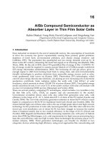
The system is developed for two purposes as follows. Nowadays, many factories employ
sophisticated machinery that automates many kinds of process. However, some processes
such as the quality checking, packaging, loading / unloading products to freight vehicle,
and so on are still dependent upon the workers, who encounters danger under the
automated system. The more the industrial field becomes automated, the more the field is
dangerous. Thus, the developed system ensures safety of workers by releasing them from
the products identification and checking checking process. Also, the automated product
identification system improves the efficiency of the manufacturing and distribution process
by preventing missing or mixing of products.
One of technical challenges associated with the RFID based coil identification is to apply the
system to the existed automated system while sustaining the identification performance
easily affected by environmental conditions such as reflection, refraction, and scattering of
RF signal from metallic surface of coils, crane and equipments. To cope with the problem,
two key techniques are proposed in this paper. First, the effective tag attachment method is
proposed considering the shape and properties of metallic coils, and working environment.
Second, robust reader antenna system is proposed to identify tag attached inside coil
efficiently. An antenna case is developed to reduce the effect from the attached surface and
improve tag identification performance by control beam pattern of the antenna.
Radio Frequency Identification Fundamentals and Applications, Design Methods and Solutions
198
To verify validity of the proposed system, simulation is performed using MWS 2008 EM
simulator and test using various model coils in laboratory. The experimental results in real
industrial environment in POSCO show that The coil is identified very successfully using
the proposed system.
This paper is organized as follows. In chapter II, the necessity of metallic coil identification
system in POSCO and first development is described. Experiment results using the
developed system and its problems are shown in Chapter III. Chapter IV shows the further
improvement of the RFID system and its simulation and experimental results are shown in
Chapter V. Finally, conclusions are drawn in chapter VI.
2. RFID based coil identification system
2.1 Background of the research
In POSCO, the products such as metallic coil are packaged and banded after manufactured
and stored until delivered to customer. Since the coil is heavy over several tons, cranes are
used to move the coil as showing in Fig. 1. The crane is automated then it is important to
manage the coil information correctly while it is moved. Currently, the coil Information is
managed using the stored position in warehouse. In general, the information is correct,
however, if there is error in the coil manufacturing schedule or sensed location of the crane,
coils are lost or mixed. Thus, sometimes, wrong coil is delivered to customers, it cause
problem in time, cost, and credit.
For the problem, a barcode label with product code, size, weight and etc is attached to a coil
and workers check the information periodically. The barcode is printed tag with several
vertical lines. In order to read the barcode, workers should come close and align reader and
barcode for scanning the lines with laser light. It spends much time to read barcode one by
one. Also, the printed barcode is easily stained or injured, it prevent from reading the stored
data in the barcode.
For the problem, the RFID based coil identification system is proposed. An RF tag is
attached to coil, which is identified using reader antenna installed to the crane and the
information is transferred to MES (Manufacturing Execution System) server. Even though
the coil storing map information is incorrect, it is fixed automatically when crane picks up
the coil without any effort of workers.
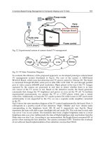
Fig. 1. The management of coil after manufacturing
Development of Metallic Coil Identification System based on RFID
199
2.2 Overview of developed system
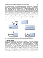
Fig. 2 shows the overview of proposed system. RF tag is attached to inside of a coil, which is
identified using reader antenna installed to crane shoe. The identified information is
transmitted to MES server through TCP/IP interface then the real time sensing and tracking
of a coil under the crane operation is available.
Fig. 2. Overview of developed system
However, since the coil and the neighboring equipments including crane are metallic object,
the identification performance of the RFID system is lowered affected by the environmental
effect. Also, in order to install the developed system in existing automated system without
any changes, the system should be satisfy the conditions as follows.
1. The identification performance should be unchanged under the environment conditions
surrounded by metallic object such as coil, crane, and other equipments.
2. The reader should read target tag only among neighboring tags.
3. The system is possible to be installed to current crane without any changes.
4. The tag should be cheap and light.
RFID system used in the developed system is shown in table 1. More detailed is described in
following section.
Tag UPM raflatac Dogbone Type
Reader Alien ALR-9900 reader
Reader Antenna Ceramic Patch Antenna
Interface to MES TCP/IP
Tag on metallic surface Flag tag technique
Table 1. RFID system applying in the developed system
Radio Frequency Identification Fundamentals and Applications, Design Methods and Solutions
200
(a) Nox-TM4 Metal Tag
SimplyRFID Corp.
(b) P0106AT Metal Tag
Sontec Inc
(c) Flag Tag
UPM Raflatac
Fig. 3. UHF RFID tag for metallic surface
2.3 Tag on metallic surface
Fig. 3 shows the tags can be used on metallic surface. Fig. (a) and (b) show metal tag, special
tag that can be read, even though it is attached on metallic surface. Tag antenna is printed
on a ferroelectric material such as ceramic with thickness of several millimeters. The basic
principle of the metal tag is shown in Fig. 4. Wireless communication of RFID becomes
possible by electromagnetic flux penetrating between two antennas of reader and tag as
shown in Fig. 4-(a). However, when a metal is close to tag antenna, eddy current caused by
reader’s magnetic field is generated and it cancels the magnetic field necessary for
communication as shown in Fig. 4-(b). When ferroelectric material is inserted between tag
antenna and metal surface as shown in Fig. 4-(c), the material concentrates magnetic flux
then the flux can flows without loss (Kim et al, 2005). Then the communication distance is
improved as results. However, the price of the metal tag is much expensive than ordinary
tag printed on film such as PI. Also, the metal tag is heavy then it comes off from the
attached surface by vibration more easy comparing with ordinary tag while a tag attached
object is moved. The cost and weight of the metal tag is chief obstacle to be applied.
(a) Normal Communication
Condition
(b) Communication condition
with a metal surface in a
vicinity
(c) Communication Condition
with ferroelectric sheet
present
Fig. 4. Basic principle of metal tag
Development of Metallic Coil Identification System based on RFID
201
Thus, the flagtag technique proposed by UPM is used in the developed system (Victor et al,
2006). Note that there is enough space between tag antenna and attached surface, the RF
communication is available. Flagtag technique is very simple idea that makes space between
tag and attaching surface. Fig 3-(c) shows the flagtag using label sticker. A tag is inserted in
label and the tag is stood by folding the label as shown in the figure. Since general cheap
film type tag can be used attaching on surface of various materials such as metal, paper, and
so on with the flagtag technique, it has advantage in cost and applicability.
Fig. 5. Tag used in the system
Fig. 5 shows the tag used in the developed system. A UPM dogbone type UHF ranged RFID
tag sized of 93 ×23 mm is used in paper label. The tag is erected by folding the paper label as
shown in lower of Fig. 5. When the tag is attached, the identification performance is varied
according to the distance d between the tag and the attached surface. Fig. 6 shows the strength
of RF signal transmitted from the tag varied according to the distance d. As shown in the
figure, the strength is almost same with normal condition when the distance is over 2 cm.
Fig. 6. Power of transmitted RF signal according to the distance d
Radio Frequency Identification Fundamentals and Applications, Design Methods and Solutions
202
2.4 RFID reader and antenna
ALR-9900 UHF RFID reader of Alien technology corp. is used in the developed system. In
order to install reader in current crane, the smaller reader is better. Also, two more antenna
port is required to install antennas to two crane shoe of a crane. Since the MES server is far
from crane and it is hard to use wireless communication in factory environment, TCP/IP
communication interface is required to transmit data without any loss. Table 2 shows the
reader that can satisfy the above conditions.
Name ALR-9900 SRU-FK0100
Photo
Manufacturer Alien Technology Corp. Samsung Techwin
Tag Protocol
EPC Gen2
ISO18000-6c
EPC Gen2
ISO18000-6(TypeB)
Frequency 902.75~927.25 MHz 910-914 MHz
Size
190×160×40 mm 140×110×26 mm
Antenna Ports 4 Ports 4 Ports
I/F RS-232, TCP/IP RS-232, TCP/IP
Table 2. Specification of RFID readers
The specification of two readers is similar. Comparing with the Alien reader, SRU-FK0100 of
Samsung Techwin has an advantage in size. However, the SRU-FK0100 reader affect to
another sensor installed in crane then causes error in crane operation. After install the reader
to crane and attach two antennas to crane shoe, the operation of folding and unfolding the
shoe becomes unavailable. There is no reason to make the phenomena, since all sensors in
the crane are shielded and the reader satisfies the standard of RFID reader specification.
Fig. 7 shows the noise transmitted from the antenna port of the two RFID readers. The noise
level of two reader is under the standard. However, as shown in the figure, SRU-FK0100
reader has more noise than the ALR-9900 reader. It is regards as the reason that causes the
crane to malfunction. Since the industrial field with many sensors for automation can be
easily affected by any kinds of RF signal, the reader with less noise is better.
A Ceramic patch antenna sized of 80mm×7 mm is used with the ALR-9900 reader. Fig. 8
shows the antenna attached to crane shoe. Since the available width of the crane shoe is 12
cm only, the antenna is determined considering the required space for packaging. The
antenna has gain of 2~2.5 dBi and can detect a tag of 6 m away with the ALR-9900 reader.
To check the identification performance in real environment, we perform test in POSCO.
Detailed experimental results are shown in following section.
Development of Metallic Coil Identification System based on RFID
203
909.5~910MHz 914~914.5 MHz 914.5~1000 MHz
ALR-9900
SRU-FK0100
Fig. 7. Noise according to various frequency range
Fig. 8. Reader antenna attached to crane shoe
3. Experiment results
Fig. 9 shows the tag and antenna attached to coil and crane shoe. Label with tag is folded
and attach inside of the coil parallel to the coil plane. In order to avoid damage, the label is
put on 50 cm inner from the coil plane. Reader antenna is protected by plastic package and
attached to crane shoe as shown in the figure. Fig. 10 shows the coil identification process
when crane picks up the coil.
When the crane arm is down to pick up target coil, the tag inside the coil is identified using
the antenna in the crane shoe. The identified information is transmitted to MES server and
compared with the coil information in the storing map. If the two information are same, the
crane lifts up the coil. Table 3 shows the experimental results using the developed system.
Radio Frequency Identification Fundamentals and Applications, Design Methods and Solutions
204
Fig. 9. (upper) Tag attached inside of coil, (lower) Antenna attached on crane shoe
(a) (b)
(c) (d)
Fig. 10. Coil identification process using developed system while crane operation
(a) Crane arm is down to pick up target coil (b) Tag is identified,
(c) Unfolding crane shoe, (d) Lift up the coil
Development of Metallic Coil Identification System based on RFID
205
Day 1st 3rd 5th 7th
No. of Manufactured Coils with tag 440 429 511 505
Identify wrong coil 4 9 9 6
Error
Missing 1 5 16 40
Error rate (%) 1.1 3.3 4.9 9.1
Table 3. Test result of coil identification
Tags issued following the production schedule is attached to a coil during packaging
process and the coil is moved to warehouse using crane. Three cranes are selected for the
test such as crane used for moving coils to warehouse, and in warehouse and to freight
vehicle for shipment.
To test with as many tag attaced coils in the warehouse as possible, the test is performed
during a week. As shown in the results, the fail rate increases. It is caused by the increasing
the neighboring tags in the warehouse. First day, there are tags issued in the day then the
reader can identify the target tag only. However, the error rate increases in 3d day. The tag
behind the antenna is read by the back-radiation of RF signal. To solve the problem, we
reduce the RF signal transmission power. It is resulted that the missing rate increases. When
the power increases, the neighboring tags are detected together, and power decreases, the
reader can not detect the target tag. Also, the tag is attached parallel to the coil plane, the tag
lies down by the distortion caused by the effect of the curved surface of the coil. As the tag
comes close to metallic surface of the coil, the identification performance is lowered, then
the identification fail rate increases. For the problem, the developed system is improved in
two directions. It is shown in following section.
4. Improvement of developed RFID based coil identification system.
In this paper, the developed RFID based coil identification system is improved in two
directions: change of the tag attaching method and development of reader antenna package
to control the beam pattern of RF signal transmitted from the antenna.
4.1 Tag attachment method.
First, the tag attachment method is changed. Fig. 11-(a) shows the previous method that the
tag is attached parallel to the coil plane. In the case, since the lower paer of the label is
straight, the tag is distorted by the curved surface of the coil. This problem can be solved by
making the lower part of the tag curve fitted with the coil. However, the tag attachment
process becomes complicated and the label should be made in various shapes according to
the coil size. In addition, since the size of the tag shown in the coil plane is maximized with
the attachment method, the tag is easily broken during the banding process and effect of
wind passing through the coil.
For the problem, the tag attachment method is changed to be perpendicular to the coil plane as
shown in Fig. 11-(b). The tag attachment surface is not curved and only the side of the tag is
shown from the coil plane then the problem of distortion and damage of the tag can be
minimized. However, when the tag is attached following the coil direction, the tag is at right
angles with the reader antenna. Note that the RF signal transmitted from reader antenna to tag
Radio Frequency Identification Fundamentals and Applications, Design Methods and Solutions
206
is maximized, when the reader antenna and tag is parallel (Stutzman & Thiele, 1999). Fig. 12
shows the power of the transmitted RF signal from reader antenna to tag according to the
angle between them. Y-axis of the graph is the strength of transmitted RF signal to the tag from
the reader antenna set 30 cm upper position of the tag reflecting the crane shoe position and
the coil. The reader antenna send RF signal of 30 dBm. X-axis shows tag attached position from
the reader antenna plane. The tag is attached at 20 and 50 cm, respectively. The results clearly
show that the strength is lowered when the tag and reader antenna is perpendicular.
(a) (b)
Fig. 11. Tag is attached (a) parallel to coil plane, (b) perpendicular to coil plan.
Fig. 12. Strength of the transmitted RF signal from reader antenna to tag according to the
angle between them
However, the tag is attached inside of the coil then the RF signal transmitted from reader
antenna propagates inside of the coil, which works as cylinder waveguide. Since there are
various RF signal propagation modes according to the size of the coil (Pozar, 2005),
(Balantis, 1996), the identification performance is different from that in free space. In order
to test the RF signal propagation in coil, we make model coils using sheet zinc as shown in
Fig. 13. The lengths of the model coils are 90 cm and 180 cm, the inner radiuses are 50.8 cm
and 61 cm, respectively, and reader antenna is attached to position of 15 cm upper from the
coil center reflecting the general coil size and the position of the crane shoe.
Development of Metallic Coil Identification System based on RFID
207
Fig. 13. Model coils used in the experiment.
The experiment conditions and the test results are shown in Fig. 14 and 15. Tag is attached
to coil with the of 20 cm and 50 cm distance from the coil plane. The coordination of the
graph is same with Fig. 12. When the coil radius is 61 cm, the strength of transmitted RF
signal to the tag attached perpendicular to the coil plane is weaker than the parallel as same
as in free space propagation. However, with the coil of 50.8 cm, the results are opposite. The
reader can send more signal to the tag attached to the cylinder direction. It is caused by the
effect of the RF signal propagation mode according to the coil inner radius.
The RF signal propagations in various coils are simulated using MWS 2008 EM simulator of
CST AG. in same condition of previous experiment. The simulation results are shown in Fig.
16. The reader antenna and the tag are set as port 1 and port 2 and the blue line of the graph
is the S12, the transmitted signal strength from port 1 to port 2. The initial strength of RF
signal from port 1 is 30 dBm. As shown in the figure, the simulation results are same with
the experimental results.
Note that the RF signal propagation in the coil is different from that in free space. The
strength of the transmitted RF signal is affected by the propagation mode determined by the
coil condition such as the radius of the coil. Since many kinds of coils are manufactured with
various radiuses and lengths, it is impossible to make any standard for tag attachment
method. However, the simulation and experimental results prove that even though the tag
and reader antenna is orthogonal, tag inside a coil can be read. Based on the results, we
choose the perpendicularly attachment method, because the method has more advantages
such as easy to attach and with less possibility of damage.
Fig. 14. The positions of tag and the reader antenna in the experiment
Radio Frequency Identification Fundamentals and Applications, Design Methods and Solutions
208
Fig. 15. Experimental results according to the tag attachment methods.
Fig. 16. Simulation results with same condition of fig. 15
Development of Metallic Coil Identification System based on RFID
209
4.2 Improvement of reader antenna
The above results show that there is limitation to improve tag identification performance by
tag attachment method. When a RF signal is propagated in waveguide, there are weak and
strong points of RF signal in the guide. Fig. 17 shows the RF signal propagation pattern in
the coil simulated by MWS 2008 EM simulator. The signal is propagated irregularly and the
weak and strong points are shown in the pattern. Also, there is radiation to back and side
direction from the antenna. The radiation causes wrong detection of neighboring tags.
Fig. 17. RF signal propagation pattern in the coil
In the waveguide model, the reader antenna works as ports providing RF signal. Thus, the
RF signal propagation pattern can be changed by controlling the RF signal radiation pattern
from the reader antenna. The radiation pattern is controlled in two directions. First of all, the
epi-radiation is restraint not to detect the wrong tags. Second, the beam-width should be
widened as much as possible to keep the identification performance to the target tag with
the high front to back ratio.
Fig. 18. Developed antenna case
Radio Frequency Identification Fundamentals and Applications, Design Methods and Solutions
210
Current available space for the reader antenna at crane shoe is 120 × 20 mm. Since the
antenna should be small with enough durability to stand in the tough industrial
environment, the ceramic path antenna is almost best solution. Thus, it is hard to improve
the antenna.
For the problem, the antenna packaging technique is developed in this paper to control the
beam pattern. Fig. 18 shows the antenna case design. The case is made using SUS (Steel Us
Stainless) plate of 1 mm. The package is metal then the antenna is not affected by the
material of the attached surface. The size of the case is 110 × 20 mm considering the
available space in crane shoe.
When an antenna is close to metallic surface, the RF signal is diffracted following the metallic
surface. This diffraction causes the radiation of RF signal to side and back direction. In order to
reduce the diffraction, corrugated lines are inserted between antenna and the case. The
corrugated line is generally used in horn antenna (Balantis, 1996) (Mentzer & Peters JR, 1976)
(Pozar, 2005), by which the diffracted RF signal following the metallic surface is canceled. The
RF signal enters and come out from slots then weaken by canceling each other as shown in Fig.
19. Also, electromagnetic wave absorber is inserted between the antenna and the case to
prevent the RF signal from flowing follows the metallic surface of the case.
Fig. 19. RF signal is setoff by corrugated lines
To verify the validity of the proposed antenna packaging, the RF signal radiation pattern is
simulated using MWS 2008 EM simulator. Fig. 20 shows the simulation results. The
radiation pattern of a ceramic patch antenna, which is packaged in the case attached to crane
shoe, is simulated. Upper figures shows the antenna model packaged in case and attached to
crane shoe and 3 dimensional radiation pattern, lower graphs shows the 2 dimensional
pattern. The inner green line shows the radiation pattern without case and red is with case.
As shown in the figure, the beamwidth becomes wider and the epi-radiation decreases. It is
expected that the identification performance will be improved with the developed case,
specially, decrease of the wrong neighboring tags detection.
Fig. 21 shows the simulation results of RF signal propagation pattern in metallic coil with
the case. The RF sginal regulary propagated in the coil with the proposed case. Also, the epi-
radiation is almost disapeard.
Based on the simulation results, the antenna case is made and tested in electromagnetic dark
room sized of L4.5 × W9 × H 4.5 m. Fig. 22 shows the electromagnetic dark room. In order to
test more exactly, the model crane shoe is made using sheet zinc and the antenna packaged
in the developed case is attached to the shoe.
Development of Metallic Coil Identification System based on RFID
211
Fig. 20. RF signal radiation pattern varies according to the case existence
Fig. 21. RF signal propagation pattern in the coil when the case is exploited
Fig. 22. (upper) overview of the electromagnetic darkroom (lower-left) antenna to be tested
(lower-right) antenna to radiate RF signal
Radio Frequency Identification Fundamentals and Applications, Design Methods and Solutions
212
Fig. 23 shows the experimental results. The upper graph shows the results without antenna
case and lower graph with case. And table 4 shows the measured data such as gain, beam
width, and front-to-back ratio. As shown in the figure and table, the gains with case are
better than without the case. However, the beamwidth becomes narrow with the case. It is
caused by canceling the RF signal flows through metallic surface in the corrugated line of
the case. However, the front-to-back ratio is dramatically improved, which reduces the
wrong tags detection.
Fig. 23. (upper) Radiation pattern with case, (lower) without case
Gain(dBi) Bandwidth(ged.)
Front-to-Back Ratio
(dB)
Property
horizontal vertical horizontal vertical horizontal vertical
Without case 2.10 1.48
131.81 104.59
1.66 3.49
With case
3.98 1.49
110.39 94.99
13.31 16.29
Table 4. Experimental results about RF signal radiation with / without case
Development of Metallic Coil Identification System based on RFID
213
5. Experiment results
To verify the validity of the developed system, the tag identification is tested using model
cylinder coil. Two more coils with tags are positioned to check the effect of the neighboring
coils and tags as shown in Fig. 24. The tag is attached inside in the coil head to the same
direction of the cylinder with 50 cm distance from the coil plane. In order to whole range
inside of the coil, the tag is attached from top of coil to bottom with an interval of 30 degrees
in clockwise. The distances between coils are determined reflecting the position relation of
stored coils in POSCO. The test results are shown in table 5. The tag position of 0 degree is
the top of the coil. The sign of means that the wrong neighboring tags are detected, × the
target tag is not detected. As shown in the table, the target tag are successfully identified
with the antenna packaged in the developed case. Even though there are neighboring tags
near from the antenna, the reader can detect target tag only.
Fig. 24. Condition of experiment
Tag position
(Degree)
0 30 60 90 120 150 180 210 240 270 300 330
Without
Case
{ × { { × { { × { { {
With Case { { { { { { { { { { { {
Table 5. Experimental results of tag identification performance with / without case
Table 6 shows the experiment results in POSCO. The test is performed during two days,
because enough tags to test the interference are already in the warehouse stored at previous
test. The number in the parenthesis is the number of detected tag that is attached in previous
test. The direction is parallel to the coil plane. As shown in the table, the error rate is
dramatically decreases under the 0.5 %. The results satisfy the success rate of 99% that is
required in the industrial filed then the system can be applied in the coil identification.
Radio Frequency Identification Fundamentals and Applications, Design Methods and Solutions
214
Day 1st 2nd
No. of Manufactured Coils with tag 405 392
Identify wrong
coil
2(1) 0(1)
Error
Missing 0 0
Error rate (%) 0.49 (0.25) 0 (0.26)
Table 6. Experimental results in real environment
6. Conclusions
This paper describes RFID based metal products identification technique for SCM of iron
and steel industry. Specially, the coil identification system is developed. To cope with the
falling off the tag identification performance affected by neighbouring metallic objects, the
tag attachment method based on flagtag is proposed and the reader antenna packaging
technique is developed to improve the performance of target coil identification. A Crane
equipped with the developed system can detect the tag attached inside a target coil very
successfully. Our main contributions can be summarized as: 1) The RFID based products
identification system is developed for iron and steel industry, which is most difficult field to
apply RFID. Thus, the system can be widely spread in other industrial fields. 2) The coil
identification system during the process of manufacturing, storing, and shipping by crane is
developed. Since the system is for managing the products information automatically, it can
contribute the SCM in steel and iron environment. The future efforts includes the
improvement of the developed system to cover another products such as steel plates and
spreading the RFID technology to whole SCM systems that requires the products
identification.
7. References
B. Victor, M. Otsuka, S. Stefan, T, Kumbayashi, H. Klaus (2006), A method for applying a
RFID tag carrying label on an object, US patent, WO/2006/045395.
C. A. Balantis (1996), Antenna Theory: Analysis and Design, Wiley Text Books, ISBN-10:
9971512335.
C. A. Mentzer, L. Peters JR(1976)., Pattern Analysis of Corrugated Horn Antenna, IEEE
Transaction on antennas and propagation, Vol.24 No. 3.
D. M. Pozar (2005), Microwave Engineering 3/E, John Wiley & Sons, INC. ISBN10:0471448788,
Canada
J. Landt(2001), Shrouds of Time: The History of RFID
K. Finkenzeller (2003), RFID Handbook: Fundamentals and Applications in Contactless Smart
Cards and Identification, John Wiley & Sons Ltd., ISBN-10: 0470955038, Canada.
P. V. NIikitin and K. V. S. Rao(2006), Theory and Measurement of Backscattering from RFID
Tags, IEEE Antenna and Propagation Magazine, Vol. 48, No. 6.
S J. Kim, B K Yu, H J Lee, M J. Park, F.J. Harackiewicz, and B J Lee (2005), RFID tag
antenna mountable on metallic plates, Asia Pacific Microwave Conference, Vol. 4,
ISBN: 0-7803-9433-X.
V. Chawla and D. S. Ha (2007), An Overview of Passive RFID, Communication Magazine, Vol.
45, pp. 11 – 17, ISSN: 0163*6804.
W. L. Stutzman and G. A. Thiele (1999), Antenna Theory and Design, John Wiley & Sons Ltd.,
ISBN-10: 0471025909, Canada.
13
Virtual Optimisation and Verification of
Inductively Coupled Transponder Systems
Frank Deicke
1
, Hagen Grätz
1
and Wolf-Joachim Fischer
2
1
Fraunhofer IPMS
2
Dresden University of Technology
1,2
Germany
1. Introduction
RFID transponder technique is associated with various applications and usage scenarios.
There are tags for wireless identification and tags that are able to store extended object
information as well as including a data logging function, an actuator or a sensor. Besides
passive UHF and microwave tags which provide long-range communication but only small
energy transfer of some µW, inductively coupled passive tags can be better used for even
sensor applications, today. In that case, the power consumption of the tag can be up to some
mW (Finkenzeller, 2007) to power sensors as well as analogue and digital circuits for an
extensive signal processing. A lot of physical parameters like acceleration, force, humidity,
pressure or temperature can be measured. Whereby, many well known sensors and
measuring principles can be implemented directly.
Such sensor tags but also others using LF and HF frequency range can be used in various
industrial applications like process monitoring or automation. Just as complex and
implantable diagnostic systems are available in medical engineering. Each of these RFID
based applications need a customised design to optimise wireless energy transfer and data
communication, because each application has different electrical, electromagnetic and
geometrical demands. Therefore, antenna design is an important part of the whole system
design. Both reader and tag antenna must be optimised taking into account a free air
transmission channel or additional eddy current losses because of existing metals or fluids.
Other important constraints considered are the specified maximum or minimum antenna
dimensions, shape and used material, different link distances, arbitrary coaxial and non-
coaxial antenna positions or tag rotation. Besides these mostly electromagnetic and
geometrical properties, electrical system properties like power of the driver, demodulator
sensitivity, approximated load resistance of the tag, used protocol, bandwidth or parasitics
also influence the design process.
For a system designer an important question is if a particular RFID technique can be
implemented and used successfully. Principally, an answer can be found using a lot of
experiences, numerical simulations for antennas and extensive verification in the lab
requiring prototypes and measurement setups. Thereby, system optimisation is done
manually. But that standard design flow could be very time consuming and expensive
because of producing many different prototypes and using complex measurement setups in
the lab to characterise the transmission channel. Additionally, it is not sure that the best