Programmable Logic Controller plant through MMI Part 7 doc
Bạn đang xem bản rút gọn của tài liệu. Xem và tải ngay bản đầy đủ của tài liệu tại đây (949.09 KB, 13 trang )
5
Holonic Robot Control for Job Shop Assembly
by Dynamic Simulation
Theodor Borangiu, Silviu Raileanu, Andrei Rosu and Mihai Parlea
University Politehnica of Bucharest
Romania
1. Introduction
To be competitive, manufacturing should adapt to changing conditions imposed by the
market. The greater variety of products, the possible large fluctuations in demand, the
shorter lifecycle of products expressed by a higher dynamics of new products, and the
increased customer expectations in terms of quality and delivery time are challenges that
manufacturing companies have to deal with to remain competitive. Besides these market
based challenges, manufacturing firms also need to be constantly flexible, adapt to newly
developed processes and technologies and to rapidly changing environmental protection
regulations, support innovation and continuous development processes (Nylund et al,
2008). Although the optimization of the production process remains a key aspect in the
domain of fabrication systems, adaptive production gains more and more field (Sauer,
2008). Flexible manufacturing systems should be able to quickly adapt to new situations like
machine breakdown, machine recovery due to physical failure or stock depletion and also
face rush orders (Borangiu et al, 2008).
In recent decades, scientific developments in the field of production control have led to new
architectures including heterarchical/non-hierarchical architectures that play a prominent
role in flexible manufacturing.
The traditional approach is mainly associated to the initial CIM concept (Computer
Integrated Manufacturing) and usually leads to centralized or hierarchical control structures
in which a supervisor initiates all the activities and the subordinate units respond directly in
order to perform them. Due to the complexity of manufacturing problems, the usual practice
has been to split the global problem into hierarchically dependent functions that operate
within smaller time ranges, such as planning, scheduling, control and monitoring. This
traditional approach is known to provide near optimal solutions, but only when hard
assumptions are met, for example, no external (e.g., rush orders) or internal (e.g., machine
breakdowns) perturbations, a priori known demands, and/or supplier reliability. Since
reality is rarely so deterministic, this approach rapidly becomes inefficient when the system
must deal with stochastic behaviour.
The above observations allowed researchers to design in a second approach new control
architectures formed by a group of independent entities that bid for orders based on their
status and future workload. There is no master-slave relationship; all the entities including
the manager of a particular order are bidding for it. Due to the decentralized architecture,
the entities have full local autonomy and can react promptly to any change imposed to the
Programmable Logic Controller
72
system. However, because the behaviour of a production order depends on the number and
characteristics of other orders, it is impossible to seek global batch optimization and the
system’s performance is unpredictable. These control architectures, also called emergent or
self-organized, can be categorized in four types (Bousiba et al, 2002): bionic & bio-inspired, as
proposed by Okino (Okino, 1993) and Dorigo & Stuzle (Dorigo et al, 2004); multi-agent, as
proposed by Maione & Naso (Maione et al, 2003); holonic, as proposed by Van Brussel (Van
Brussel et al, 1998); and heterarchical, as proposed by Trentesaux (Trentesaux et al., 1998). An
analysis of the state-of-the-art has been recently published by Trentesaux (Trentesaux, 2007).
His main conclusion is that the expected advantages of such architectures are related to
agility: on short term such architectures are reactive and on long term they are able to adapt
themselves to their environment. However, these last control architectures suffer from the
lack of long-term optimality, even when the environment remains deterministic, which can
be considered as a "myopic" behaviour. This is the main reason why such control
architectures are not really used by industrialists at the moment.
In order to benefit from the advantages of both types of architectures, traditional and
emergent, a new control paradigm was proposed by (Sallez et al., 2009) in which traditional
explicit control is combined with an innovative type of control called implicit control. This
paradigm is called open-control, meaning that subordinate entities are characterised by
autonomy and an open communication mechanism permits them to be influenced by higher
level entities directly or indirectly.
In the heterarhical control approach there is also a new research direction nowadays focused
on the concept "system controlled by the product" in which dynamical information and
decisional capabilities are embedded into the product, making it an active entity in the
fabrication process (McFarlane et al., 2002, Zbib et al., 2008).
Rather then combining the hierarchical and heterarchical control, an approach is proposed
in the current work in which the two control architectures are alternated based on the
current state of the system called distributed semi-heterarchic control
(Borangiu et. al, 2008).
Thus, the system starts working in a hierarchical manner, using an offline schedule, in order
to optimize production, but as soon as a disturbance appears it switches to a heterarchical
operation mode in which resources bid for the execution of orders.
There is currently a new trend in manufacturing control to apply the principle of holons in
industrial networked robotics. The interpretation of the holon as a whole particle proposes
an entity which is entirely stand-alone or supreme as is (a whole), but belongs to a higher
order system as a basic individual part (a particle). If a limited number of parts (holons) fail,
the higher order system should still be able to proceed with its main task by diverting the
lost functionalities to other holons (Ramos, 1996; Deen, 2003).
Based on Koestler’s concept, the next definitions, established by the Holonic Manufacturing
Systems (HMS) consortium (Van Brussel et al., 1998) were accepted and used in this project:
• Holon: An autonomous and co-operative building block of a manufacturing system for
transforming, transporting, storing and/or validating information and physical objects.
It consists of an information- and physical-processing part. A holon can be part of
another holon.
• Autonomy: The capability of an entity to create and control the execution of its own
strategies.
• Co-operation: A process whereby a set of entities develops and executes mutually
acceptable plans.
Holonic Robot Control for Job Shop Assembly by Dynamic Simulation
73
• Holarchy: A system of holons that can co-operate to achieve a goal or objective. The
holarchy defines the basic rules for co-operation of holons and thereby limits their
autonomy (Wyns, 1997).
• Holonic manufacturing execution system (HMES): a holarchy integrating in (custom
designed) software architecture the entire range of manufacturing tasks from ordering
to design, and production execution.
• Holonic attributes: attributes of an entity that make it a Holon. The minimum set is thus
autonomy and cooperativeness (Bongaerts et al., 1996, 1998; Markus et al., 1996; Morel
et al., 2003).
Based on the PROSA reference architecture, several research groups have developed holonic
control frameworks to operate parts of a manufacturing system (e.g. part processing on
multiple machine tools, part assembling on multiple robots, etc), but only a few considered
material-handling tasks (Liu et al., 1973) and transportation. The negotiation scenario,
proposed by (Usher and Wang, 2000), for the cooperation between intelligent agents in
manufacturing control, or the "n products on m machines" KB scheduling algorithms,
proposed by (Kusiak, 1990), are limited to production planning and job scheduling, and do
not consider: (a) the constraints imposed by the transportation system (e.g. cell conveyor);
(b) the need to qualify (recognize, locate, check for collision-free robot access and correct
robot points for part mounting) assembly components; (c) verify the assembly in different
execution stages (Borangiu, 2009).
The proposed holonic control framework faces the difficulties arising when moving from
control theory to practice, because: (i) the real cell conveyor is modelled, parameterized and
integrated in the generic job scheduling; (ii) the material components (parts, assemblies) are
described by task-dependent features which are extracted from images processed in real
time for material qualifying and product inspection; (iii) the mapping of job scheduling to
job execution via conveyor devices (motors, stoppers, diverters) is granted to PLC networks.
In order to face resource breakdowns, the job shop production structure using networked
robot controllers with multiple-LAN communication is able to replicate data for single
product execution and batch production planning and tracking (Cheng et al., 2006).
The holonic implementing framework will be exemplified on a discrete, repetitive
production system with part machining, robotized assembling and visual quality control
capabilities. The management of changes is imposed at resource breakdown, storage
depletion and occurrence of rush orders. The expected performances of the system are: high
productivity (selectable cost functions: throughput, machine/robot loading, overall time),
high accuracy of operations, adaptability to material flow variations and shop floor agility.
The functionalities below were imposed in the development of the holonic control system:
• adaptability and quick reaction in face of production changes (rush orders);
• real time vision-based robot guidance (GVR) during precision assembly and visual in
line geometry control of products (AVI) are requirements imposed to increase the
diversity and quality of services performed;
• efficient (optimal) use of available resources (robot, CNC machine tools) in normal
operating mode;
• stability in face of disturbances (resource failure, storage depletion).
The paper describes: (i) the design and implementing of a PLC-based distributed control
architecture for a production system with networked assembly robots and machine tools,
automatically switching between hierarchical and heterarchical operating mode; (ii) the
Programmable Logic Controller
74
definition of the holarchy and set up of the holon structures; (iii) the design and software
implementing of operation scheduling algorithms and HMES integration; (iv) the solution
adopted for fault-tolerance to robot and CNC breakdown (dynamic job reconfiguring
instead of reprogramming) and high availability (redundancy in SPOF hardware and inter-
device communication paths); (v) the definition and execution of part qualifying operations
by real-time, high-speed image processing and feature extraction (vi) the interconnection of
job-shop control processes with business processes at enterprise level, by managing offer
requests, customer orders and providing feedback on the current status of batch orders.
The proposed design and implementing framework addresses a networked robotized job shop
assembly structure composed by a number or robot-vision stations, linked by a closed-loop
transportation system (conveyor). The final products result by executing a number of
mounting, joining and fixing operations by one or several of the networked robots. The set
of specific assembling operations is extended to on-line part conditioning (locating, tracking,
qualifying, handling) and checking of relative positioning of components and geometry
features. These functional extensions are supported by artificial vision merging motion
control tasks (Guiding Vision for Robots - GVR) and quality control tasks (Automated Visual
Inspection – AVI). Real time machine vision is used to adjust robot paths for component
mounting or fastening, to check for proper geometry and pose of assembly components, and
to inspect the assembly in various execution stages (Borangiu, 2004).
2. Generic holonic control model for a FMS
2.1 Description of the FMS processes
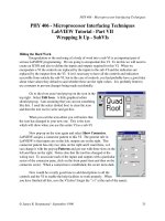
According to (Brussel et al, 1998) a fabrication system is composed of the following generic
entities and domains that are associated to the production:
Supply
Holon
Resource
Holon
Order
Holon
Product
Holon
Production information
Processinformation
Real -time order
execution
Process
domain
Production
domain
Business
domain
Adaptation from
Brussel and Nylund
Fig. 1. HMS structure (Brussel et al, 1998, Nylund, 2008), with supply/domain extension
Entities and domains have different purposes in the system, and are described in the
PROSA reference architecture which explains the structure of a fabrication system using
three basic holons: Product- (PH), Resource- (RH) and Order-Holon (OH) (Brussel et al,
1998). These entities are interconnected two by two with the process-, production- and
Holonic Robot Control for Job Shop Assembly by Dynamic Simulation
75
business domains (Nylund et al., 2008). The process- along with the production domains
characterizes the system from the internal point of view. The first, process domain, is related
with the system's capabilities to be able to execute certain operations that are needed to
manufacture products offered to the clients. These capabilities are defined by the products
and are realized by the resources. The second one, the production domain, manages the real-
time information which relates the orders to the resources. This information is subject to
offline and online scheduling in order to optimize the functioning of the fabrication system.
The last domain, the business domain, relates orders to products and the fabrication system to
the external world represented by clients.
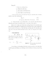
Generic structure of a holon
Fig. 2 shows the structure of a generic holon, containing the digital, real, virtual and
communication parts.
Fig. 2. The structure of a generic holon (Nylund et al., 2008)
In order for all of the different holons of the system to cooperate they must have similar
structures, especially similar information structure. According to (Nylund et al., 2008) a
general entity is composed of a real part which represents the physical resource capable of
performing operations on products, a virtual part which is the model of the entity, a digital
part in charge with the decision making and a communication port responsible for
cooperation with the surrounding environment.
2.2 Component entities
The distributed control solution proposed in this project provides a set of functionalities
rending the material-conditioning cell flexible, rapidly reacting to changes in client’s orders
(batch size, type of products, alternate technologies, rush orders, updated programs), and
fault-tolerant to resources getting down temporarily. In fact, the holonic control architecture
proposed follows the key features of the PROSA reference architecture (Van Brussel et al,
1998; Valkaenars et al, 1994), extended with:
• Automatic switching between hierarchical (for efficient use of resources and global
production optimization) and heterarchical (for agility to order changes, e.g. rush orders,
and fault tolerance to resource breakdowns) production control modes.
• Automatic planning and execution of assembly component supply; automatic
generation of self-supply tasks upon detecting local storage depletion,
Programmable Logic Controller
76
• In line vision-based parts qualifying and quality control of products in various
execution stages.
• Robotized material processing (e.g. assembling, fastening) under visual control /
guidance.
As suggested by the PROSA abstract, the manufacturing system was broken down into
three basic holons, the Resource Holon (RH), the Product Holon (PH), and the Order Holon
(OH). Each of these holons may exist more than once to fully define the manufacturing cell.
Order Holons are created by a Global Production Scheduler from the aggregate list of
product orders (APO) generated at ERP level.
Alternate OH are automatically created in response to changes in product batches (rush
orders) and to failures occurring during execution (resource breakdown, storage depletion).
A holon designs a class containing data fields as well as functionality. Beside the
information part, holons usually possess a physical part, like the product_on_pallet for OH
(Duffie and Prabhu, 1994).
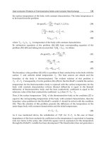
The way in which different types of holons communicate with each other and the type of
information they exchange depends on the nature of the manufacturing cell. Fig. 3 shows
the interaction diagram of the basic holon classes as they were implemented into software to
solve scheduling and failure/recovery management problems. A separate software module,
Fig. 3. Basic holon cooperation and communication structure in the semi-heterarchical
control architecture
Resource Holons
Product Holons
(operation, tool,
material, storage)
Order Holons
CNP
Customer
Orders
PLC Files
Current status
Available operating modes,
models, programs
Job scheduling
Job re-scheduling
Batch (OH set) execution,
Product traceability
Transfer for execution
(work-to-do)
Describe
wor
k
-to-plan
Announce
wor
k
-to-do
Robot controllers,
Machine CNC,
Conveyor devices
Announce
capacity
Provide
resource
schedule
Product
Resource
failure /
recovery
capacity
Storage
depletion
Expertise Holons
Order change
Due data, rush tag
Holonic Robot Control for Job Shop Assembly by Dynamic Simulation
77
the HolonManager hosts all holons in form of arrays of certain types of holons and
coordinates the data exchange among them.
The HolonManager entity is responsible with the planning (with help of Expertise Holons –
EH) and management of OH exactly as Staff Holons in the PROSA architecture do; in
addition, the HolonManager interfaces the application with the exterior (maps OH into
standard PLC file and tracks OH execution for user feedback). Since a single holon may be
seen as a class object in the object oriented programming environment (C# and .net 3.0
framework tools have been used), each of the three basic holon types was realized as a
separate class.
The instances necessary to define the manufacturing cell are then hosted by the class
Holons.HolonManager. Each type is present as an array which may be scaled dynamically if
necessary. Thus, the array of Holons.Product class instances assumes a size of existing
product types; each element represents one product type with all necessary info to generate
OH of this product type.
The resource holon (RH) holds information about manufacturing resources (robots
manipulators, grippers, machine tools, video cameras, magnetic sensors, RFID devices, a.o.).
In general any resource may have a number of sub-resources (e.g. a robot manipulator with
gripper with two fingers with force sensors), which are seen as holons. This project
considers an entire resource with all its sub-resources as a holon without making the
distinction of sub-systems. The hardware part of this type of holon is the actual physical
robot and gripper with its functions. A permanent data exchange between hardware and
software ensures that the actual status is accessible through the software representation of
the resource holon.
A product holon (PH) holds information about a product type. Any (assembly) type that
may be produced within the manufacturing system and resource setup must be defined in a
product holon. The fact that such a holon exists does not necessarily mean that the
respective product is being really assembled. Only the array of order holons (described in
the next paragraph) will specify that something is manufactured and in what quantity. The
product information is more of a theoretical description of the physical counter piece but not
directly associated with one individual physical item, unlike the resource holon. However,
the availability of assembling components is ultimately checked by the PLC prior to
authorize the final transfer of a pallet carrying the product to be assembled in a robot-vision
workstation (see Fig. 6).
An order holon represents all information necessary to produce one item
of a certain
product type. This holon is directly associated with the emerging item; it holds the
information about the status of this very item at any time reaching from assembly not started
yet throughout order progressing to order completed. Furthermore a complete manufacturing
schedule must be computed holding all necessary information relevant for the production
cell to successfully complete these orders, eventually satisfying a cost function such as the
throughput or resource loading.
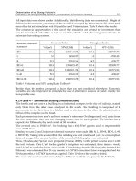
Before production starts for a specific aggregate order, customer commands exist in form of
electronic information. If a certain product needs to be manufactured n times, n identical raw
order holons are first created (Fig. 4).
During production execution orders can be seen as they progressively develop on a carrying
support (pallet) in the system; after one order has been completed, the item gets cleared
from the exiting pallet and has now a physical form. Before a schedule is defined for an
Programmable Logic Controller
78
aggregate order, raw order holons are created based on the information stored in the
product holon.
Fig. 4. Queue of two products (raw order holons) with a total of 7 items
A layer of Order Holons (
Pp
p
≤≤1 ,OH
) of variable depth, corresponding to assembly
plans computed off line for the
P
final products is the output of the production scheduler fed
with raw customer orders. A basic (quasi optimal) process plan is generated as a sequence of
Order Holons (assembled products). Production planning uses the Step Scheduler
developed both for production start up and resource failure and recovery situations. To
formalize the OH scheduling process, the notations and definitions below are introduced:
=O Set of all operations (assembly, conditioning)
=
P
Set of all assemblies (final products)
=
p
OA
Set of operations for assembly
PpA
p
∈,
=L Set of all resource types
=
l
Q Set of resources of type
Lll
∈
,
=
t
Current scheduling time
=
lq
r Resource q of type l , LlQq
l
∈
∈
,
For the networked assembly problem, the following types of resources were defined:
•
=
q
r
1
assembly robot manipulator, 2,1
=
q : SCARA, 4,3
=
q : vertical articulated;
•
=
q
r
2
gripper, 2,1
=
q : 2(3) –finger number, 4,3
=
q : flat / concave-contact profile;
•
=
q
r
3
end-effector tool, 3,2,1
=
q : none / bolt / screwdriver;
•
=
q
r
4
physical-virtual camera duality (
ji
VP ),
ii
nvjnvq ≤≤=
∑
1 , ,, 2,1 ,
where
=
i
nv no. of virtual cameras defined and installed for each physical camera
91 , ≤≤ ii
;
•
=
q
r
5
magnetic code R/W device,
4,3,2,1
=
q
.
Resource
lq
r
is: operational if it can be used after a finite time delay
lq
Δ
,
0,, ≥Δ∈∈
lql
LlQq
,
available if
0=Δ
lq
, and down otherwise. An assembly plan
)(
AP
δ
p
of a product
p
A
is
embedded in a resulting Order Holon OH as a vector of triplets, each specifying operation
number
i
o , processing time
)(δ
i
t of operation
i
o using assembly plan
δ
, and set of resources
)(δ
i
R to process the operation
i
o :
fiRto
iiip
≤≤=
δδ
δ
1 ), ],,,([ ,AP
)()(
)(
,
Holonic Robot Control for Job Shop Assembly by Dynamic Simulation
79
where
fiLlQqrrR
l
iqiq
i
≤≤∈∈=
δδδ
1 ,, },, ,{
)(
5
)(
1
)(
.
The Step Scheduler for assembly computes off-line the
Pp
p
≤≤
δ
1 ,OH
)(
at batch level
rending assembly plans
)(
AP
δ
p
available for products
PpA
p
∈,
. One operation Oo
i
∈ in
the
th
p
OH is executable if all resources needed to carry it out are defined as operational by at
least one
)(
AP
δ
p
. Operation Oo
i
∈
is schedulable at time
t
, if
1. No other operation (mounting, inspecting) upon the same product is being processed at
time
t
.
2. All operations preceding
i
o have been completed before time
t
.
3. All resources needed by the basic assembly plans
)(
AP
δ
p
to process operation
i
o are
available.
Since a single holon may be seen as a class object in the object oriented programming
environment (in this project the C# and .net 3.0 framework tools have been used), each of
the three basic holon types was realized as a separate class. The instances necessary to
define the manufacturing cell are then hosted by the Holons.HolonManager class.
The array of Holons.Product class instances assumes a size of currently present product
types; each element represents one product type with all necessary information to generate
orders of this product type. The last array composed of Holons.Order class instances has a
number of elements equal to the total count of items that needs to be manufactured. Each
element defines an order of a certain product type with its specific assembly schedule.
According to the definition (Koestler, 1967) a holon is an autonomous and collaborative
entity which contains a hardware and software part. In the case of the supply holon the
hardware part is represented by the pallet carrying pieces in the system and the software is
the application on the PLC which controls the path pallet and manages the exchange of
messages between the workplaces and the supplied station. The relationship between the
two sides is 1 to 1 and synchronization is done via the code written on the pallet (251-254).
Depending on when the supplies are sent there are two types of holons: one supplying the
workplaces at production start up, and the one re-supplying the workstations during
production execution. The life of a Supply Holon spreads during all the manufacturing
process. Unlike a normal order or a Supply Holon needed for initial feeding, where the
operations to be performed are established in advance, for a Supply Holon used at re-
feeding the operations are chosen dynamically depending on the usage of workstations.
During production a single Supply Holon stays in the system pending for re-feeding
operations. Another re-feeding constraint is the following: a pallet can carry only one type of
parts for re-supply because when a workstation signals that it has an empty stock it means
that it lacks a single type of piece. The type of piece is signaled to the PLC by a code similar
to code that is sent when an order requires the execution of an operation. This signal is then
sent to the workstation and is stored into a FIFO-type stack. From this stack re-feeding
requests will be taken.
A particular case of re-feeding is the initial supply, when all workstation stocks are empty.
In this case the number of Supply Holons will be extended to 4, which is the number of
Programmable Logic Controller
80
pallets which ensure that the system will not block. After re-feeding only the pallet that
supplies workstation during production remains in the system. The number of pallets is
computed based on the configuration of the transportation system (Fig. 5).
Fig. 5. Holonic manufacturing system with self-supply of assembly parts
Before production starts for a particular Aggregate List of Product Orders (APO created at
ERP level), the OHs exist only in electronic format; during production execution each OH
develops on a pallet in the system; after completion, the item gets cleared from the exiting
pallet and has now a physical form. OHs are created from raw orders (items in the APO list)
which are based on the information stored in the product holon. If a certain product needs
to be manufactured n times, then n identical raw orders are created first; when OH for these
Holonic Robot Control for Job Shop Assembly by Dynamic Simulation
81
raw orders are created, the information is distinct for each OH in terms of robot stations
which need to be visited and the time at which they are visited (Onori et al., 2006).
Unlike the product holon, seen as a general static entity describing a certain product type,
the order holon is the actual realization of one item of a product type and undergoes many
changes (of information as well as of physical nature) during manufacturing. An OH is
represented by a pallet carrier with a unique identifier on it (magnetic tag), the manufactured
product (on the pallet), and a management program running on the PLC communicating with
resource controllers.
The mappings between the (holonic) system requirements and the functional architecture
are included in Figs. 1 and 4. Fig. 6 describes the mappings between the functional
architecture and the physical one (for a particular implementation). The real world
representation refers to the model (the software counterpart of the RH, PH and OH set) of
the real production system which exists at the planning level.
Fig. 6. Mapping between the (holonic) system and the physical architecture
Programmable Logic Controller
82
3. Implementation methodology using holonic principles
The general information flow that characterizes the production system at enterprise level is
described in Fig. 7:
Customer
Order
Aggregate list
of
p
roduct
On line
Product
Off line
Product
Production Database &
Rules/Strategies, RH, PH
U
p
date
Supplier
Data
,
Job-Shop PLC Control
(OH/SH Execution,
RH Status Monitoring
)
SH
,
Reschedule Request at
Resource
Job-Shop Scheduler
(Batch Production
RH Status
Monitoring
(Robots, Cameras,
Holonic Bidding Mechanism
(Create SH for depleted storage
and alternate OH for WIP)
Supply- and WIP
R
eschedule
Insert new SH
& alternate
Cell
Cell
Station
Com
p
ute
Resource
Controllers
(
RC
,
CAPP
(
OH/SH
CAM, CAQC
(
OH/SH
CAD, CAE
(Customer
Orde
r
Marketing,
Sales (Offer
Re
q
uest
E
Fig. 7. Information and data flow of HMES with knowledge-based Service Oriented
Architecture for customer request management
After the definition of the process and production domains the fabrication cell is ready for
utilization and the business process can begin. In order for this process to be made flexible it
is proposed that the information on offer requests, offers to clients, order collection and
production feedback is retrieved through a web interface which is interconnected with the
process as described in Fig. 8 below:
Holonic Robot Control for Job Shop Assembly by Dynamic Simulation
83
GUI Scheduler /ProductionManager
Post available products
Cell PLC
Request batch production
Accept/Reject production
Feedback informations
Accept/Reject production
Resources
Request status
Send response
Request available operations
Send available operations
Compute schedule
Send schedule
Monitoring resources status
Question
Response
Write execution log
Define products based
on available operations
Start/Stop(with Reset)/
Renew production
Fig. 8. Time diagram representing messages exchanged between entities from the business
domain
Synchronization between the client interface and the planning and management application
for the work cell is done via the exchange of text files. There will be three types of files:
a. Input files for the scheduler
1. input_nr_orders.txt
For a command the client will provide the manufacturer with the following details: product
types, quantities and priorities. There are four levels of priority (0, 1, 2 and 3) where 3
represent the orders with the highest priority. Once this information is provided a
connection between them and production domain must be created in order to report its state
to the client. Therefore, besides the three fields that define a client order another field that
will make contact with customer orders is added. This is the customer index.
In this way, the file has the following structure:
nr_products$priority$product_name $index_client
Here, nr_orders (from the file input_nr_orders.txt) is an integer which increases at each
command. At each cycle of planning and production the application will retrieve the
information from the file with the lowest index and then will delete the file.
2. command.txt
It is better that once the orders are introduced in production it exists a way to intervene in
their execution. The reason is that for an undetermined cause the cancellation of orders'
execution should be possible. Therefore, through this file that contains a single row (the