Ar 1600m kato lắp đặt
Bạn đang xem bản rút gọn của tài liệu. Xem và tải ngay bản đầy đủ của tài liệu tại đây (4.21 MB, 124 trang )
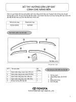
ALL TERRAIN CRANE
AR
AR-1600M
JAPANESE SPECIFICATIONS
CARRIER MODEL
SPEC. NO.
FAUN RTF160-5
AR-1600M-1-90101
The "fully automatic luffing jib" and the "luffing jib"
are optional equipment.
Refer to the specifications in the following pages
regarding the details of these optional jibs.
Control No. AR-1600M-1/MB-03
− 135 −
Return to index
AR-1600M-1 / MB-03
AR-1600M
CRANE SPECIFICATIONS
CRANE CAPACITY
13.5m Boom
18.1m Boom
22.6m Boom
31.8m Boom
40.9m Boom
45.4m Boom
50.0m Boom
Single top
<Reference>
Fully automatic
10.2m Jib
17.9m Jib
25.7m Jib
Luffing jib
11m Jib
20m Jib
29m Jib
37m Jib
45m Jib
160,000kg
110,000kg
100,000kg
65,000kg
50,000kg
42,000kg
30,000kg
9,400kg
luffing jib
18,600kg
9,300kg
5,600kg
75,000kg
47,000kg
27,000kg
8,500kg
5,800kg
BOOM ELEVATION
at
at
at
at
at
at
at
3.2m
5.0m
5.0m
7.0m
8.0m
9.0m
12.0m
(20part-line)
(13part-line)
(12part-line)
( 7part-line)
( 6part-line)
( 5part-line)
( 4part-line)
( 1part-line)
2 double-acting hydraulic cylinders
SWING
Hydraulic motor driven planetary gear reducer
Swing bearing
Disk type negative brake
2-speed (high/low) selection type
Pneumatically operated swing lock
OUTRIGGERS
Fully hydraulic H-type 3 steps
Slides and jacks each provided with independent
operation device.
Fully extended width
8.8m
Middle extended width
8.0m, 6.8m, 5.6m
Extended width detector provided.
Slide lock power pin provided.
at 10.0m ( 2part-line)
at 14.0m ( 1part-line)
at 16.0m ( 1part-line)
at
at
at
at
at
7.0m
10.0m
14.0m
40.0m
24.0m
(
(
(
(
(
8part-line)
6part-line)
4part-line)
1part-line)
1part-line)
REAR JACK
Hydraulic type (with grounding detector)
Individual operation type
COUNTERWEIGHT
MAX.LIFTING HEIGHT
Boom
50.0m
<Reference> Fully automatic luffing jib
<Reference> Luffing jib
50t, 44t, 34t, 25t
ENGINE FOR CRANE
78.0m
95.0m
Engine exclusive to upper component operation
Model MITSUBISHI 6D24-T
Type
4-cycle, 6 in-line cylinder, direct-injection,
water-cooled diesel engine
Piston displacement 11,945cc with turbo charger
Max. output 188kW (225PS) at 1,800min-1(rpm)
Max. torque 1,030N .m (105kg.m) at 1,400min-1(rpm)
MAX.WORKING RADIUS
Boom
47.0m
<Reference> Fully automatic luffing jib
<Reference> Luffing jib
55.0m
70.0m
BOOM LENGTH
13.5m - 50.0m
FUEL TANK CAPACITY
BOOM EXTENSION SPEED
280 liters
36.5m/ 210s
HYDRAULIC PUMPS
MAIN WINCH SINGLE LINE WINDING SPEED
130m/min
2 variable piston pumps and 2 gear pumps
(5th layer)
HYDRAULIC OIL TANK CAPACITY
AUXILIARY WINCH SINGLE LINE WINDING
SPEED
130m/min
Upper
Lower
(5th layer)
SAFETY DEVICES
BOOM ELEVATION ANGLE
Automatic moment limiter (AML)
Multiple display
With working range limiting function
Outrigger extension automatic detector (individual detection)
Weight combination automatic detector
Swing range controller
Swing automatic stop device
Boom elevation slow down and stop device
Over-winding cutout device
Dead winding holding device
Cable follower
Hook safety latch
Winch drum lock
Hydraulic safety valve
Hydraulic lock (elevation, telescoping, hoist, jack, jib tilt,
dismount)
Swing lock
Boom angle indicator
Level gauge
-1.5°- 83°
BOOM ELEVATION SPEED
-1.5°- 83°/80s
SWING ANGLE
360°continue
SWING SPEED
1.4/1.0rpm
WIRE ROPE
Main Winch
24mm x 340m (Diameter x Length)
Anti-rotate wire rope
Auxiliary Winch
24mm x 310m (Diameter x Length)
Anti-rotate wire rope
HOOK
160t
hook
110t
65t
25t
9.4t
hook
hook
hook
hook
1,585 liters
210 liters
(20part-line)
(Using additional sling and single top)
(13part-line)(Using single top)
( 7part-line)
( 3part-line)
( 1part-line)
EQUIPMENT
BOOM
5-section hydraulically telescoping boom of box
construction
(stage 2: sequential; stages 3,4,5: synchronized)
2-stage lock or no lock (spring type and air cylinder type)
BOOM EXTENSION
4 double-acting hydraulic cylinders
SINGLE TOP
Single sheave. Mounted to main boom head by pin.
HOIST
Driven by hydraulic variable motor and via planetary gear
reducer.
Automatic brake
2-speed (high/low) selection type
2 single winches
Oil cooler
Boom dismount device
Swing frame dismount device
Counterweight dismount device
Boom elevation creeping mode setting device
AML external warning lamp
Hook movement amount indicator
Wind velocity meter
Iron plate
Hot and cool boxes
Lunch table
Air conditioner
Drum monitor
FM radio
Back monitor
OPTIONAL EQUIPMENT
Swing alarm
− 136 −
AR-1600M-1 / MB-03
CARRIER SPECIFICATIONS
GENERAL DATA
MANUFACTURER
DIMENSIONS (CARRIER ONLY)
FAUN GmbH
Overall length
Overall width
Overall height
Wheel base
CARRIER MODEL
RTF 160-5
ENGINE
Model
Type
OM442LA (Benz)
4-cycle, V8-cylinder, direct-injection,
turbo diesel engine with inter cooler
Piston displacement 14,618cc
Max. output
503PS at 2,100rpm
Max. torque
206kg.m at 1,100 to 1,600rpm
Tread
13,640mm
3,000mm
2,775mm
2,850mm + 1,700mm + 2,550mm +
1,700mm
2,557mm
WEIGHTS (CARRIER ONLY)
Gross vehicle weight
Total
Front: 1st + 2nd axle
Rear: 3rd axle
4th + 5th axle
TRANSMISSION
Fully automatic
5-forward and 1-reverse speeds
Sub-transmission provided.
40,900kg (Two-man type)
19,500kg
1,400kg
20,000kg
PERFORMANCE (CARRIER ONLY)
Max. traveling speed
Gradeability (tan θ)
Min. turning radius
8-wheel steering
10-wheel steering
CLUTCH
Torque converter provided.
Automatic lock-up mechanism provided.
DRIVING METHOD
60km/h
0.73
11.8m
9.7m
Note:
1 The swing jib of this crane must be removed and
transported separately from the carrier when running
on public roads.
2 This crane is covered by Class C Conditions under
the Basic Running Conditions of the Road Traffic Act.
10 x 6
10 x 8 --- Off load (with def-lock mechanism)
AXLE (all axles)
Full-floating type
SUSPENSION (all axles)
Hydraulic pneumatic suspension
Stroke: +149mm/ -113mm
STEERING
Type: Left-side handle
Fully hydraulic power steering
2 circuits
Emergency power steering
Mode: Normal (6 front wheels, 2 rear wheels)
Clamp (10 wheels)
Crab (10 wheels)
Rear steering (4 rear wheels)
BRAKE SYSTEM
Service Brake
Air brake on all wheels
2 circuits
Parking Brake
4th and 5th axles (4-wheel) spring brake for public
thoroughfare traveling
(3rd, 4th and 5th axles (6-wheel) spring brake for
on-site traveling)
Emergency Brake
Works by applying the parking brake
Auxiliary Brake
Flow type retarder (transmission built-in)
Exhaust brake
ELECTRIC SYSTEM
24 V DC. 2 batteries of 12V-170Ah
FUEL TANK CAPACITY
700 liters
CAB
Two-man type
TIRES
16.00R25 (all wheels)
WHEEL
11.25-25 (all wheels)
STANDARD EQUIPMENT
Air conditioner
FM radio
Mud guard
Centralized lubrication unit
Bed for napping
− 137 −
AR-1600M-1 / MB-03
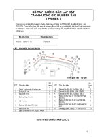
BOOM TOTAL RATED LOADS
1. The total rated loads shown are for the case where the outriggers are set horizontally on firm level ground. The
values above the bold lines are based on the crane strength while those below are based on the crane stability.
2. The weights of the slings and hooks (160t hook with attachment: 2,700kg, 110t hook: 2,100kg, 65t hook: 940kg, 25t
hook: 730kg, 9.4t hook: 430kg) are included in the total rated loads shown.
3. The total rated load is based on the actual working radius including the deflection of the boom.
4. The table below shows the classification of Performances A to I of the total rated load.
Counterweight
50t
44t
8.8m
A (C)
8.0m
A (C)
6.8m
5.6m
2.7m
Outrigger extension width
34t
25t
0t
A (D)
C (E)
D (F)
G (H)
B (D)
D (E)
E (F)
G (H)
C (C)
D (D)
E (E)
F (F)
H (H)
-
-
F (F)
G (G)
H (H)
-
-
-
-
I (I)
- If the rear jack is not used, the performance
classification in parentheses shall apply.
At this time, the maximum total rated load is 50t.
- Performance I shall apply only to the 13.5m
boom, and the working area is as shown in the
illustration.
5. The chart below shows the standard number of part lines for each boom length. The load per line should not exceed
92.1kN (9.4t) for both the main winch and the auxiliary winch.
A
13.5m
18.1m
22.6m
31.8m
40.9m
45.4m
50.0m
Single top
H
(20)12
(13)12
12
7
6
5
4
1
A= Boom length H= No. of part-lines
For 20 part lines in parentheses, the attachment and single top should be used, and for 13 part lines, the single top
should be used.
6. The total rated loads shown are for the case where the 2nd boom section fixing pin is used.
When the 2nd boom section fixing pin is not used, the maximum total rated loads relative to the boom length are
restricted as shown in the table below.
Boom length
Max. total rated load (t)
Over 13.5m
Over 18.1m
up to 18.1m
up to 50.0m
58
26
7. The total rated load for the single top shall be the value obtained by subtracting the weight of the hook mounted to
the boom from the total rated load of the boom and must not exceed 9.4t.
8. When the maximum instantaneous velocity is 10m/s or more, stop crane operation.
9. Markθin the total rated load chart shows the boom angle range (under no load).
− 138 −
AR-1600M-1 / MB-03
Unit : ton
Performance A
A
13.5m
18.1m
22.6m
3.2m
160.0
110.0
100.0
3.5m
151.7
110.0
100.0
4.0m
139.6
110.0
100.0
4.5m
129.3
110.0
100.0
5.0m
118.8
110.0
100.0
6.0m
100.6
97.0
90.0
65.0
7.0m
86.9
86.1
81.4
65.0
50.0
8.0m
76.2
76.5
71.8
59.6
50.0
42.0
9.0m
67.6
67.4
65.9
54.5
47.3
42.0
30.0
10.0m
62.0
60.2
58.8
50.4
44.5
38.8
30.0
11.0m
51.4
54.2
52.8
46.9
41.8
36.6
30.0
12.0m
49.4
47.3
43.3
38.5
34.5
30.0
14.0m
40.7
38.7
37.2
32.6
30.2
26.4
16.0m
23.9
32.3
31.6
28.5
26.5
23.3
18.0m
27.8
27.6
25.0
23.1
20.7
20.0m
20.2
24.1
21.8
20.7
18.4
22.0m
20.2
19.1
18.2
16.6
24.0m
17.1
17.0
16.4
14.8
26.0m
14.6
15.1
14.7
13.3
28.0m
12.6
13.2
13.1
12.0
30.0m
11.4
11.6
10.8
32.0m
9.9
10.2
9.6
34.0m
8.8
8.9
8.6
36.0m
7.7
7.8
7.6
38.0m
6.5
6.7
6.7
40.0m
5.9
6.0
42.0m
5.1
5.2
B
31.8m
40.9m
45.4m
50.0m
44.0m
4.5
46.0m
3.9
3.6
47.0m
θ (°)
0∼83
0∼83
0∼83
10∼83
A= Boom length B= Working radius
θ= Boom angle range (for the unladen condition)
− 139 −
11∼83
12∼83
12∼83
AR-1600M-1 / MB-03
Unit : ton
Performance B
A
13.5m
18.1m
22.6m
3.2m
160.0
110.0
100.0
3.5m
151.7
110.0
100.0
4.0m
139.6
110.0
100.0
4.5m
129.3
110.0
100.0
5.0m
118.8
110.0
100.0
6.0m
100.6
97.0
90.0
65.0
7.0m
86.9
86.1
81.4
65.0
50.0
8.0m
76.2
76.5
71.8
59.6
50.0
42.0
9.0m
67.6
67.4
65.9
54.5
47.3
42.0
30.0
10.0m
62.0
60.2
58.8
50.4
44.5
38.8
30.0
11.0m
51.4
54.2
52.8
46.9
41.8
36.6
30.0
12.0m
49.4
47.3
43.3
38.5
34.5
30.0
14.0m
40.7
38.7
37.2
32.6
30.2
26.4
16.0m
23.9
32.3
31.6
28.5
26.5
23.3
18.0m
26.1
27.6
25.0
23.1
20.7
20.0m
20.2
23.3
21.8
20.7
18.4
22.0m
19.5
19.1
18.2
16.6
24.0m
16.5
17.0
16.4
14.8
26.0m
14.1
14.9
14.7
13.3
28.0m
12.0
12.8
13.1
12.0
30.0m
11.1
11.4
10.8
32.0m
9.4
9.8
9.6
34.0m
8.0
8.3
8.6
36.0m
6.8
7.1
7.4
38.0m
5.7
6.0
6.2
40.0m
5.0
5.2
42.0m
4.2
4.4
B
31.8m
40.9m
45.4m
50.0m
44.0m
3.6
46.0m
2.9
2.6
47.0m
θ (°)
0∼83
0∼83
0∼83
10∼83
A= Boom length B= Working radius
θ= Boom angle range (for the unladen condition)
− 140 −
11∼83
13∼83
13∼83
AR-1600M-1 / MB-03
Unit : ton
Performance C
A
13.5m
18.1m
22.6m
3.2m
160.0
110.0
100.0
3.5m
151.7
110.0
100.0
4.0m
139.6
110.0
100.0
4.5m
129.3
110.0
100.0
5.0m
118.8
110.0
100.0
6.0m
100.6
97.0
90.0
65.0
7.0m
86.9
85.8
81.4
65.0
50.0
8.0m
74.6
73.5
71.8
59.6
50.0
42.0
9.0m
65.1
64.0
63.2
54.5
47.3
42.0
30.0
10.0m
57.6
56.4
55.6
50.4
44.5
38.8
30.0
11.0m
51.4
50.2
49.3
46.9
41.8
36.6
30.0
12.0m
45.0
44.1
43.3
38.5
34.5
30.0
14.0m
36.8
36.0
37.2
32.6
30.2
26.4
16.0m
23.9
27.8
30.1
28.5
26.5
23.3
18.0m
22.0
24.1
25.0
23.1
20.7
20.0m
17.8
19.7
20.6
20.7
18.4
22.0m
16.3
17.2
17.5
16.6
24.0m
13.5
14.4
14.8
14.8
26.0m
11.3
12.2
12.5
12.8
28.0m
9.5
10.3
10.6
10.9
30.0m
8.7
9.1
9.3
32.0m
7.4
7.7
8.0
34.0m
6.3
6.5
6.8
36.0m
5.3
5.5
5.8
38.0m
4.5
4.7
4.9
40.0m
3.9
4.1
42.0m
3.3
3.4
B
31.8m
40.9m
45.4m
50.0m
44.0m
2.8
46.0m
2.1
1.8
47.0m
θ (°)
0∼83
0∼83
0∼83
10∼83
A= Boom length B= Working radius
θ= Boom angle range (for the unladen condition)
− 141 −
11∼83
13∼83
13∼83
AR-1600M-1 / MB-03
Unit : ton
Performance D
A
13.5m
18.1m
22.6m
3.2m
160.0
110.0
100.0
3.5m
150.0
110.0
100.0
4.0m
134.3
110.0
100.0
4.5m
121.4
110.0
100.0
5.0m
110.6
109.7
100.0
6.0m
93.6
92.7
90.0
65.0
7.0m
80.7
79.8
79.1
65.0
50.0
8.0m
70.7
69.7
68.9
59.6
50.0
42.0
9.0m
61.8
60.6
59.8
54.5
47.3
42.0
30.0
10.0m
54.5
53.4
52.5
50.4
44.5
38.8
30.0
11.0m
47.7
46.1
45.0
46.9
41.8
36.6
30.0
12.0m
39.8
38.7
41.0
38.5
34.5
30.0
14.0m
30.6
29.6
31.7
32.6
30.2
26.4
16.0m
23.9
22.7
24.9
26.0
26.4
23.3
18.0m
17.6
19.7
20.7
21.1
20.7
20.0m
13.9
15.9
16.8
17.2
17.5
22.0m
12.9
13.8
14.1
14.5
24.0m
10.5
11.4
11.7
12.0
26.0m
8.6
9.4
9.7
10.0
28.0m
7.0
7.8
8.1
8.4
30.0m
6.4
6.7
7.0
32.0m
5.2
5.5
5.8
34.0m
4.2
4.5
4.8
36.0m
3.4
3.6
3.9
38.0m
2.7
2.9
3.1
2.2
2.4
B
31.8m
40.9m
40.0m
θ (°)
0∼83
0∼83
0∼83
10∼83
A= Boom length B= Working radius
θ= Boom angle range (for the unladen condition)
− 142 −
12∼83
45.4m
19∼83
50.0m
34∼83
AR-1600M-1 / MB-03
Unit : ton
Performance E
A
13.5m
18.1m
22.6m
3.2m
160.0
110.0
100.0
3.5m
150.0
110.0
100.0
4.0m
134.3
110.0
100.0
4.5m
121.4
110.0
100.0
5.0m
110.6
109.7
100.0
6.0m
93.6
92.7
90.0
65.0
7.0m
80.7
79.8
79.1
65.0
50.0
8.0m
70.7
69.7
68.9
59.6
50.0
42.0
9.0m
60.4
58.7
57.6
54.5
47.3
42.0
30.0
10.0m
50.5
48.9
47.8
50.2
44.5
38.8
30.0
11.0m
43.1
41.5
40.4
42.8
41.8
36.6
30.0
12.0m
35.7
34.7
36.9
37.9
34.5
30.0
14.0m
27.3
26.2
28.3
29.3
29.7
26.4
16.0m
21.5
20.4
22.4
23.3
23.7
23.3
18.0m
16.1
18.0
18.9
19.2
19.6
20.0m
12.8
14.6
15.5
15.8
16.2
22.0m
12.0
12.8
13.2
13.5
24.0m
9.6
10.7
11.0
11.3
26.0m
7.7
8.7
9.1
9.4
28.0m
6.0
7.0
7.4
7.7
30.0m
5.5
5.9
6.2
32.0m
4.3
4.7
5.0
34.0m
3.3
3.6
3.9
36.0m
2.4
2.7
3.0
1.8
2.1
B
31.8m
40.9m
38.0m
θ (°)
0∼83
0∼83
0∼83
10∼83
A= Boom length B= Working radius
θ= Boom angle range (for the unladen condition)
− 143 −
18∼83
45.4m
25∼83
50.0m
34∼83
AR-1600M-1 / MB-03
Unit : ton
Performance F
A
13.5m
18.1m
22.6m
3.2m
160.0
110.0
100.0
3.5m
150.0
110.0
100.0
4.0m
134.3
110.0
100.0
4.5m
121.4
110.0
100.0
5.0m
110.6
109.7
100.0
6.0m
93.6
92.7
90.0
65.0
7.0m
80.3
78.5
77.1
65.0
50.0
8.0m
62.8
61.1
59.8
59.6
50.0
42.0
9.0m
50.9
49.3
48.1
50.7
47.3
42.0
30.0
10.0m
42.4
40.8
39.7
42.1
43.2
38.8
30.0
11.0m
36.0
34.4
33.3
35.6
36.6
36.6
30.0
12.0m
29.4
28.3
30.5
31.5
32.0
30.0
14.0m
22.0
21.0
23.1
24.1
24.5
24.8
16.0m
17.0
16.0
18.0
18.9
19.2
19.6
18.0m
12.1
14.2
15.0
15.4
15.7
20.0m
9.0
11.2
12.1
12.5
12.8
22.0m
8.7
9.7
10.1
10.4
24.0m
6.6
7.6
8.0
8.4
26.0m
4.8
5.8
6.2
6.6
28.0m
3.4
4.4
4.8
5.1
30.0m
3.1
3.5
3.8
32.0m
2.1
2.4
2.8
B
θ (°)
0∼83
0∼83
0∼83
31.8m
9∼83
A= Boom length B= Working radius
θ= Boom angle range (for the unladen condition)
− 144 −
40.9m
30∼83
45.4m
38∼83
50.0m
44∼83
AR-1600M-1 / MB-03
Unit : ton
Performance G
A
13.5m
18.1m
22.6m
3.2m
148.0
110.0
100.0
3.5m
137.8
110.0
100.0
4.0m
123.3
110.0
100.0
4.5m
111.4
110.0
100.0
5.0m
101.4
100.5
99.9
6.0m
85.2
84.1
83.2
65.0
7.0m
68.4
66.6
65.2
65.0
50.0
8.0m
53.1
51.5
50.2
53.0
50.0
42.0
9.0m
42.8
41.2
40.1
42.6
43.7
41.1
30.0
10.0m
34.6
32.7
31.4
34.3
35.7
36.2
30.0
11.0m
28.2
26.3
25.1
27.9
29.1
29.6
30.0
12.0m
21.6
20.4
23.0
24.2
24.7
25.1
14.0m
14.9
13.8
16.2
17.3
17.7
18.1
16.0m
10.6
9.2
11.7
12.7
13.1
13.5
18.0m
5.6
8.3
9.4
9.8
10.2
20.0m
3.1
5.5
6.7
7.2
7.6
3.4
4.5
5.0
5.4
B
31.8m
22.0m
θ (°)
0∼83
0∼83
4∼83
36∼83
A= Boom length B= Working radius
θ= Boom angle range (for the unladen condition)
− 145 −
40.9m
52∼83
45.4m
58∼83
50.0m
61∼83
AR-1600M-1 / MB-03
Unit : ton
Performance H
A
13.5m
18.1m
22.6m
3.2m
148.0
110.0
100.0
3.5m
137.8
110.0
100.0
4.0m
123.3
110.0
100.0
4.5m
110.0
107.2
100.0
5.0m
82.4
80.0
78.1
6.0m
53.2
51.2
49.7
53.2
7.0m
37.9
36.1
34.8
37.8
39.2
8.0m
28.5
26.8
25.6
28.4
29.7
30.2
9.0m
22.2
20.6
19.4
22.0
23.2
23.7
24.1
10.0m
17.6
16.1
15.0
17.4
18.5
19.0
19.4
11.0m
14.2
12.6
11.6
14.0
15.0
15.5
15.8
12.0m
10.0
8.7
11.2
12.3
12.7
13.1
14.0m
5.6
7.0
8.2
8.6
9.0
B
θ (°)
0∼83
0∼83
47∼83
31.8m
58∼83
Unit : ton
Performance I
A
B
13.5m
3.2m
7.0
3.5m
7.0
4.0m
7.0
4.5m
7.0
5.0m
7.0
6.0m
7.0
7.0m
7.0
8.0m
7.0
9.0m
7.0
10.0m
7.0
11.0m
7.0
(°)
6∼83
θ
A= Boom length B= Working radius
θ= Boom angle range (for the unladen condition)
− 146 −
40.9m
67∼83
45.4m
70∼83
50.0m
72∼83
AR-1600M-1 / MB-03
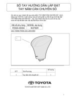
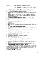
WORKING RADIUS - LIFTING HEIGHT
[BOOM]
BOOM
BOOM
LIFTING HEIGHT (m)
BOOM
BOOM
BOOM
BOOM
BOOM
WORKING RADIUS (m)
NOTES:
1. The deflection of the boom is not incorporated in the figure above. The above figure is for Performance A.
2. The boom extension for each boom are as follows:
50.0m BOOM
45.4m BOOM
40.9m BOOM
31.8m BOOM
22.6m BOOM
18.1m BOOM
13.5m BOOM
− 147 −
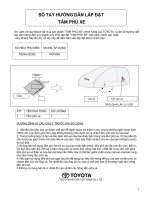
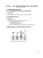
[On public thoroughfare traveling condition]
DIMENSIONS (1/100)
AR-1600M-1 / MB-03
− 148 −
[On-site traveling condition]
DIMENSIONS (1/100)
AR-1600M-1 / MB-03
− 149 −
◆ MEMO ◆
− 150 −
AR-1600M-1 / FLJ-02
ALL TERRAIN CRANE
AR
AR-1600M
(Fully Automatic Luffiing Jib)
JAPANESE SPECIFICATIONS
These specifications are for the optional fully
automatic luffing jib for the AR-1600M type crane.
Refer to these specifications along with
specification control no. AR-1600M-1/MB.
Control No. AR-1600M-1/FLJ-02
− 151 −
Return to index
AR-1600M-1 / FLJ -02
AR-1600M
CRANE SPECIFICATIONS
CRANE CAPACITY
10.2m
17.9m
25.7m
Jib
Jib
Jib
18,600kg
9,300kg
5,600kg
at 10.0m
at 14.0m
at 16.0m
(2part-line)
(1part-line)
(1part-line)
JIB
3-section synchronously telescoping boom of box
construction
Hydraulic non-stage offset (5°- 60°) type
1.7m (fixing part) + 10.2m - 25.7m (elevating/telescoping
part)
JIB
1 double-acting hydraulic cylinder
1 wire rope type telescoping device
JIB LENGTH
10.2m
17.9m
25.7m
MAX.LIFTING HEIGHT
78.0m
MAX.WORKING RADIUS
55.0m
− 152 −
AR-1600M-1 / FLJ-02
BOOM TOTAL RATED LOADS
1. The total rated loads shown are for the case where the outriggers are set horizontally on firm level ground. The
values above the bold lines are based on the crane strength while those below are based on the crane stability.
2. The weights of the slings and hooks (25t hook: 730kg, 9.4t hook: 430kg) are included in the total rated loads shown.
3. The total rated load is based on the actual working radius including the deflection of the boom.
4. The table below shows the classification of Performances FA to FF of the total rated load.
Counterweight
Outrigger extension width
50t
44t
34t
25t
0t
8.8m
FA (FC) FA (FD) FC (FE) FD (FF)
FF (-)
8.0m
FA (FC) FB (FD) FD (FE) FE (FF)
-
6.8m
FC (FC) FD (FD) FE (FE) FF (FF)
-
FF (FF) FF (FF)
-
5.6m
-
-
2.7m
-
-
-
-
-
- If the rear jack is not used, the performance classification in parentheses shall apply.
5. The standard hook and number of part lines are shown in the total rated loads chart. The load per line should not
exceed 9.4t.
6. When the maximum instantaneous velocity is 10m/s or more, stop crane operation.
7. Markθin the total rated load chart shows the boom angle range (under no load).
8. The total rated loads shown are for the case where the 2nd boom section fixing pin is used.
Ensure that the 2nd boom section fixing pin is used with the fully automatic luffing jib.
− 153 −
AR-1600M-1 / FLJ -02
Performance FA
31.8m boom + 1.7m + Fully automatic luffing jib
Unit : ton
C
1.7m + 10.2m
D
5°
15°
B (m)
E
M
7.0
81.0
18.6
8.0
79.7
18.6
9.0
78.4
10.0
77.1
11.0
25°
E
M
18.6
80.8
13.9
17.6
79.5
75.8
16.8
78.2
12.0
74.5
16.0
14.0
71.8
16.0
40°
M
13.4
81.5
10.8
12.9
80.1
10.5
76.8
12.4
78.8
10.2
81.3
8.2
14.7
74.1
11.6
76.1
9.7
78.4
7.9
80.6
6.7
69.0
13.6
71.4
10.9
73.3
9.2
75.6
7.7
77.5
6.6
18.0
66.1
12.6
68.6
10.3
70.4
8.8
72.6
7.4
74.4
6.6
20.0
63.2
11.8
65.7
9.8
67.5
8.5
69.6
7.3
71.1
6.6
22.0
60.2
11.0
62.6
9.3
64.5
8.2
66.5
7.1
67.7
6.6
24.0
57.0
10.4
59.5
8.9
61.3
7.9
63.2
7.0
26.0
53.8
9.8
56.3
8.6
58.0
7.7
59.8
7.0
28.0
50.3
9.3
52.8
8.2
54.5
7.5
56.1
6.9
30.0
46.6
8.8
49.2
8.0
50.8
7.1
52.2
6.9
32.0
42.6
7.9
45.2
7.7
46.7
6.8
34.0
38.2
6.7
40.7
6.7
42.2
6.4
36.0
33.1
5.5
35.6
5.7
36.9
5.8
38.0
27.2
4.4
29.4
4.5
40.0
19.1
θ (°)
2.7
18 ∼ 83
28 ∼ 83
35 ∼ 83
F
E
M
60°
E
51 ∼ 83
E
M
66 ∼ 83
25t hook (730kg)
2part-line
H
Unit : ton
C
1.7m + 17.9m
D
B (m)
5°
E
15°
M
E
25°
M
E
40°
M
E
M
60°
E
M
10.0
80.5
9.3
11.0
79.5
9.3
12.0
78.4
9.3
14.0
76.3
8.9
79.5
7.2
16.0
74.1
8.5
77.3
6.6
80.3
5.4
18.0
71.8
7.8
75.0
6.2
78.0
5.0
20.0
69.5
7.2
72.7
5.7
75.6
4.8
79.2
3.8
22.0
67.1
6.7
70.3
5.5
73.3
4.6
76.7
3.8
80.2
3.1
24.0
64.7
6.2
67.9
5.2
70.8
4.4
74.1
3.6
77.4
3.1
26.0
62.2
5.8
65.4
4.9
68.3
4.2
71.5
3.5
74.5
3.0
28.0
59.6
5.4
62.8
4.6
65.7
4.0
68.7
3.3
71.4
3.0
30.0
56.9
5.1
60.1
4.4
63.0
3.9
65.9
3.3
68.2
3.0
32.0
54.1
4.8
57.4
4.2
60.2
3.8
62.9
3.3
34.0
51.2
4.5
54.5
4.0
57.2
3.6
59.8
3.2
36.0
48.2
4.3
51.4
3.9
54.1
3.5
56.4
3.2
38.0
44.9
4.1
48.1
3.8
50.8
3.5
52.8
3.2
40.0
41.3
3.9
44.6
3.8
47.3
3.5
42.0
37.5
3.7
40.7
3.7
43.3
3.5
44.0
33.0
3.5
36.3
3.6
38.7
3.5
46.0
27.7
3.1
30.9
3.3
48.0
20.3
θ (°)
F
H
1.8
19 ∼ 83
29 ∼ 83
37 ∼ 83
51 ∼ 83
9.4t hook (430kg)
1part-line
C= Jib length D= Jib offset B= Working radius (m)
E= Boom angle M= Total rated load F= Standard hook
− 154 −
H= No. of part-line
67 ∼ 83