Báo cáo hóa học: " Research Article Maximum SINR Synchronization Strategies in Multiuser Filter Bank Schemes" potx
Bạn đang xem bản rút gọn của tài liệu. Xem và tải ngay bản đầy đủ của tài liệu tại đây (850.4 KB, 11 trang )
Hindawi Publishing Corporation
EURASIP Journal on Wireless Communications and Networking
Volume 2010, Article ID 745128, 11 pages
doi:10.1155/2010/745128
Research Article
Maximum SINR Synchronization Strategies in Multiuser
Filter Bank Schemes
Francesco Pecile and Andrea M. Tonello (EURASIP Member)
Dipartimento di Ingegneria Elettrica Gestionale e Meccanica (DIEGM), Universit
`
adiUdine,
Via delle Scienze 208
−33100 Udine, Italy
Correspondence should be addressed to Andrea M. Tonello,
Received 23 November 2009; Revised 11 June 2010; Accepted 21 July 2010
Academic Editor: Carles Anton-Haro
Copyright © 2010 F. Pecile and A. M. Tonello. This is an op en access article distributed under the Creative Commons Attribution
License, which permits unrestricted use, distribution, and reproduction in any medium, provided the orig inal work is properly
cited.
We consider synchronization in a multiuser filter bank uplink system with single-user detection. Perfect user synchronization is
not the optimal choice as the intuition would suggest. To maximize performance the synchronization parameters have to be chosen
to maximize the signal-to-interference-plus-noise ratio (SINR) at each equalizer subchannel output. However, the resulting filter
bank receiver structure becomes complex. Therefore, we consider two simplified synchronization metrics that are based on the
maximization of the average SINR of a given user or the aggregate SINR of all users. Furthermore, a relaxation of the aggregate
SINR metric allows implementing an efficient multiuser analysis filter bank. This receiver deploys two fractionally spaced analysis
stages. Each analysis stage is efficiently implemented via a polyphase filter bank, followed by an extended discrete Fourier transform
that allows the user frequency offsets to be partly compensated. Then, sub-channel maximum SINR equalization is used. We
discuss the application of the proposed solution to Orthogonal Frequency Division Multiple Access (OFDMA) and multiuser
Filtered Multitone (FMT) systems.
1. Introduction
In this paper, we consider the asynchronous multiple access
wireless channel (uplink) where the devices transmit signals
that experience different carrier frequency offsets, propaga-
tion delays, and propagate through independent frequency
selective fading channels. In particular, we consider the use
of filter bank modulation (FBM) combined with frequency
division user multiplexing, that is, with the allocation of
the available subchannels among the users [1]. In FBM, a
high data rate signal is transmitted through parallel narrow
band subchannels that are shaped with a prototyp e pulse.
Two significant examples are Orthogonal Frequency Division
Multiplexing (OFDM) [2] and Filtered Multitone Modu-
lation (FMT) [3]. The former scheme privileges the time
confinement of the subchannels since it deploys rectangular
impulse response subchannel pulses. The latter privileges the
frequency domain confinement since it deploys frequency
confined pulses. Both schemes enjoy an efficient implemen-
tation based on a fast Fourier transform (IFFT). In FMT, low-
rate subchannel filtering has also to be deployed [3, 4].
Synchronization in OFDM and multiuser OFDM
(OFDMA) has received great attention and several results
have been obtained, for example, the algorithms in [5–
10]. On the contrary synchronization in FMT systems, and
more in general in multiuser FMT, has not been extensively
investigated. Synchronization involves the estimation of the
users time and frequency offsets that are different among the
users in the uplink. In [11], a nondata-aided timing recovery
scheme has been proposed for single-user FBM. Recently,
we have analyzed in [12] the synchronization problem for
multiuser FMT, and we have proposed data-aided correlation
metrics that aim at obtaining perfect synchronization with
each user. In this paper we bring new insights and we
investigate how the synchronization metric impacts the
complexity and performance in multiuser FBM. We assume
the deployment of single-user detection which consists in
the acquisition of time and frequency synchronization with
the user of interest fol lowed by subchannel equalization. The
intuition suggests that the receiver has to be perfectly time-
and frequency-synchronized to the user of interest. Single-
user detect ion architectures with perfect synchronization in
2 EURASIP Journal on Wireless Communications and Networking
T
0
T
0
T
0
TT
TTTT
T
e
j2πf
0
nT
Δ
τ,u
, Δ
f,u
g(nT)
g(nT)
.
.
.
.
.
.
.
.
.
.
.
.
y(iT)
h(iT)
h(iT)
x
x
x
x
x
x
Analysis filter bank
Equalizer
sub-channel 0
Equalizer
sub-channel M
− 1
Synthesis filter bank for user u
e
− j2π( f
0
+
Δ
(0)
f
)iT
e
− j2π( f
M−1
+
Δ
(M−1)
f
)iT
Δ
(0)
τ
Δ
(M−1)
τ
Channel
Other users
e
j2πf
M−1
nT
.
.
.
.
.
.
+
a
(u,0)
(lT
0
)
a
(u,M−1)
(lT
0
)
e
− j2πβ
(0)
f
lT
0
e
− j2πβ
(M−1)
f
lT
0
a
(0)
(lT
0
)
a
(M−1)
(lT
0
)
x
(u)
(nT)
z
(u,0)
(lT
0
+
Δ
(0)
τ
)
z
(u,M−1)
(lT
0
+
Δ
(M−1)
τ
)
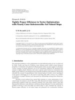
Figure 1: Filter bank system model with time/frequency compensation at subchannel level.
multiuser OFDM (OFDMA) have been considered in [6–10].
The idea of achieving perfect compensation of the carrier and
time offsets in multiuser FMT has been also applied for the
development of the synchronization metrics in [12].
However, perfect synchronization is not the optimal
choice. In fact, in the uplink each user experiences its own
channel, time offset, and carrier frequency offset. Thus,
the receiver may suffer of the presence of multiple access
interference (MAI), as well as intercarrier interference (ICI)
and intersymbol interference (ISI) [1, 6–8]. To maximize
performance the synchronization parameters h ave to be
chosen to maximize the sig n al-to-interference-plus-noise
ratio (SINR) at the detection point in each subchannel.
We show that it is possible to implement different receiver
filter bank (FB) structures depending on the specific SINR
criterion adopted, which leads to the use of
(a) a subchannel synchronized filter bank if the goal is to
maximize the subchannel SINR,
(b) a user synchronized filter bank if the go al is to
maximize a user-defined SINR,
(c) a single filter bank for all users if the goal is to
maximize an aggregate SINR,
(d) a fractionally spaced filter bank w ith partial compen-
sation of the carrier frequency offsets.
All these receivers deploy maximum SINR subchannel
equalization to deal with the subchannel ISI. Although
thereceiver(a)isoptimal,itsuffers of high complexity
because it needs to run an exhaustive search of the optimal
parameters to compensate the time and frequency offset for
each subchannel. Furthermore, the implementation of the
analysis filter bank cannot exploit the efficient polyphase
discrete Fourier transform (DFT) filter bank realizations
described in [3, 4] that require a common sampling phase for
all the subchannels. Lower complexity is obtained with the
receiver (b) and (c), although the synchronization metric still
requires an exhaustive search of the synchronization param-
eters. We then show that a relaxation of the aggregate SINR
metric allows implementing an efficient multiuser analysis
filter bank where the synchronization strategy consists in
deploying a common time phase for all the users and in
performing a partial correction of the frequency offsets. In
this receiver, two frac tionally spaced analysis stages are used.
Each analysis stage is efficiently implemented via a polyphase
DFT filter bank, followed by an extended DFT that allows the
user frequency offsets to be partly compensated. This receiver
has been already proposed in [12] with, however, a different
synchronization metric and w ithout the use of maximum
SINR subchannel equalization. Furthermore, in this paper
we discuss the application not only to multiuser FMT (as it
was done in [12]) but also to OFDMA.
This paper is organized as follows. In Section 2,we
describe the system model and the equalization scheme. In
Section 3, we discuss synchronization based on maximum
SINR, the efficient receiver analysis filter bank, and the appli-
cation to FMT and OFDMA. A detailed derivation of the
maximum SINR (MSINR) subchannel equalizer is reported
in the appendix where we also discuss the relation with the
minimum-mean-square-error (MMSE) equalization solu-
tion. The performance results are reported in Section 4. They
show that, for the considered simulation scenario, multiuser
EURASIP Journal on Wireless Communications and Networking 3
FMT performs better than OFDMA because of its better
subchannel spectral containment. Finally, in Section 5 we
draw the conclusions.
2. System Model
In a multiuser FBM system, the complex baseband signal
x
(u)
(nT)transmittedbyuseru is obtained by a filter bank
(FB) modulator with prototype pulse g(nT), for example, a
root-raised cosine pulse for FMT, and sub-carrier frequency
f
k
= k/(MT), k = 0, , M − 1; that is,
x
(u)
(
nT
)
=
k∈K
u
∈Z
a
(u,k)
(
T
0
)
g
(
nT
− T
0
)
e
j2πf
k
nT
=
k∈K
u
x
(u,k)
(
nT
)
,
(1)
where T is the sampling period, K
u
⊆{0, , M − 1} is the
set of tone indices assigned to user u,and
Z is the set of
integer numbers.
{a
(u,k)
(T
0
), ∈ Z} is the kth subchannel
data stream of user u that we assume to belong to the QPSK
signal set, and that has period T
0
= NT ≥ MT. With N
U
users, P = M/N
U
subchannels are assigned to each user. The
low-pass received signal is
y
(
iT
)
=
N
U
−1
u=0
k∈K
u
n∈Z
x
(u,k)
(
nT
)
g
(u)
CH
iT − nT − Δ
(k)
τ
×
e
j2πΔ
(k)
f
iT
+ η
(
iT
)
,
(2)
where Δ
(k)
τ
and Δ
(k)
f
are the time and frequency offsets of the
subchannel k assigned to user u. g
(u)
CH
(iT) is the fading chan-
nel impulse response of user u,andη(iT) is the zero mean
additive white complex Gaussian noise contribution. The
time/frequency offsets are identical for all the subchannels of
a given user, that is, Δ
(k)
τ
= Δ
τ,u
and Δ
(k)
f
= Δ
f ,u
,fork ∈ K
u
.
Assuming to deploy a single-user receiver approach, the
receiver (Figure 1) first compensates the frequency offset for
the subchannels of the desired user by an amount
Δ
(k)
f
; that is,
the received signal y( iT) is premultiplied by e
− j2π
Δ
(k)
f
iT
.Then,
it applies an analysis filter and it uses a subchannel time phase
Δ
(k)
τ
to correct the subchannel time offset. Its output for the
kth subchannel can be written as
z
(k)
mT
0
+
Δ
(k)
τ
=
i∈Z
y
(
iT
)
h
mT
0
− iT +
Δ
(k)
τ
e
− j2π( f
k
+
Δ
(k)
f
)iT
= e
j(2πβ
(k)
f
mT
0
+ϕ
(k)
)
a
(u,k)
(
mT
0
)
g
(k)
EQ
(
0
)
+ e
j(2πβ
(k)
f
mT
0
+ϕ
(k)
)
m
/
=
a
(u,k)
(
T
0
)
g
(k)
EQ
(
mT
0
− lT
0
)
+ICI
(k)
mT
0
+
Δ
(k)
τ
+MAI
(k)
mT
0
+
Δ
(k)
τ
+ η
(k)
mT
0
+
Δ
(k)
τ
,
(3)
where β
(k)
f
= Δ
(k)
f
−
Δ
(k)
f
and ϕ
(k)
= 2π(β
(k)
f
Δ
(k)
τ
− f
k
Δ
(k)
τ
).
In (3) we have a term associated to the data symbol of
interest, plus ISI, ICI, MAI, and noise. Further, the equivalent
response of subchannel k of user u (that gives the ISI
coefficients) reads
g
(k)
EQ
(
mT
0
)
=
i∈Z
g
(u)
CH
(
iT
)
e
− j2πf
k
iT
×
n∈Z
g
nT − iT + mT
0
− Δ
(k)
τ
+
Δ
(k)
τ
×
h
(
−nT
)
e
j2πβ
(k)
f
nT
,
(4)
where k
∈ K
u
.
Thefilterbankoutputsatrate1/T
0
are firstly com-
pensated to remove the phase rotation introduced by
the residual carrier frequency offset β
(k)
f
, and then, they
are processed with subchannel equalizers that we design
according to the maximum SINR (MSINR) criterion. That
is, we determine the N
w
-length equalizer coefficients w
(k)
SINR
=
[
w
(k)
0
w
(k)
1
··· w
(k)
N
w
−1
]
T
(where (·)
T
denotes the transpose opera-
tor), that maximize the output SINR (see appendix)
SINR
(k)
Δ
(k)
τ
,
Δ
(k)
f
=
P
(k)
U
Δ
(k)
τ
,
Δ
(k)
f
P
(k)
I
Δ
(k)
τ
,
Δ
(k)
f
+ P
(k)
η
Δ
(k)
τ
,
Δ
(k)
f
,
(5)
where P
(k)
U
, P
(k)
I
,andP
(k)
η
are the useful term average power,
the interference and the noise power, at the equalizer output,
respectively. These quantities, and thus the SINR at the
equalizer output, depend on the synchronization parameters
Δ
(k)
τ
,and
Δ
(k)
f
.
The SINR criterion, for given values of
Δ
(k)
τ
and
Δ
(k)
f
,
yields the following solution for the equalizer coefficients
w
(k)
SINR
=
R
(k)
SINR
−1
p
(k)
d
,(6)
where R
(k)
SINR
= R
(k)
ISI
+ R
(k)
ICI+MAI
+ R
(k)
η
is the N
w
× N
w
corre-
lation matrix of the interference-plus-noise term that com-
prises ISI, ICI, MAI, and noise, while p
(k)
d
= [g
(k)
EQ
(dT
0
),
, g
(k)
EQ
((N
w
+ d − 1)T
0
)]
T
is the subchannel response vector
whose components are given by the equivalent impulse
response coefficients in (4). The latter is a function of the
total delay d of the system. The detailed derivation of the
MSINR equalizer is reported in appendix. In the appendix
we also report a proof that the maximum SINR solution
is equivalent to the minimum-mean-square error (MMSE)
equalizer solution [13] if, however, the ICI and MAI are taken
into account in the computation of the equalizer coefficients.
For given values of
Δ
(k)
τ
and
Δ
(k)
f
, the MSINR equalizer
yields the following output SINR (see appendix):
SINR
(k)
MAX
Δ
(k)
τ
,
Δ
(k)
f
=
p
(k)
d
H
R
(k)
SINR
−1
p
(k)
d
,(7)
where (
·)
H
denotes the Hermitian operator, and for ease of
notation, we do not explicitly show the dependency of the
4 EURASIP Journal on Wireless Communications and Networking
correlation matrix and of the subchannel response vector
from
Δ
(k)
τ
and
Δ
(k)
f
.
Now, in OFDM [2] the synthesis pulse is g(nT)
=
rect(nT/T
0
) while the analysis pulse is h(nT) = rect(−(n +
μ)T/MT), where the rectangular pulse is defined as rect(t)
=
1for0≤ t<1, and zero otherwise. μ = N − M is the cyclic
prefix (CP) length in samples. The efficient implementation
of OFDM is done with an inverse DFT (IDFT) plus the
insertion of the CP at the transmitter. At the receiver, after
synchronization, the CP is discarded and a DFT is applied.
Commonly, one-tap subchannel equalization is used. In the
multiuser channel, orthogonality can be preserved for the
subchannels of the desired user. However, MAI is introduced
when the other users’ have distinct carrier frequency offsets,
and propagation delays plus channel dispersion in excess of
the CP length [7].
In FMT [3], the subchannel symbol period is T
0
=
NT. The analysis pulse is matched to the synthesis pulse,
that is, h(nT)
= g
∗
(−nT). The peculiarity is that the
subchannels are shaped with time-frequency concentrated
pulses, for example, root-raised-cosine pulses. This allows
minimizing the ICI and therefore the MAI. Linear subchan-
nel equalization, as described above, is used to cope with the
residual subchannel ISI. The analysis FB can be efficiently
implemented via polyphase filtering followed by an M-point
DFT [3, 4] provided that the subchannel analysis pulses are
identical and the time/frequency compensation is identical
for all the subchannels.
3. Maximum S INR Synchronization Metrics
The choice of the synchronization parameters affects not
only the performance but also the implementation complex-
ity of the receiver as discussed in the following.
The most intuitive thing we can do is to compensate the
time and frequency offset for each user with the exact value
of the misalignments; that is,
Δ
(k)
τ
= Δ
τ,u
and
Δ
(k)
f
= Δ
f ,u
for
k
∈ K
u
. As shown in Section 4, this baseline receiver (BL-RX)
may yield suboptimal performance. Therefore, the criterion
herein considered is to choose
Δ
(k)
τ
and
Δ
(k)
f
such that the
SINR in ( 5) or an average SINR is maximized.
The best approach is to perform synchronization at sub-
channel level, that is, we use for each subchannel an optimal
value for the parameters. This is because in the presence of
frequency selective fading the channel responses vary across
the subchannels. Further, each subchannel experiences a
different amount of MAI which depends on the realization of
the time/frequency offsets of the other subchannels assigned
to the users. Therefore, for each subchannel k belonging
to user u, we have to find the frequency offset
Δ
(k)
f
and
the sampling phase
Δ
(k)
τ
that maximize the SINR (5) at the
output of the subchannel equalizer; that is,
Δ
(k)
τ
,
Δ
(k)
f
=
arg max
−1/
(
2MT
)
<Δ
f
<1/
(
2MT
)
−NT≤Δ
τ
≤NT
SINR
(k)
Δ
τ
, Δ
f
. (8)
In ( 8) we assume
|
Δ
(k)
f
| < 1/(2MT), so that adjacent sub-
channels do not completely overlap. Moreover, we assume
that we have performed a coarse time synchronization, so
we can bound the sampling phase search in the interval
[
−NT, NT], corresponding to twice the symbol period.
It should be noted that there are two sources of
complexity. First, the exhaustive search of the optimal
parameters according to (8) is a heavy task. It implies the
direct computation of the maximum SINR a t the subchannel
equalizer output according to (7) for each possible value of
Δ
(k)
τ
and
Δ
(k)
f
. Second, we cannot process all the subchannels
with an efficient polyphase DFT analysis FB since this
requires a common time/frequency compensation for all the
subchannels [3, 4]. If we assume the prototype pulse to
have length LN coefficients, the complexity of the receiver
filter bank is in the order of 2MLN
2
/T
0
complex operations
(addition and multiplications) per second.
To lower the complexity, we have to use a common sam-
pling phase and a common frequency offset compensation
for all the subchannels assigned to the user. This receiver is
referred to as User Synchronized Receiver (US-RX) and it
deploys the para meters obtained by maximizing the average
user SINR as follows:
Δ
(u)
τ
,
Δ
(u)
f
=
arg max
−1/
(
2MT
)
<Δ
f
<1/
(
2MT
)
−NT≤Δ
τ
≤NT
⎡
⎣
k∈K
u
SINR
(k)
Δ
τ
, Δ
f
⎤
⎦
.
(9)
We note that according to (9) we do not necessarily
completely compensate the time and frequency offset of
the user of interest. This is the case only in the absence
of MAI because in such a case the SINR equals the SNR
which is maximized with an analysis FB perfectly matched
to the synthesis FB. It should be noted that also this
synchronization strategy requires an exhaustive joint search
of the optimal synchronization parameters (
Δ
(u)
τ
,
Δ
(u)
f
)and
the computation of the SINR has to be done at sampling
rate 1/T. In other words, during the synchronization stage
we cannot implement the analysis filter bank in an efficient
manner. On the contrary, during the detection stage the
received signal is time/frequency precompensated with the
use of the estimated parameters (
Δ
(u)
τ
,
Δ
(u)
f
) and analyzed
with a filter bank that can be efficiently implemented via
polyphase filtering and a DFT [3, 4]. However, we still need
to run one analysis FB per user. The DFT filter bank is
discussed in Section 3.1 and 3.2.
It would be beneficial to use a unique analysis FB that
allowed the detection of all users’ signals. To do so we have to
find a common sampling phase
Δ
τ
and a common frequency
offset compensation by
Δ
f
for all the users. This can be done
by maximizing the aggregate SINR as follows:
Δ
τ
,
Δ
f
=
arg max
−1/
(
2MT
)
<Δ
f
<1/
(
2MT
)
−NT<Δ
τ
<NT
⎡
⎣
M−1
k=0
SINR
(k)
Δ
τ
, Δ
f
⎤
⎦
.
(10)
In the following, this receiver is referred to as Multiuser
Analysis FB (MU-FB).
EURASIP Journal on Wireless Communications and Networking 5
3.1. Efficient Implementation of the Multiuser Analysis Filter
Bank. As explained in the previous section, the most efficient
solution (in terms of implementation complexity) is the
MU-FB, where all the users’ signals are detected by a single
analysis bank using the same sampling phase
Δ
τ
and the same
frequency offset compensation by
Δ
f
for all the subchannels.
An efficient implementation of this receiver is possible, and
it has been proposed in [12]. For clarity we summarize
the main steps and we further extend the results. It is
obtained via the polyphase decomposition of the received
signal (after time and f requency compensation) with period
T
2
= M
2
T,whereM
2
= .c.m.(M, N) = K
2
M = L
2
N,and
.c.m.(M, N) is the least common multiple between M and
N. The polyphase decomposition of the received signal can
be written as
y
(i)
(
L
2
T
0
)
= y
iT + L
2
T
0
+
Δ
τ
e
− j2π
Δ
f
(iT+L
2
T
0
)
,
i
= 0, , M
2
− 1.
(11)
Since f
k
= k/MT = K
2
k/M
2
T, the kth subchannel output is
computed as follows:
z
(k)
(
mT
0
)
=
M
2
−1
i=0
Z
(i)
(
mT
0
)
e
− j(2πK
2
/M
2
)ik
,
k
= 0, , M − 1,
Z
(i)
(
mT
0
)
=
∈Z
y
(i)
(
L
2
T
0
)
h
(−i)
(
mT
0
− L
2
T
0
)
,
(12)
where h
(−i)
(mT
0
) = h(mT
0
− iT) is the ith polyphase pulse
component. According to (12) the efficient realization com-
prises the following steps: compensate the time/frequency
offset, serial-to-parallel (S/P) convert the signal, interpolate
the M
2
polyphase components of the compensated signal by
afactorL
2
, analyze them with the low-rate filters h
(−i)
(mT
0
),
apply an M
2
-point DFT, and sample the outputs of index
K
2
k. The indices k ∈ K
u
are those associated to the
subchannels of user u.
We note that we can relax the constraint of having
an identical frequency offset compensation for all the
subchannels by simply exploiting the frequency resolution
provided by the DFT. To do this, we first define M
3
= QM
2
=
K
3
M = L
3
N,whereQ is a positive integer. Then, we split the
subchannel frequency offset in an integer part, multiple of
1/M
3
T, and a fractional part
Δ
(k)
f
; that is,
Δ
(k)
f
=
q
(k)
M
3
T
+
Δ
(k)
f
. (13)
In the following we assume
|q
(k)
| < K
3
/2, so that adjacent
subchannels do not completely overlap. Further more, we
assume to compensate, before the FB, only the integer part
of the frequency offset, and to sample the subchannel filter
output at time instant mT
0
+
Δ
τ
. Therefore, the subchannel
output of index k is
z
(k,q
(k)
)
mT
0
+
Δ
τ
=
i∈Z
y
(
iT
)
e
− j2π( f
k
+(q
(k)
/M
3
T))iT
× h
mT
0
+
Δ
τ
− iT
=
e
j(2π
Δ
(k)
f
mT
0
+ϕ
(k)
)
a
(u,k)
(
mT
0
)
g
(k)
EQ
(
0
)
+ I
(k)
mT
0
+
Δ
τ
,
(14)
where ϕ
(k)
= 2π(
Δ
(k)
f
Δ
τ
− f
k
Δ
(k)
τ
). It comprises a useful
term plus an interference term due to ISI, ICI, MAI, and
noise. Furthermore, the subchannel equivalent response of
subchannel k
∈ K
u
of user u reads
g
(k)
EQ
(
mT
0
)
=
i∈Z
g
(u)
CH
(
iT
)
e
− j2πf
k
iT
×
n∈Z
g
nT − iT + mT
0
− Δ
(k)
τ
+
Δ
τ
×
h
(
−nT
)
e
j2π
Δ
(k)
f
nT
.
(15)
The factor e
j2π
Δ
(k)
f
mT
0
in (14) introduces a time-variant
rotation of the constellation, but it can be fully compensated
at the subchannel filter output before passing the samples
to the equalizer. The factor e
j2π
Δ
(k)
f
nT
in (15) cannot be
compensated, and it yields a frequency mismatch between
the received subchannel and the analysis subchannel filter.
Therefore, the compensation of only the integer part of the
frequency offset translates in both a subchannel SNR loss,
and increased ISI. However, as it is shown in Section 4, the
penalty in performance can be negligible for practical values
of frequency offset, that is, when
Δ
(k)
f
nT is small over the
duration of the prototype pulse.
The correction of the integer part of the frequency offset
can be included in the efficient implementation. If we apply
the polyphase decomposition to (14) with period M
3
T,we
obtain
z
(k,q
(k)
)
mT
0
+
Δ
τ
=
M
3
−1
i=0
Y
(i)
mT
0
+
Δ
τ
×
e
− j(2π(K
3
k+q
(k)
)/M
3
)i
,
(16)
with
Y
(i)
mT
0
+
Δ
τ
=
∈Z
y
(i)
L
3
T
0
+
Δ
τ
×
h
(−i)
(
mT
0
− L
3
T
0
)
y
(i)
L
3
T
0
+
Δ
τ
=
y
iT + L
3
T
0
+
Δ
τ
,
i
= 0, , M
3
− 1.
(17)
According to (16)and(17), the efficient realization com-
prises the following steps (see also Figure 2): S/P conversion,
6 EURASIP Journal on Wireless Communications and Networking
S/P
y(iT + T
0
/2)
DFT
M
3
points
P/S
P/S
M
3
T
FS equalizer
channel 0
FS equalizer
channel M
− 1
Fractional frequency
offset correction
Select M channels
with frequency shift
(integer frequency
offset correction)
Efficient analysis filter bank with
integer frequency offset correction
FMT demodulator for 0 delay branch
FMT demodulator for T
0
/2delaybranch
T
0
/2
delay
L
3
L
3
T
0
T
0
T
T
0
T
0
T
0
.
.
.
.
.
.
.
.
.
x
x
T
0
/2
T
0
/2
.
.
.
.
.
.
h
(0)
(lT
0
)
z
(0)
(lT
0
)
z
(M−1)
(lT
0
)
e
− j2πβ
(0)
f
lT
0
/2
e
− j2πβ
(M−1)
f
lT
0
/2
z
(M−1)
(lT
0
+ T
0
/2)
z
(0)
(lT
0
+ T
0
/2)
a
(0)
(lT
0
)
a
(M−1)
(lT
0
)
h
(−M
3
+1)
(lT
0
)
y
(0)
(·)
y
(M
3
−1)
(·)
Y
(0)
(·)
Y
(M
3
−1)
(·)
y(iT)
β
(k)
f
=
Δ
(u)
f
, kK
u
Figure 2: Multiuser analysis filter bank receiver.
interpolation by a factor L
3
, filtering with the polyphase
pulses h
(−i)
(mT
0
), computation of an M
3
-point DFT, and
sampling the DFT outputs with index K
3
k + q
(k)
for k ∈ K
u
.
Finally, we compensate the fractional frequency offset with
the multiplication by e
− j2π
Δ
(k)
f
mT
0
at the DFT stage output;
that is, we remove the time variant phase shift of the signal at
the subchannel equalizer input. Note that the correction of
the integer part of the frequency offsetisdonebychoosing
the appropriate output tone of the M
3
-point DFT (shifted
tone). With perfect compensation of the fractional frequency
offset, the subchannel equalizer does not see any residual
frequency offset; therefore, it is implemented with a static
filter over a given burst of data symbols. In the presence of
channel time variations, adaptation can also be performed at
a symbol-by-symbol level.
With this efficient implementation, we have devised a
unique FB that allows the choice of different frequency offsets
(multiple of the DFT frequency resolution 1/M
3
T) for the
different subchannels. Therefore, the synchronization metric
(10) can be generalized as follows:
Δ
τ
, q
=
arg max
−K
3
/2≤q<K
3
/2
−
NT<Δ
τ
<NT
⎡
⎣
M−1
k=0
SINR
(k)
Δ
τ
, q
(k)
⎤
⎦
, (18)
where q
= [q
(0)
, , q
(M−1)
] is the vector with components
satisfying
|q
(k)
|≤K
3
/2 for all k ∈{0, , M − 1}. The
metric (18) corresponds to find the sampling phase
Δ
τ
and
the set of integer parameters
q = [q
(0)
, , q
(M−1)
] that
maximize the aggregate SINR. Moreover, differently from
(8), (9), and (10) that require the maximization over an
infinite set of frequency offsets, the search in (18)canbedone
over a discrete and finite set of q values.
In the next section, we specialize the MU-FB to two
schemes of practical interest, that is, FMT and OFDM. We
propose a further simplification for FMT that allows using
a fractionally spaced analysis filter bank during both the
synchronization stage and the detection stage.
3.2. Application of the MU-FB to FMT Systems. Since in FMT
the subchannels are frequency confined, a w rong time phase
may introduce increased subchannel ISI but it does not,
ideally, introduce ICI. Therefore, instead of searching the
time phase according to (18) (which has to be done at least
with resolution equal to the sampling period T), we propose
to deploy two multiuser analysis FBs, the first with a fixed
sampling phase
Δ
τ
= 0, and the second with
Δ
τ
= T
0
/2. The
outputs of the two FBs are processed by fractionally spaced
linear subchannel equalizers [13], as shown in Figure 2.
They are designed according to the MSINR criterion (see
appendix). In this case, (18) reduces to the independent
search of the parameters
q
(k)
as follows:
q
(k)
= arg max
−K
3
/2≤q<K
3
/2
SINR
(k)
F
q
, (19)
where SINR
(k)
F
(q) is the output SINR of the fractionally
spaced equalizer applied to subchannel k assuming a fre-
quency offset compensation equal to q/M
3
T.
Extending the result in (6)and(7) (see appendix), the
MSINR fractionally spaced equalizer solution is given by
w
(k)
F,SINR
=
R
(k)
F,SINR
−1
p
(k)
F,d
, (20)
while
SINR
(k)
F
q
=
p
(k)
F,d
H
R
(k)
F,SINR
−1
p
(k)
F,d
, (21)
where R
(k)
F,SINR
is the 2N
w
× 2N
w
correlation matrix of the
interference-plus-noise term that comprises ISI, ICI, and
MAI, while p
(k)
F,d
is the subchannel response vector whose
components are given by the equivalent impulse response
coefficients (15)sampled,however,atrate2/T
0
, that is,
p
(k)
F,d
= [g
(k)
EQ
(dT
0
/2), , g
(k)
EQ
((2N
w
+ d − 1)T
0
/2)]
T
.
If the amount of the interference is small, the optimal
q
(k)
valueisobtainedasfollows:
q
(k)
= arg min
−K
3
/2≤q<K
3
/2
Δ
(k)
f
−
q
M
3
T
, (22)
that corresponds to minimize the fractional par t of the
frequency offset at the output of the receiver FB; that is,
we compensate almost perfectly the frequency offset. This
metric that was used in [12], is simpler than (19), but
EURASIP Journal on Wireless Communications and Networking 7
it provides, in general, lower performance as shown in
Section 4.
It should b e noted that now both the synchroniza-
tion stage and the detection stage enjoy the same effi-
cient implementation of the fractionally spaced analysis
filter bank whose complexity is in the order of 2(2LN +
QM
2
log
2
(QM
2
) − QM
2
)/T
0
operations per second. On the
contrary, the US-RX enjoys the efficient implementation
only during the detection stage which is equal to N
U
(2LN +
M
2
log
2
(M
2
) − M
2
)/T
0
operations per second for the overall
N
U
users. Therefore, also during the detection stage the US-
RX can be more complex than the fractionally spaced MU-
RX depending on the choice of the parameters. For instance,
with M
= 32, N = 40, L = 6, and N
U
= 8, the filter bank
in the SU-RX during synchronization has complexity 15360
operation/s while it has complexity 298 operation/s during
detection. The MU-RX analysis filter bank has complexity
both during synchronization and detection equal to 74, 290,
620 operations/s, respectively, for Q
= 1, 4, 8.
3.3.ApplicationoftheMU-FBtoOFDMSystems.As it is
known, the OFDM systems are extremely sensitive to time
and frequency misalignments [6–8]. This is due to the fact
that the prototype pulse has a sinc frequency response. Thus,
differently from FMT, it does not provide a high frequency
confinement. To provide robustness we may synchronize
the users in the downlink frame and deploy a CP that is
longer than the channel time dispersion plus the maximum
delay of the users [7]. Under this assumption, we can use a
common
Δ
τ
for all the users that is equal to the sampling
phase that synchronizes the receiver to the user with the
minimum delay. Thus, differently from the FMT case, we can
use a single multiuser analysis FB, and the choice of the set
of parameters
q can be independently performed from
Δ
τ
according to (19).
It should be noted that, in the OFDM case, the imple-
mentation of the multiuser analysis FB herein proposed,
comprises the following steps. First, we acquire synchroniza-
tion with the user having minimum delay and we discard
the CP. Then, we zero pad the frame of Mreceived samples
to obtain a frame of M
3
samples, and we apply an M
3
-point
DFT.
Finally, we point out that to mitigate the MAI interfer-
ence in OFDMA, some multiuser detection approach may be
necessary, for example, maximum likelihood [1]detection
or linear multichannel [14] e qualization. This, however,
increases complexity.
4. Performance Results
We now compare the performance of the various synchro-
nization metrics. We first consider 8 asynchronous users,
M
= 32 tones that are regularly interleaved across the users
both in the FMT and the OFDM systems. To obtain the
same transmission rate, we use an interpolation factor of
N
= 40 in FMT, and a CP = 8 samples in OFDM. In
the FMT system, the prototype pulse has duration 12T
0
,
and it is designed according to [4] to achieve a theoretical
00.04 0.08 0.12 0.16 0.2
10
−3
10
−2
10
−1
Bit error rate (BER)
SNR=30 dB
SCS-RX, synchronous users
FMT. 8 users. fully allocated.
BL-RX, T
0
spaced equalizer
BL-RX, T
0
/2 spaced equalizer
ε
f
= Δ
max
f
· MT
Δ
max
τ
=NT
MU-FB, Q
= 1, metric (22)
MU-FB, Q = 4, metric (22)
MU-FB, Q
= 8, metric (22)
MU-FB, Q
= 1, metric (19)
MU-FB, Q
= 4, metric (19)
MU-FB, Q
= 8, metric (19)
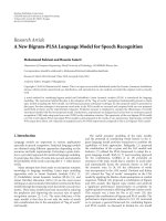
Figure 3: BER as a function of frequency offset. 8 interleaved
users fully allocated. Comparison of the compensation metrics for
different values of Q. FMT with M
= 32 and N = 40.
bandwidth equal to 1.25/T
0
= 1/MT. We assume the
carrier frequency offsets to be independent and uniformly
distributed in [
−Δ
max
f
, Δ
max
f
], while the time offsets to be
uniformly distributed in [0, Δ
max
τ
], with Δ
max
τ
= NT. The
user channels are assumed to be Rayleigh faded with an
exponential power delay profile with independent T-spaced
taps that have average power Ω
p
∼ e
−pT/(0.05T
0
)
with p ∈
Z
+
and t runcation at −20 dB. Perfect knowledge of the
parameters (time/frequency offsets) and channel responses is
assumed. QPSK modulation is used. OFDM performs one-
tap equalization, while FMT deploys three taps subchannel
equalization. The average bit error rate (BER) is obtained by
averaging the BER of all the users over bursts of duration 100
symbols.
In Figures 3
−6 we plot the BER as function of the
maximum carrier frequency offset. The SNR is set to 30 dB.
The SNR includes the loss in OFDM due to the cyclic prefix.
We compare the performance obtained with the base line
receiver (BL-RX) to the performance of the MU-FB receiver
that uses the metric (19), labelled w ith “metric (19)”, or the
metric (22), labelled with “metric (22)”. For the FMT case
the BL-RX uses a T
0
spaced equalizer or a T
0
/2 fractionally
spaced equalizer. The BL-RX is a single-user receiver that
performs perfect compensation of the time/frequency offset
for the user of interest. As discussed in Section 3, the BL-RX
is identical to the US-RX in the absence of MAI. Therefore,
for small carrier frequency offsets the performance of the two
8 EURASIP Journal on Wireless Communications and Networking
00.04 0.08 0.12 0.16 0.2
10
−3
10
−2
10
−1
Bit error rate (BER)
SNR=30 dB
SCS-RX, synchronous users
BL-RX
OFDM. 8 users. fully allocated.
ε
f
= Δ
max
f
· MT
Δ
max
τ
=NT
MU-FB, Q
= 1, metric (22)
MU-FB, Q
= 4, metric (22)
MU-FB, Q
= 8, metric (22)
MU-FB, Q
= 1, metric (19)
MU-FB, Q
= 4, metric (19)
MU-FB, Q = 8, metric (19)
Figure 4: BER as a function of frequency offset. 8 interleaved
users fully allocated. Comparison of the compensation metrics for
different values of Q. OFDM with M
= 32 and CP = 8.
00.04 0.08 0.12 0.16 0.2
10
−3
10
−2
10
−1
Bit error rate (BER)
FMT. 4 users. half allocated.
BL-RX, T
0
spaced equalizer
BL-RX, T
0
/2 spaced equalizer
ε
f
= Δ
max
f
· MT
MU-FB, Q
= 1, metric (22)
MU-FB, Q
= 4, metric (22)
MU-FB, Q
= 8, metric (22)
MU-FB, Q
= 1, metric (19)
MU-FB, Q
= 4, metric (19)
MU-FB, Q = 8, metric (19)
SNR
=30 dB
Δ
max
τ
=NT
Figure 5: BER as a function of frequency offset. 8 interleaved
users with only 4 nonadjacent active users. Comparison of the
compensation metrics for different values of Q. FMT with M
= 32
and N
= 40.
BL-RX
0
0.04 0.08 0.12 0.16
0.2
10
−3
10
−2
10
−1
Bit error rate (BER)
OFDM. 4 users. half allocated.
SNR
=30 dB
Δ
max
τ
=NT
ε
f
= Δ
max
f
· MT
MU-FB, Q
= 1, metric (22)
MU-FB, Q
= 4, metric (22)
MU-FB, Q = 8, metric (22)
MU-FB, Q
= 1, metric (19)
MU-FB, Q
= 4, metric (19)
MU-FB, Q = 8, metric (19)
Figure 6: BER as a function of frequency offset. 8 interleaved
users with only 4 nonadjacent active users. Comparison of the
compensation metrics for different values of Q. OFDM with M
=
32 and CP = 8.
receivers in the FMT system, is similar since the subchannels
exhibit a good frequency confinement.
The curve labelled with “SCS-RX, synchronous users”
shows the performance with synchronous users and with
theuseofmetric(8). It essentially shows the best attainable
performance.
The MU-FB with the metric that maximizes the SINR
(metric (19)) performs well for all the range of frequency
offsets both for FMT and OFDM. Especially for high values
of ε
f
= Δ
max
f
MT it performs better than with the metric that
minimizes the residual frequency offset (metric (22)) which
does not take into account the presence of MAI. Further,
the performance of the MU-FB with metric (19)improves
as Q increases. This is because a hig her frequency resolution
is provided and therefore improved compensation capability
of the carrier frequency offsets is obtained. FMT provides
significant better BER performance than OFDM due to its
better subchannel spectr a l containment that reduces the
effect of the MAI.
In Figures 5
−6 we consider the same scenario of Figures
3
−4 but only 4 nonadjacent users, with 4 tones each, are active
(users number 1, 3, 5, 7). In this case the MAI is significantly
reduced because each tone has two null adjacent tones. FMT
is essentially not affected by the carrier frequency offsets,
while OFDM still exhibits a high BER penalty. The MU-FB
and the BL-RX with a T
0
/2 fractionally spaced equalizer in
FMT have similar perfor mance w hile in OFDM the MU-FB
provides performance gains.
EURASIP Journal on Wireless Communications and Networking 9
SCS-RX, synchronous users
6 12182430
10
−3
10
−2
10
−1
10
−4
Bit error rate (BER)
SNR
8 users. fully allocated.
Solid: FMT
Dashed: OFDM
BL-RX, T
0
spaced equalizer
BL-RX, T
0
/2 spaced equalizer
= 0.12/(MT)
Δ
max
f
MU-FB, Q = 1, metric (19)
MU-FB, Q
= 4, metric (19)
MU-FB, Q = 8, metric (19)
Figure 7: BER as a function of SNR. 8 interleaved users fully
allocated. FMT with M
= 32 and N = 40. OFDM w ith M = 32
and CP
= 8.
In Figure 7 we plot the average BER as a function of the
SNR. We consider 8 users fully allocated and a maximum
frequency offset Δ
max
f
= 0.12/(MT). We show, both for
FMT and OFDM, the performance of metric (19)for
different values of Q. FMT has always better performance
and it exhibits lower error floors for high SNRs. We also
report the BER with synchronous users (curve labelled with
“SCS-RX, synchronous users”). In this case FMT has better
performance than OFDM because the subchannel equalizer
is capable of exploiting some frequency diversity.
5. Conclusions
In this paper we have discussed maximum SINR synchro-
nization in multiuser FBM systems. Perfect-user synchro-
nization is not necessarily optimal with single user detection.
The optimal subchannel synchronized receiver aims at
maximizing the SINR at subchannel level, but it is complex
and cannot enjoy an efficient DFT-based realization. Per-user
synchronization requires a bank of single-users receivers.
A single analysis filter bank c an be implemented if a
common compensation of the users time/frequency offset
is performed, for example, according to an aggregate SINR
criterion.
We have then proposed a suboptimal SINR metric
that allows the realization of a multiuser low complexity
fractionally spaced analysis FB combined with subchannel
MSINR fractionally spaced equalization. This receiver is in
principle applicable to any FBM system. We have discussed
its application to OFDMA and multiuser FMT. We have
highligh ted that it performs better with the novel MSINR
metric herein proposed than with the one used in [12] that
targets perfec t frequency offset compensation without taking
into account the presence of interference. Furthermore, sim-
ulation results show that FMT exhibits superior performance
than OFDMA since it has more robustness to the MAI due to
the better subchannel spectral containment.
Finally, we have reported (see appendix) a proof that the
maximum SINR subchannel equalizer is equal to the MMSE
subchannel equalizer if we take into account the presence of
interference.
Appendices
A. Linear Subchannel Equalizer Design
In this appendix we first report the derivation of the
maximum SINR equalizer. Then, we prove that this solution
is equivalent to the MMSE one; that is, the MMSE criterion
for channel equalization design maximizes the SINR at the
equalizer output provided that the presence of ICI and ISI is
taken into account.
A.1. Maximum SINR Subchannel Equalizer. The signal at the
equalizer output can be written as follows. (E[
·] denotes the
expectation operator.)
a
(k)
m
= a
(k)
(
mT
0
)
=
w
(k)
H
z
(k)
m
,(A.1)
where w
(k)
=
[
w
(k)
0
w
(k)
1
w
(k)
N
w
−1
]
T
is a column vector con-
taining the N
w
coefficients of the equalization filter, while
z
(k)
m
=
z
(k)
m
z
(k)
m
−1
z
(k)
m
−(N
w
−1)
T
is a column vector containing the
samples at the subchannel equalizer input that are given by
(3) after the compensation of the residual carrier frequency
offset via multiplication by e
− j(2πβ
(k)
f
mT
0
+ϕ
(k)
)
. The vector z
(k)
m
can be written as follows:
z
(k)
m
=
M−1
k=0
P
(
k,k)
m
a
(
k)
m
+ η
(k)
m
,(A.2)
where P
(
k,k)
m
=
p
(
k,k)
m,1
p
(
k,k)
m,2
p
(
k,k)
m,N
p
+N
w
−1
is a Toeplitz matrix of
size [N
w
× (N
p
+ N
w
− 1)] containing the coefficients of the
equivalent cross-channel impulse response, at time instant
m, between the input subchannel of index
k and the output
subchannel of index k in the system, which can be obtained
with a generalization of (4) (see also the Appendix A in [12])
and which is assumed to have duration N
P
coefficients. The
column vector a
(k)
m
= [a
(k)
m+N
P
/2−1
a
(k)
m
−1
a
(k)
m
−N
P
/2−N
w
+1
]
T
contains the transmitted data symbols that are assumed to be
independent, with zero mean, and with unitary power, that
is, E[a
(k)
m
(a
(k)
m
)
H
] = I
N
P
+N
w
−1
,whereI
N
P
+N
w
−1
is an identity
matrix of size N
P
+ N
w
− 1. In general, the noise vector of
samples has correlation E[η
(k)
m
(η
(k)
m
)
H
] = R
(k)
η
. Assuming the
analysis prototype pulse to be a Nyquist pulse and the input
noise to be white Gaussian, we have that R
(k)
η
= N
0
I
N
w
.
10 EURASIP Journal on Wireless Communications and Networking
Substituting (A.2)in(A.1) and assuming a total delay of
d samples in the system, we have
a
(k)
m
=
N
w
−1
n=0
w
∗
n
z
(k)
m
−n
=
w
(k)
H
⎛
⎝
M−1
k=0
P
(
k,k)
m
a
(
k)
m
+ η
(k)
m
⎞
⎠
=
w
(k)
H
p
(k)
d
a
(k)
m
−d
useful signal
+
/
= d
w
(k)
H
p
(k)
a
(k)
m
−
ISI
+
k
/
= k
w
(k)
H
P
(
k,k)
m
a
(
k)
m
ICI and MAI
+
w
(k)
H
η
(k)
m
noise
,
(A.3)
where p
(k)
d
= [g
(k)
EQ
(dT
0
), , g
(k)
EQ
((N
w
+ d − 1)T
0
)]
T
has ele-
ments given by (4).
To derive the equalizer that maximizes the SINR, we
start from the computation of the signal-to-interference-
plus-noise ratio at the equalizer output. From (A.3), the
useful signal power, for a given delay d,is
P
(k)
U
=
w
(k)
SINR
H
p
(k)
d
p
(k)
d
H
w
(k)
SINR
. (A.4)
The noise plus interference power is
P
(k)
I
+ P
(k)
η
=
/
= d
w
(k)
SINR
H
p
(k)
p
(k)
H
w
(k)
SINR
ISI
+
k
/
= k
w
(k)
SINR
H
P
(
k,k)
m
P
(
k,k)
m
H
w
(k)
SINR
ICI and MAI
+
w
(k)
SINR
H
R
(k)
η
w
(k)
SINR
noise
.
(A.5)
Then, the SINR can be wr itten as follows:
SINR
(k)
=
(
D
)
H
R
(k)
U
D
(
D
)
H
R
(k)
ISI
D +
(
D
)
H
R
(k)
ICI+MAI
D +
(
D
)
H
R
(k)
η
D
,
(A.6)
where D denotes w
(k)
SINR
, R
(k)
U
= p
(k)
d
(p
(k)
d
)
H
, R
(k)
ISI
=
/
= d
p
(k)
(p
(k)
)
H
,andR
(k)
ICI+MAI
=
k
/
= k
P
(
k,k)
m
(P
(
k,k)
m
)
H
that
does not depend on the time index m.
Now, we define R
(k)
SINR
as the sum of the correlation
matrices of the interference (ISI, ICI, and MAI) and the
noise; that is,
R
(k)
SINR
= R
(k)
ISI
+ R
(k)
ICI+MAI
+ R
(k)
η
. (A.7)
If we compute the Cholesky factor ization of the correlation
matrix [15], that is, R
(k)
SINR
= DD
H
, and we define the vector
u
= D
−1
p
(k)
d
,wecanrewrite(A.6)as
SINR
(k)
=
u
H
D
H
w
(k)
SINR
2
D
H
w
(k)
SINR
H
D
H
w
(k)
SINR
. (A.8)
Using the Cauchy-Schwarz inequality [15] the SINR is
maximum when u
∝ D
H
w
(k)
SINR
, and it is equal to SINR
(k)
=
u
H
u.
Equating the relations u
= D
−1
p
(k)
d
and u = D
H
w
(k)
SINR
,
we obtain the optimum solution for the equalizer coefficients
that is given by
w
(k)
SINR
=
DD
H
−1
p
(k)
d
=
R
(k)
SINR
−1
p
(k)
d
. (A.9)
Finally, the maximum SINR at the equalizer output is equal
to
SINR
(k)
MAX
= u
H
u =
p
(k)
d
H
R
(k)
SINR
−1
p
(k)
d
. (A.10)
A.2. Relation between the Maximum SINR and the MMSE
Equalizer. The MMSE equalizer [13] minimizes the error
between its output and the data symbol of interest a
(k)
m−d
;
that is, ε
m
= a
(k)
m
− a
(k)
m
−d
,whered is a certain delay, by
minimizing the quadratic for m J
= E[ε
m
ε
∗
m
]. The optimum
vector w
(k)
MMSE
is obtained from the orthogonality condition
E[ε
m
(z
(k)
m
)
H
] = 0 that corresponds to the following relation:
w
(k)
MMSE
H
E
z
(k)
m
z
(k)
m
H
=
E
a
(k)
m
−d
z
(k)
m
H
. (A.11)
The correlation matrix of the input is given by
R
(k)
MMSE
= E
z
(k)
m
z
(k)
m
H
=
M−1
k=0
P
(
k,k)
m
P
(
k,k)
m
H
+ R
(k)
η
,
(A.12)
while
E
a
(k)
m
−d
z
(k)
m
H
=
p
(k)
d
H
. (A.13)
Substituting (A.12)and(A.13)in(A.11), we obtain
w
(k)
MMSE
=
R
(k)
MMSE
−1
p
(k)
d
. (A.14)
Generalizing the results in [13] to take into account the
presence of ICI and MAI, the SINR at the output of the
MMSE equalizer is equal to
SINR
(k)
MMSE
=
p
(k)
d
H
R
(k)
MMSE
−1
p
(k)
d
1 −
p
(k)
d
H
R
(k)
MMSE
−1
p
(k)
d
. (A.15)
To prove the equivalence between the MMSE and the
maximum SINR equalizer we use the relation
R
(k)
SINR
= R
(k)
MMSE
− p
(k)
d
p
(k)
d
H
. (A.16)
EURASIP Journal on Wireless Communications and Networking 11
For the matrix inversion identity [16]wehave
R
(k)
MMSE
− p
(k)
d
p
(k)
d
H
−1
=
R
(k)
MMSE
−1
+
R
(k)
MMSE
−1
p
(k)
d
p
(k)
d
H
R
(k)
MMSE
−1
1 −
p
(k)
d
H
R
(k)
MMSE
−1
p
(k)
d
=
R
(k)
SINR
−1
.
(A.17)
Substituting (A.17)in(A.10)wecanwrite
SINR
(k)
MAX
=
p
(k)
d
H
R
(k)
MMSE
−1
p
(k)
d
+
p
(k)
d
H
R
(k)
MMSE
−1
p
(k)
d
p
(k)
d
H
R
(k)
MMSE
−1
p
(k)
d
1 −
p
(k)
d
H
R
(k)
MMSE
−1
p
(k)
d
=
p
(k)
d
H
R
(k)
MMSE
−1
p
(k)
d
1 −
p
(k)
d
H
R
(k)
MMSE
−1
p
(k)
d
= SINR
(k)
MMSE
,
(A.18)
which proves that the SINR at the MMSE equalizer output
is identical to the SINR at the maximum SINR equalizer
output. Furthermore, the vectors w
(k)
SINR
and w
(k)
MMSE
differ by
a constant factor as proved below:
w
(k)
SINR
=
R
(k)
MMSE
−1
p
(k)
d
+
R
(k)
MMSE
−1
p
(k)
d
p
(k)
d
H
R
(k)
MMSE
−1
p
(k)
d
1 −
p
(k)
d
H
R
(k)
MMSE
−1
p
(k)
d
= w
(k)
MMSE
1 + SINR
(k)
MMSE
.
(A.19)
Acknowledgments
The work of this paper has been partially supported by
the European Community Seventh Framework Programme
FP7/2007
−2013 under Grant agreement no. 213311, project
OMEGA-Home Gigabit Networks. The authors wish to
thank the anonymous reviewers whose comments helped to
improve the clarity of this paper.
References
[1] A. M. Tonello, “Asynchronous multicarrier multiple access:
optimal and sub-optimal detection and decoding,” Be ll Labs
Technical Journal, vol. 7, no. 3, pp. 191–217, 2003.
[2] S. Weinstein and P. Ebert, “Data transmission by frequency-
division multiplexing using the discrete Fourier transform,”
IEEE Transactions on Communications, vol. 19, no. 5, pp. 628–
634, 1971.
[3] G. Cherubini, E. Eleftheriou, and S.
¨
Olc¸er, “Filtered multitone
modulation for very high-speed digital subscriber lines,” IEEE
Journal on Selected Areas in Communications,vol.20,no.5,pp.
1016–1028, 2002.
[4] A. M. Tonello, “Time domain and frequency domain imple-
mentations of FMT modulation architectures,” in Proceedings
of IEEE International Conference on Acoustics, Speech and
Signal Processing (ICASSP ’06), vol. 4, pp. 625–628, Toulouse,
France, May 2006.
[5]T.M.SchmidlandD.C.Cox,“Robustfrequencyand
timing synchronization for OFDM,” IEEE Transactions on
Communications, vol. 45, no. 12, pp. 1613–1621, 1997.
[6] S. Kaiser and W. A. Krzymien, “Performance effects of the
uplink asynchronism in a spread spectrum multi-carrier
multiple access system,” European Transactions on Telecommu-
nications, vol. 10, no. 4, pp. 399–406, 1999.
[7] J J. van de Beek, P. O. B
¨
orjesson, M L. Boucheret et al., “Time
and frequency synchronization scheme for multiuser OFDM,”
IEEE Journal on Selected Areas in Communications, vol. 17, no.
11, pp. 1900–1914, 1999.
[8] A. M. Tonello, N. Laurenti, and S. Pupolin, “Analysis of
the uplink of an asynchronous multi-user DMT OFDMA
system impaired by time offsets, frequency offsets, and multi-
path fading,” in Proceedings of the 52nd Vehicular Technology
Conference (VTC ’00), pp. 1094–1099, Boston, Mass, USA,
September 2000.
[9] J. Choi, C. Lee, H. W. Jung, and Y. H. Lee, “Carrier frequency
offset compensation for uplink of OFDM-FDMA systems,”
IEEE Communications Letters, vol. 4, no. 12, pp. 414–416,
2000.
[10] Z. Cao, U. Tureli, and Y D. Yao, “Deterministic multiuser
carrier-frequency offset estimation for interleaved OFDMA
uplink,” IEEE Transactions on Communications, vol. 52, no. 9,
pp. 1585–1594, 2004.
[11] V. Lottici, M. Luise, C. Saccomando, and F. Spalla, “Non-data-
aided timing recovery for filter-bank multicarrier wireless
communications,” IEEE Transactions on Signal Processing, vol.
54, no. 11, pp. 4365–4375, 2006.
[12] A. M. Tonello and F. Pecile, “Synchronization algorithms
and receiver structures for multiuser filter bank uplink
systems,” EURASIP Journal on Wireless Communications and
Networking, vol. 2009, Article ID 387520, 17 pages, 2009.
[13] J. G. Proakis, Digital Communications, McGraw-Hill, New
York, NY, USA, 3rd edition, 1995.
[14] S W. Hou and C. C. Ko, “Multiple-access interference
suppression for interleaved OFDMA system uplink,” IEEE
Transactions on Vehicular Technology, vol. 57, no. 1, pp. 194–
205, 2008.
[15]R.A.HornandC.R.Johnson,Matrix Analysis, Cambridge
University Press, New York, NY, USA, 1990.
[16] M. Brookes, “The Matrix Reference Manual,” 2005, http://
www.ee.ic.ac.uk/hp/staff/dmb/matrix/intro.html
.