Báo cáo hóa học: " Research Article Class-Based Fair Code Allocation with Delay Guarantees for OVSF-CDMA and VSF-OFCDM in Next-Generation Cellular Networks" ppt
Bạn đang xem bản rút gọn của tài liệu. Xem và tải ngay bản đầy đủ của tài liệu tại đây (903.21 KB, 21 trang )
Hindawi Publishing Corporation
EURASIP Journal on Wireless Communications and Networking
Volume 2010, Article ID 738325, 21 pages
doi:10.1155/2010/738325
Research Ar ticle
Class-Based Fair Code Allocation with
Delay Guarantees for OVSF-CDMA and VSF-OFCDM in
Next-Generation Cellular Networks
Nara simha Challa and Hasan C¸am
Computer Science and Engineering Department, Arizona State University, Tempe, AZ 85287, USA
Correspondence should be addressed to Hasan C¸am,
Received 12 June 2010; Revised 30 September 2010; Accepted 15 November 2010
Academic Editor: Yuh Shyan Chen
Copyright © 2010 N. Challa and H. C¸ am. This is an open access article distributed under the Creative Commons Attribution
License, which permits unrestricted use, distribution, and reproduction in any medium, provided the original work is properly
cited.
This paper presents a novel class-based fair code allocation (CFCA) protocol to support delay and rate guarantees for real-
time flows and to provide fairness for non-real-time flows on the downlink of WCDMA- and VSF-OFCDM-based cellular
networks. CFCA not only assigns bandwidth dynamically to different flows but also determines those appropriate OVSF codes
whose assignment results in the minimum overhead for code reassignments during dynamic bandwidth allocation. To reduce
the overhead of code reassignments, this paper introduces the concept of affinity-mate and enables bandwidth allocation and code
placement to interact with each other. A new performance metric, called class-based rate degradation ratio (CRD), is introduced to
ensure fairness in providing rate and delay guarantees by measuring the rate degradations of flows based on their traffictypes.The
simulation results show that code reassignment overhead can be reduced by up to 60% for high network loads. For low network
loads, fairness is achieved fully, but for high network loads the average rate requirement is met fairly for 95% of the flows.
1. Introduction
In cellular networks limited radio spectrum is a very impor-
tant radio resource whose efficient management gets more
critical as the bandwidth requirements of new applications
increase. A challenging issue in supporting QoS in any
wireless cellular network is the time-varying channel condi-
tions due to various types of fading. Employing agile power
control alone to counteract variations in channel conditions
may cause excessive cochannel interference to other mobile
stations in the cell [1]. Also, it is shown in [2] that when
compared to fixed-rate power control, adaptive modulation
achieves significant throughput advantage. When adaptive
modulation is employed instead of power control to counter-
act the variations in channel conditions, the modulation and
coding schemes are varied dynamically based on the varying
channel conditions. When channel conditions deteriorate for
a user, use of adaptive modulation reduces the data rate
achieved by the user because of the use of higher-order
modulation and coding scheme. This reduction in data rate
impacts the QoS guarantees such as delay and throughput of
the user’s application. To compensate for the loss in data rate
additional bandwidth has to be allocated to the user. Thus,
there is a need for dynamic bandwidth allocation. Therefore,
an effective dynamic bandwidth allocation algorithm, which
dynamically allocates bandwidth with low control signaling
overhead to existing mobile users at every time slot based on
their channel conditions and delay requirements, is critical
in order to meet the QoS requirements and to provide
fairness [3]. In this paper, dynamic bandwidth allocation is
accomplished by varying the spreading factor assigned to a
flow.
Wideband code division multiple access (WCDMA) cel-
lular networks use a CDMA scheme known as OVSF-CDMA
[4] to support variable data rates by employing orthogonal
variable spreading factor (OVSF) codes. In an OVSF-CDMA-
based system, each mobile station is assigned a single OVSF
code. Variable data rates are supported by changing the
spreading factor (SF). An alternative CDMA scheme known
as multicode CDMA (MC-CDMA) [5] assigns multiple
2 EURASIP Journal on Wireless Communications and Networking
C
(C, C)
(C,
−C)
C(0, 0)
= (1)
C(1, 0)
= (1,1)
C(1, 1)
= (1,−1)
C(2, 0)
= (1,1,1,1)
C(2, 1)
= (1,1, −1, −1)
C(2, 2)
= (1,−1, 1, −1)
C(2, 3)
= (1,−1, −1, 1)
Assigned code
C(3, 0)
= (1,1,1,1,1,1,1,1)
C(3, 1)
= (1,1,1,1,−1, −1, −1,−1)
C(3, 2)
= (1,1, −1, −1, 1, 1,−1, −1)
C(3, 3)
= (1,1, −1, −1, −1, −1,1, 1)
C(3, 4)
= (1,−1, 1, −1, 1, −1,1, −1)
C(3, 5)
= (1,−1, 1, −1, −1, 1,−1, 1)
C(3, 6)
= (1,−1, −1, 1, 1, −1,−1, 1)
C(3, 7)
= (1,−1, −1, 1, −1, 1,1, −1)
SF
= 1
Level 0
SF = 2
Level 1
SF = 4
Level 2
SF = 8
Level 3
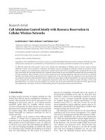
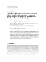
Figure 1: Code blocking and reassignment in an OVSF code tree. The filled circle and the crossed circle indicate the assigned and blocked
codes, respectively. A free code is indicated by an empty circle. When code C(3, 0) is assigned, it blocks the assignment of its all ancestors
and descendants, though its descendants are not shown in this figure. To lift the blocking on C(2, 0), code C(3, 0) can be freed by assigning
C(3, 2) to the call of C(3, 0).
codes of the same spreading factor to a mobile station in
order to achieve variable data rates. MC-CDMA requires
multiple transceivers to support variable data rates. OVSF-
CDMA reduces the hardware complexity of the mobile
station because it requires only a single transceiver to support
variable data rates. However, OVSF-CDMA suffers from the
code blocking problem, as explained next.
OVSF codes are generated recursively in a tree fashion,
asshowninFigure1, using Walsh matrices or applying
the following rule recursively: code C(m, k)oflevelm
generates the following two orthogonal codes of level m +1:
C(m +1,2k)
= [C(m, k), C(m, k)] and C(m +1,2k +1) =
[C(m, k), −C(m, k)], where −C(m, k) denotes the binary
complement of C(m, k), m is the level of the code in the
OVSF code tree and k istheindexofthecodeatlevelm,
assuming that the root code is at level zero [4, 6]. Any two
OVSF codes are orthogonal if and only if one of the two codes
is not the ancestor code of the other. For example, in Figure 1
codes C(2,0) and C(3, 0) are not orthogonal because C(2,0)
is an ancestor code of C(3, 0) and therefore they should not
be assigned to two different calls at the same time. When a
call is initially admitted, it is assigned an OVSF code with
the requested rate by an initial code placement algorithm.
Code blocking occurs when there is no corresponding free
OVSF code for an incoming call, even though the system
has sufficient residual capacity to support it. For example, in
Figure 1,anewcallrequiringanSF
= 4 cannot be assigned a
code since there is no free code with SF
= 4. To mitigate code
blocking, an existing call may be reassigned a different OVSF
code. For instance, to lift the blocking on C(2, 0) by freeing
C(3, 0), the call of C(3,0) is reassigned with C(3, 2), as shown
in Figure 1.
Dynamic bandwidth allocation in WCDMA networks
involves dynamic assignment of OVSF codes. When dynamic
bandwidth allocation is not used, code reassignments are
needed to eliminate code blocking only. When dynamic
bandwidth allocation is used, code reassignments are needed
to dynamically change the data rates assigned to mobile
stations as well. The computational overhead can be reduced
if the dynamic bandwidth allocation algorithm can easily
determine the code to be reassigned for supporting a higher
data rate. The control signaling overhead is reduced if
fewer number of bits are used to inform the mobile station
about the reassigned code. To reduce the code reassignment
overhead for a given code, this paper introduces the concept
of x-hop affinity-mate to find easily another code with the
same or higher rate.
This paper presents a class-based fair code allocation
(CFCA) protocol to support fairness, rate and delay guaran-
tees while allocating codes with low reassignment overhead
in WCDMA. CFCA includes three algorithms: class-based
code placement (CBP), class-based code replacement (CBR),
and dynamic bandwidth allocation (DBA). Algorithm 1 aims
to assign each flow a code whose affinity-mate codes can be
easily assigned later to the flow in case of stringent delay
requirements or poor channel conditions. If the affinity-mate
codes of a code are not available, then Algorithm 2 is invoked
to assign an appropriate code to the flow that requires
a higher-rate code due to poor channel conditions. Both
CBP and CBR also undertake reducing the number of code
EURASIP Journal on Wireless Communications and Networking 3
Input: A new call is admitted to the network because there exists at least one free code to support
the requested data rate. Variable max
hops denotes the maximum x in x-hop affinity-mate.
Output: The new call is assigned a free code with the highest weight W
i,j
.
begin
(1) Let r denote the number of those free OVSF codes whose SF equals s. Label them 1 to r from
left to right.
(2) for i
= 1tomax hops do
(3) for j
= 1tor do
(4) if (new call is RT (conversational or streaming)) then
(5) if (i-hop affinity-mate of the free code j is blocked or being used by an RT call) then
(6) W
i,j
= x
1
(7) else if (i-hop affinity-mate of the free code j is blocked or being used only by NRT calls)
then
(8) W
i,j
= x
2
(9) else if (i-hop affinity-mate of the free code j is free) then
(10) W
i,j
= x
3
(11) endif
(12) else if (new call is NRT (interactive or background)) then
(13) if (i-hop affinity-mate of the free code j is blocked or being used only by NRT calls) then
(14) W
i,j
= x
1
(15) else if (i-hop affinity-mate of the free code j is blocked or being used by an RT call) then
(16) W
i,j
= x
2
(17) else if (i-hop affinity-mate of the free code j is free) then
(18) W
i,j
= x
3
(19) endif
(20) endif
(21) endfor
(22) endfor
(23) The new call is assigned the free code with the highest weight W
i,j
among the r free codes
considered at the previous step. If there is more than one code with the highest weight, then
choose the code whose index i is the smallest to break the tie. Any further ties are broken
randomly.
end
Algorithm 1: Algorithm CBP.
reassignments while eliminating code blocking. Although
the existing bandwidth allocation algorithms address rate
allocation only without considering code placements and
reassignments, Algorithm DBA (see Algorithm 3)enables
rate allocation, code allocation and reassignment to interact
with each other in order to provide fairness, delay and rate
guarantees with low code reassignment overhead.
This paper also introduces a new performance metric,
called class-based rate degradation (CRD), to schedule
the code assignments of flows based on their current rate
degradation and traffic class. CRD helps meet the delay and
rate guarantees for real-time flows and to provide fairness for
non-real-time flows. Hence, the main contributions of this
paper are fourfold: (i) the code placement algorithm CBP for
reducing the overhead significantly for dynamic bandwidth
allocation in WCDMA networks, (ii) the code reassignment
algorithm CBR for freeing blocked codes if a cellular network
has sufficient residual capacity, (iii) the dynamic bandwidth
allocation algorithm DBA that uses the proposed CRD
metric to provide delay and rate guarantees for real-time
traffic, and fair access for non-real-time traffic, and (iv) the
concept of x-hop affinity-mate for reducing overhead in code
reassignments during dynamic bandwidth allocation.
While WCDMA-based cellular networks use OVSF codes
for channel allocation, variable spreading factor orthogonal
frequency code division multiplexing (VSF-OFCDM) has
been proposed as the transmission scheme for 4G next-
generation cellular networks [7–9]. In VSF-OFCDM, spread-
ing is done both in the time and in the frequency domains.
The amount of time and frequency domain spreading can be
adapted dynamically based on the data rate requirements and
channel conditions of the user. OVSF codes can be used to
determine the time domain and frequency domain spreading
in VSF-OFCDM systems [10, 11]. The amount of time
domain spreading can be varied by varying the allocated time
domain OVSF code. This is in turn modifies the amount of
frequency domain spreading, which is the number of orthog-
onal subcarriers used for frequency division multiplexing.
Frequency domain spreading gives better BER performance
when the number of users using the same time domain
code is low. However, when the number of users using the
same time domain code increases, intercode interference
increases. In order to reduce the intercode interference, users
are assigned a descendant code of the previous time domain
code of higher spreading factor as the new time domain
code. This reduces the number of users using the same time
4 EURASIP Journal on Wireless Communications and Networking
Input: A new call or an existing call that requires a higher-rate code requests a code of SF s.Butthe
network does not have a free code of SF s, even though the network has residual capacity to support
the call.
Output: An OVSF code of the required SF is freed by reassignment.
Begin
(1) if anewcallthen
(2) Let r denote the number of those blocked codes whose SF equals s, and label them from 1 to r.
(3) Among the r codes determine the codes that have the maximum weight W
i,l
for values of i = 1
to max
hops and l = 1tor.
(4) Determine the code j that has the least number of busy descendant codes assigned to real-time
calls among the codes with the same maximum weight. Any further ties are broken randomly.
(5) else if a real-time call requires code reassignment to meet its delay requirements then
(6) Let r denote the number of those codes whose SF equals s. Label them from 1 to r.
(7) Determine the code j that has the least number of busy descendant codes assigned to real-time
calls. Any further ties are broken randomly.
(8) else if a non-real-time call requires code reassignment to receive fair share of bandwidth then
(9) Let r denote the number of those codes of SF
= s that are free or assigned or blocked by
non-real-time calls. If a code of SF
= s is not available, search for a free code of the nearest
higher spreading factor.
(10) Determine the code j that is assigned to a non-real-time call with the minimum CRD value. Any
further ties are broken randomly.
(11) endif
(12) Let q denote the number of calls that are already assigned t descendants codes of code j.
(13) For each call 1 to q, assign a code using the CBP algorithm, if there are more than one code of
the required SF s
q
for the call. If no code is available of the required SF, then call CBR again to
free a code of the required SF s
q
.
(14) Assign code j to the new call or to the existing real-time or non-real-time call requesting code
reassignments.
end
Algorithm 2: Algorithm CBR.
domain code at least by half and thus reduces the intercode
interference. In this paper, we present how the presented
fair code allocation scheme can be used in 4G VSF-OFCDM
systems to pick an OVSF code that offers flexibility in time
and frequency domain spreading.
The rest of the paper is organized as follows. Section 2
presents the related work. Section 3 describes the system
model. Section 4 presents the CFCA protocol, including
the algorithms CBP, CBR, and DBA, along with the CRD
metric, and the concept of x-hop affinity-mate. Section 5
presents how the CFCA protocol can be used in VSF-
OFCDM systems. Section 6 presents a performance analysis
of the CFCA protocol. Simulation results are discussed in
Section 7, and the concluding remarks are made in Section 8.
2. Related Work
Code placement schemes [2, 12–25] assign codes to new
and handoff calls in such a way that the probability of call
blocking is reduced when code reassignments are not allowed
in the system. When code reassignments are allowed in the
system, the objective of code replacement schemes [26, 27]
is to reduce the number of code reassignments by freeing
blocked codes. Existing code placement and replacement
algorithms do not consider the impact of the code placement
on dynamic bandwidth allocation. They focus only on
keeping the code tree as compact as possible so that the
number of reassignments that could be needed when a new
callarrivesisreduced.Thisisnotsufficient, however, for
dynamic bandwidth allocation in which the codes of the
existing flows may need to be changed because of their poor
channel conditions and delay requirements. Therefore, our
code placement (CBP) and code reassignment (CBR) algo-
rithms allocate codes to flows by considering the possibility
of assigning higher rate codes to the flows when channel
conditions are poor or the flows have difficulties in meeting
their delay requirements. That is, when CBP or CBR assigns
a code to a flow, it ensures that the flow could be reassigned
a higher-rate code with a low cost of signaling overhead.
Dynamic bandwidth allocation to support the QoS and
fairness in WCDMA wireless cellular networks is studied
in [3, 28–34]. Most of the existing bandwidth allocation
algorithms ignore the signaling overhead in dynamic band-
width allocation. In [3, 34], some methods for reducing
the signaling overhead are discussed, though the methods
in [3] consider the multicode model. In addition, only
bursty trafficisconsideredin[34]. But, when real-time
traffic is continuous and non-real-time trafficisbursty,
an idle non-real-time flow can accumulate credits and
subsequently can receive a higher priority in scheduling.
This can affect adversely the rate allocated to continuous
real-time traffic, which may result in higher delay for real-
time packets. However, this paper considers fairness and QoS
EURASIP Journal on Wireless Communications and Networking 5
Input: A WCDMA-based cellular network with limited number of OVSF codes. Every admitted
flow (or call) f
i
is initially assigned an OVSF code, denoted C
i
(m, k), and the code C
i
(m, k)is
marked “assigned”. w
i
is given for every flow f
i
,andv is common for all flows. count is initially
set to zero.
Output: OVSF codes are assigned to all flows based on their delay and average data rate requirements,
while reducing signaling overhead.
begin
(1) for every frame do
(2) For those flows that have terminated, mark their codes “unassigned”.
(3) Assign every flow f
i
its initial code C
i
(m, k)evenif f
i
was assigned a different code during
the transmission of its last frame.
(4) count
← count +1;foreachflowf
i
,computeCRD
i
if (count mod w
i
) = 0.
(5) for j
= 0to3do
(6) if j is 0 then
(7) class
← “conversational”.
(8) else if j is 1 then
(9) class
← “streaming”.
(10) else if j is 2 then
(11) class
← “interactive”.
(12) else if j is 3 then
(13) class
← “background”.
(14) Let z equal the number of all those flows of class
type.
(15) while 0
≤ j ≤ 1andz>0 do
(16) Let f
i
denote the class flow with the highest CRD value among those class flows that are
not considered yet in this frame.
(17) if (CRD
i
> 0 then
(18) Call ASSIGN
HRC(i,CRD
i
, C
i
(m, k)).
(19) else
(20) Use the same code C
i
(m, k)offlow f
i
in this frame as well.
(21) endif
(22) z
← z − 1
(23) endwhile
(24) while 2
≤ j ≤ 3andz>0 do
(25) Let f
i
denote the class flow with the highest CRD value among those class flows that
are not considered yet in this frame.
(26) if (CRD
i
> 0) and (Code C
i
(m, k)offlowf
i
are not available due to its assignment to a
real-time flow then
(27) Call ASSIGN
HRC (i,CRD
i
, C
i
(m, k)).
(28) else
(29) Use the same code C
i
(m, k)offlow f
i
in this frame as well if it is available. Otherwise
no code is assigned to flow f
i
for this frame.
(30) endif
(31) z
← z − 1
(32) endwhile
(33) endfor
(34) endfor
end
Algorithm 3: Algorithm DBA.
guarantees for admitted calls of both continuous and bursty
real-time and non-real-time traffic. In [33], a joint power
and rate adaptation scheme is presented to meet the QoS
requirements of traffic belonging to various traffic classes.
In [30], a credit-based bandwidth allocation scheme to
ensure fairness and minimum rate guarantees under varying
channel conditions is presented. In [31], a threshold-based
scheme is described to dynamically change the code assigned
to a call so that the delay performance of the high QoS
trafficisimproved.In[32], a packet scheduling scheme for
continuously backlogged traffic is presented. However, in
[28, 30–33], only a general bandwidth allocation problem is
addressed without addressing code allocation and signaling
overhead during dynamic bandwidth allocation. Signaling
overhead is the number of bits of control information
required to inform the receivers of the mobile stations about
the OVSF codes assigned to them during dynamic bandwidth
allocation.
In [12–15], the authors address the code assignment
and reassignment problem so that the overhead of code
6 EURASIP Journal on Wireless Communications and Networking
reassignments is reduced while admitting a new or a hand-
off call.However,theydonotconsidertheimpactof
code placement and replacement on dynamic bandwidth
allocation. Dynamic bandwidth allocation addresses the
code assignment problem every time slot for existing calls
so that their delay and rate requirements are met, as
described in [3, 28, 34]. Hence, no existing work addresses
code placement and replacement together with dynamic
bandwidth allocation for OVSF-CDMA-based systems. In
addition, in 3G networks, the assignment of bandwidth (or
code) and power to a non-real-time flow would affect and
constrain the power and bandwidth that can be assigned
to a real-time flow during dynamic bandwidth allocation.
As stated in [34, 35], although non-real-time flows do not
have a strict delay bound, it is not desirable either to have
too long service times for them. Service providers should
provide “enough” bandwidth for all users, leading to more
subscribers it can serve, and more revenue they can earn.
Therefore, it is necessary to consider the scheduling of non-
real-time traffic along with real-time traffic so that non-real-
time flows do not get starved for extended periods of time.
This paper proposes the CFCA protocol to address all these
issues together in WCDMA networks.
3. System Model
We co nsider n flows (or calls), f
1
, f
2
, , f
n
,withinasingle
cell of a WCDMA-based cellular network, where the terms
“flow” and “call” are used interchangeably to mean a stream
of packets. Any call that is admitted into the system is referred
to as a new call regardless of whether it is a hand-off call
or is initiated in the current cell. The flows transmit data
through wireless channels separated by OVSF codes. Each
downlink channel is time slotted such that each time slot is
equal to a 10-millisecond WCDMA frame. Control signals
such as the transmit power control and rate information are
time-multiplexed with the user data in each time slot. We use
the control header to transmit the identity of the assigned
OVSF code. The code allocations and reassignments are done
by a dynamic bandwidth scheduler, based on the power and
code resources, the number of traffic flows, and the feedback
about the quality of the channels.
We are interested in the downlink control of transmis-
sions in such a way that the flows meet fairly the delay
and rate requirements. To achieve this, the rate allocated
to a mobile station is dynamically varied by adjusting the
spreading factor of the assigned OVSF code [36]. To ensure
successful reception of the packetized data at a mobile station
(MS), there is a limit on the achieved bit error rate (BER).
Depending on the spreading factor, modulation and coding
scheme used, a target E
b
/I
o
should be achieved at the MS so
that the limit on BER is not exceeded. E
b
/I
o
represents the
ratio of energy-per-bit (E
b
) to interference power spectral
density (I
o
). Based on the channel state feedback received
from the MS and the spreading factor used, the BS adjusts
the power, modulation and coding used for a flow to meet
the target E
b
/I
o
. But, in order not to introduce any additional
intercell interference to other cells, the total power at the BS
is constrained. As a result, the power requirements of all the
flows may not be met at some instances. In this case, flows
are served in their priority order as long as the total transmit
power constraint of the BS is not violated.
The third generation (3G) universal mobile telecommu-
nications system (UMTS) describes four traffictypes(or
QoS classes), namely, conversational (e.g., voice), streaming
(e.g., streaming video), interactive (e.g., web browsing) and
background (e.g., email). In the proposed code placement
and replacement algorithms, the conversational and stream-
ing classes are referred to as the real-time (RT) class and
interactive and background classes are referred to as the non-
real-time (NRT) class. The four traffic classes of WCDMA
are distinguished by the proposed dynamic bandwidth
allocation algorithm according to their priorities; that is,
conversational traffic is considered first, then streaming,
followed by interactive and background traffic classes.
For simplicity, we assume a two-state channel model,
according to which the channel can be either in normal state
or poor state. Under normal channel conditions, the flow
can achieve a data rate equal to its average requested data
rate using the OVSF code assigned to it at admission. Under
poor channel conditions, a flow still receives data with the
same power of transmission, but at a lower rate because of
the use of a lower modulation level and lower coding rate. To
achieve the average data rate, we assign a higher rate (lower
SF) code for real-time flows under poor channel conditions.
Asshownin[37], for higher spreading factors (SF
≥ 32),
the additional power needed to achieve the same BER while
moving from SF
= s to SF = s/2isoftheorderof0.5dB.The
admission control scheme presented in Section 4 ensures that
this additional power is always available for all admitted real-
time flows under poor channel conditions. It should be noted
that the additional power needed to achieve the same BER
without changing the SF, modulation and coding scheme is
relatively high and is of the order of 3 dB as shown in [38].
We use a simp lified E
b
/I
o
modelasthechannelmodel.
In a WCDMA network, the E
b
/I
o
achieved at the mobile k is
expressed as
E
b
I
o
k,SF
k
,MCS
k
=
W
R
k,t
P
j
k,t
L
j
k,t
(
1
− α
)
×
P
T,t
− P
j
k,t
×
L
j
k,t
+ N
o
+ I
inter,k,t
,
(1)
E
b
I
o
k,SF
k
,MCS
k
= SF
k,t
P
j
k,t
L
j
k,t
(
1
− α
)
×
P
T,t
− P
j
k,t
×
L
j
k,t
+ N
o
+ I
inter,k,t
,
(2)
where (E
b
/I
o
)
k,SF
k
,MCS
k
is the E
b
/I
o
requirement of kth
flow assuming a spreading factor of SF
k
and modulation
and coding scheme MCS
k
, P
j
k,t
is the instantaneous power
allocated to flow f
k
by base station j at time t, R
k,t
is the
EURASIP Journal on Wireless Communications and Networking 7
instantaneous data rate allocated to flow f
k
at time t, L
j
k,t
is
the power loss on the path from base station j to mobile k
at time t, P
T
is the total power budget of the base station on
the downlink, P
T,t
is the instantaneous transmit power of the
base station on the downlink for all existing flows at time t,
N
o
is the noise power spectral density, I
inter,k,t
is the intercell
interference at mobile k at time t, W is the chip rate, α is the
own-cell orthogonality factor (typically ranges between 0.4
and 0.9), and SF
k,t
is the spreading factor of the code assigned
to flow k at time t. L
j
k,t
is the product of distance-based path
loss, slow fading (shadowing), and fast fading (multipath) on
the wireless channel from BS j to MS k. Path loss PL
j
k,t
is
computed as a function of distance D
j
k,t
asgivenin(4), where
δ is the path loss exponent. Slow fading, S
j
k,t
is considered to
be log-normally distributed around the distance-based path
loss PL
j
k,t
with zero mean and standard deviation. Fast fading,
F
j
k,t
is generated using a Rayleigh fading distribution with
zero mean and standard deviation. Hence, L
j
k,t
and PL
j
k,t
can
be written as
L
j
k,t
= PL
j
k,t
× S
j
k,t
× F
j
k,t
,
(3)
PL
j
k,t
=
D
j
k,t
−δ
.
(4)
4. Class-Based Fair Code Allocation
(CFCA) Protocol
This section presents our class-based fair code allocation
(CFCA) protocol to assign the appropriate OVSF codes to the
traffic flows based on their delay and data rate requirements,
channel conditions, and fairness. The objectives of the CFCA
are as follows: (i) to assign bandwidth fairly to real-time
flows so that their rate and delay requirements are met, (ii)
to assign fairly the residual bandwidth among non-real-time
flows, and (iii) to reduce the overhead for code reassignments
in dynamic bandwidth allocation. CFCA uses three main
algorithms, and the list of notations used by these algorithms
is shown in Table 1.
CFCA admits a new real-time call to the network if the
total network capacity and base station power budget is
always capable of supporting all the existing real-time flows
under poor channel conditions at which they need higher
rate codes. Therefore, there is a constraint on the number of
admitted real-time flows to help meet the delay guarantees of
real-time flows in the presence of poor channel conditions.
It should be noted that a poor channel condition implies
a channel state at which a mobile station is still able to
receive data with the same power of transmission, but at a
lower rate because of the use of lower modulation level and
lower coding rate. The acceptable poor channel condition
at any location in a coverage area is determined by the
cellular service providers by considering path loss, fading,
and worst case inter- and intracell interference. Service
providers can then use the acceptable poor channel condition
as a constraint in determining the optimal locations of base
stations in a given coverage area. For example, in [39, 40],
the authors propose optimization models for base station
locations considering the signal-to-noise ratio as the quality
measure. In [41], the authors propose models for base station
location so that the quality of service constraints is satisfied.
Once a service provider plans his network for a given poor
channel condition, the aim of the CFCA protocol is to
provide QoS guarantees to those real-time flows that can at
least maintain this poor channel condition by just making
use of the power and code resources used to determine their
admission.
When a flow f
i
is admitted, there are two bandwidth
requirements for flow f
i
: B
n
( f
i
)andB
p
( f
i
). B
n
( f
i
)isthe
bandwidth needed for flow f
i
under normal channel con-
ditions, whereas B
p
( f
i
) is the bandwidth needed for flow
f
i
under poor channel conditions. B
n
( f
i
)representsthe
spreading factor (SF) required to meet at least the average
data rate offlow f
i
under normal channel conditions at which
a high-order modulation and coding scheme is used. B
p
( f
i
)
represents the spreading factor (SF) required to meet the
average data rate of flow f
i
under poor channel conditions
at which a lower-order modulation and coding scheme is
used. B
n
( f
i
) is greater than B
p
( f
i
) and, therefore, B
p
( f
i
)
requires a higher-rate code (code of lower SF) than the code
needed by B
n
( f
i
). The total bandwidth needed by all real-
time flows under poor channel conditions cannot exceed
the total network capacity. Thus, a new real-time call f
i
is
admitted if (5)holds:
1
B
p
f
1
+
1
B
p
f
2
+ ···+
1
B
p
f
i−1
+
1
B
p
f
i
≤
1,
(5)
where f
1
, f
2
, , f
i−1
are the existing real-time flows, and
B
p
( f
k
) is the SF required to meet the data rate of flow f
k
under poor channel conditions for 1 ≤ k ≤ i.Asforthe
non-real-time flows, CFCA admits a new non-real-time flow
if the total bandwidth requirements of all existing real-time
and non-real-time flows under normal channel conditions
are less than the total network capacity. Assuming that m
−
1 is the number of all existing flows (real-time and non-
real-time) in the network, a new non-real-time flow f
m
is
admitted if (6)holds:
1
B
n
f
1
+
1
B
n
f
2
+ ···+
1
B
n
f
m−1
+
1
B
n
f
m
≤
1,
(6)
where B
n
( f
k
) is the SF required to meet the data rate of flow
f
k
under normal channel conditions. This paper assumes
that a higher-level modulation and a higher-rate coding
scheme are used under normal channel conditions. When
channel conditions become poor, both modulation level and
coding rate are reduced [42]. For instance, under normal
channel conditions, let us assume that the modulation
level is 8 (64 QAM) and coding rate is 1/2. When the
channel conditions become poor, the modulation level can
be lowered to 4 (16 QAM) or 2 (QAM), while the coding rate
could be reduced from 1/2 to 1/3 to meet the required E
b
/I
o
.
To compensate for the loss in data rate under poor channel
conditions, we assign a higher rate code of lower SF that will
run with lower modulation level and coding rate. In [42], the
authors show how the achieved data rate can be modified by
changing the modulation and coding scheme.
8 EURASIP Journal on Wireless Communications and Networking
Table 1: Notations.
f
i
Flow i or call i
R
i,t
Instantaneous data rate of flow f
i
at time t
R
i,avg
Requested average data rate of flow f
i
SF
i,t
Spreading factor of the code assigned to flow f
i
at time t
C(m, k)
OVSF code at level m with index k
W
x,l
Weigh t of code I based on its x-hop affinity-mate of rate 2
x−1
× R
CRD
i,j
Class-based rate degradation ratio of flow f
i
at the end of time slot j
WRD
i,j
Window Rate Degradation of flow f
i
for window j
v
Number of time slots over which CRD is computed
w
i
Number of time slots for which flow f
i
can tolerate its data rate to be lower than average data rate; v
time slots contain one or more windows
w
i
(C), w
i
(S), w
i
(I),w
i
(B)
Window sizes of the conversational, streaming, interactive, and background traffic classes, respectively,
for flow f
i
CRD
th
CRD threshold for ensuring fairness in rate allocation to NRT flows
B
n
( f
i
)
The SF needed by flow f
i
to meet at least the average data rate under normal channel conditions
B
p
( f
i
)
The SF needed by flow f
i
to meet the average data rate under poor channel conditions
Therefore, to ensure the availability of a higher rate
code of lower SF for real-time flows under poor channel
conditions, the following equations should also hold before
admitting a new real-time flow. In these equations, we
consider only the power required to use a higher rate code
of spreading factor B
p
( f
k
) instead of the normal rate code
of spreading factor B
n
( f
k
). The additional power needed to
use a higher rate code is constant and depends only on the
amount of reduction in the SF and does not depend on the
channel conditions. Based on the analysis in [43], we can first
express (2)asaninequality:
SF
k,t
P
j
k,t
L
j
k,t
(
1
− α
)
×
P
T,t
− P
j
k,t
×
L
j
k,t
+ N
o
+ I
inter,k,t
≥
E
b
I
o
k,SF
k
,MCS
k
.
(7)
Since this equation is evaluated only at the time of admission
for each flow, we can eliminate t as a parameter and replace
P
T,t
with P
τ
to represent the sum of transmit power assigned
to all real-time flows at admission. Equation (7)impliesthat
P
j
k
≥
(
1
− α
)
× P
T
× L
j
k
+ N
o
+ I
inter,k
SF
k
/
(
E
b
/I
o
)
k,SF
k
,MCS
k
+
L
j
k
×
(
1
− α
)
,(8)
P
j
k,p
≥
(
1
− α
)
× P
T
× L
j
k
+ N
o
+ I
inter,k
B
p
f
k
/
(
E
b
/I
o
)
k,SF
k
,MCS
k
+
L
j
k
×
(
1
− α
)
,(9)
P
T
≥ P
τ
=
i
k=1
P
j
k,p
,
(10)
where P
j
k,p
is the power requirement of flow f
k
under poor
channel conditions when an SF of B
p
( f
k
) is used. Before the
base station admits a new real-time flow f
i
, the base station
first ensures that the sum of P
j
1,p
, P
j
2,p
, , P
j
(i
−1),p
of existing
real-time flows and P
j
i,p
of the new flow does not exceed P
T
shown in (10).
From (9)and(10), it follows that
P
T
≥ P
τ
=
i
k
=1
(
1
− α
)
× P
τ
× L
j
k
+ N
o
+ I
inter,k
i
k
=1
B
p
f
k
/
(
E
b
/I
o
)
k,SF
k
,MCS
k
+
L
j
k
×
(
1
− α
)
,
(11)
P
T
≥ P
τ
=
i
k
=1
N
o
+ I
inter,k
i
k
=1
B
p
f
k
/
(
E
b
/I
o
)
k,SF
k
,MCS
k
+
L
j
k
×
(
1
− α
)
⎛
⎝
1 −
i
k
=1
(
1
− α
)
× L
j
k
i
k
=1
B
p
f
k
/
(
E
b
/I
o
)
k,SF
k
,MCS
k
+
L
j
k
×
(
1
− α
)
⎞
⎠
.
(12)
Since P
τ
is a positive quantity, the following feasibility
constraint should be met:
i
k
=1
(
1
− α
)
× L
j
k
i
k
=1
B
p
f
k
/
(
E
b
/I
o
)
k,SF
k
,MCS
k
+
L
j
k
×
(
1
− α
)
< 1.
(13)
Areal-timeflowf
i
is admitted only if (5), (9), and (10)
together hold. Similarly, a new non-real-time flow f
m
is
EURASIP Journal on Wireless Communications and Networking 9
Table 2: Protocol CFCA.
Step 1
For a real-time call f
i
, determine B
n
( f
i
), the spreading factor required under normal channel conditions, and B
p
( f
i
), the
spreading factor required under poor channel conditions. Admit the real-time call if (5), (9), and (10)hold.Fora
non-real-time call, determine only B
n
( f
i
), the spreading factor required under normal channel conditions, and admit it if
(6), (14), and (15)hold.
Step 2
IfafreecodewiththespreadingfactorB
n
( f
i
) is available, go to next step. Otherwise, use Algorithm CBR to free a code
with spreading factor B
n
( f
i
) by doing code reassignments.
Step 3
Use Algorithm CBP to initially allocate a particular free code of spreading factor B
n
( f
i
) for the new call.
Step 4
Run Algorithm DBA to dynamically allocate codes for meeting delay and rate guarantees of all active calls.
admitted only if the following (14)and(15) hold along with
(6):
P
j
k,n
≥
(
1
− α
)
× P
γ
× L
j
k
+ N
o
+ I
inter,k
B
n
f
k
/
(
E
b
/I
o
)
k,SF
k
,MCS
k
+
L
j
k
×
(
1
− α
)
,
(14)
P
T
≥ P
γ
=
m
k=1
P
j
k,n
,
(15)
where f
1
, f
2
, , f
m−1
are the existing real-time and non-real-
time flows, B
n
( f
k
) is the SF required to meet the data rate of
flow f
k
under normal channel conditions for 1 ≤ k ≤ m, P
j
k,n
is the power requirement of flow f
k
under normal channel
conditions, and P
γ
is the sum of transmit power assigned to
all flows at admission.
CFCA is implemented in four steps as shown in Table 2.
In Step 1 of CFCA, the SF of a new call is determined.
A real-time call is admitted depending on whether (5),
(9), and (10) hold or not. Similarly, a non-real-time call is
admitted depending on whether (6), (14), and (15) hold or
not. It should be noted that the SF required under poor
channel conditions (B
p
( f
i
)) is only used to determine the
admissibility of a real-time call in Step 1 of the CFCA
protocol using (5). Once it has been determined that enough
code resources meet the rate requirements of a real-time call
even under poor channel conditions, only a code whose SF
is equal to that required under normal channel conditions
(B
n
( f
i
)) is assigned to a real-time call. During the life time
of a call, if the channel conditions become poor, then a
higher rate (of lower SF B
p
( f
i
)) code is assigned to meet
the delay requirements of a real-time call. In the second step
of CFCA, if a free code of the required spreading factor is
not available even though the system has enough capacity
to support the new call, algorithm CBR is invoked to free
a code of the required spreading factor. The code that is
made free is then assigned to the new call. In the third step,
when a new call arrives, it is assigned an OVSF code of the
required spreading factor using the CBP algorithm. In the
fourth step, the call can use its initial code that is assigned by
the CBP and CBR algorithms or a higher-rate code, and this
decision is made every time slot by the DBA algorithm. When
a higher-rate code is used, the mobile station is informed
about the higher-rate code using control channel signaling.
We use in-band control channel signaling mode [26], the
control header is decoded by the mobile station using the
initially assigned code. If the control header has control
information suggesting the use of a different higher-rate code
to decode the data segment, the data segment is decoded
using the higher rate code. In the next frame, the control
header is again decoded using the initially assigned code and
the process continues. The CFCA protocol uses the concept
of x-hop affinity-mate to keep the control channel signaling
overhead low when higher rate codes are assigned to calls.
Before presenting the algorithms CBP, CBR, and DBA, we
now introduce the definitions for CRD and x-hop affinity-
mate next. We consider the last v time slots of flow f
i
,
each of which corresponds to a frame transmission time.
We assume that w time slots constitute a window, so that v
time slots have v/w windows. Let R
i,rcv
denote the average
rate that flow f
i
receives over a window, while R
i,avg
denotes
the requested average rate. The value of R
i,rcv
depends on
the modulation and coding scheme used. For example, for
a symbol rate of 100 symbols per second, QPSK modulation
scheme (BPS
= 2) and 1/2 convolutional coding (CR = 1/2)
give an information bit rate of 100 bits per second. On the
other hand 64-QAM modulation scheme (BPS
= 6) and 3/4
turbo coding (CR
= 3/4) give an information bit rate of
450 bits.
Definition 1 (class-based rate degradation (CRD)). CRD
i
represents the average rate degradation for which flow f
i
experiences over the last v time slots consisting of v/w
windows during which it receives less rate than the requested
average data rate R
i,avg
.CRD
i
is expressed as
CRD
i
=
w
i
v
v/w
i
j=1
⎛
⎝
R
i,avg
− min
R
i,avg
,
w
i
k=1
R
i,(t−k−w
i
×(j−1))
/w
i
R
i,avg
⎞
⎠
.
(16)
CRD
i
(i.e., CRD of flow f
i
) basically refers to the ratio of
(R
i,avg
−R
i,rcv
)toR
i,avg
over v/w
i
windows, when R
i,avg
≥ R
i,rcv
.
The value of v is the same for all types of flows, whereas
the window size w
i
gets larger as the class priority of flows
decreases. The value of v depends on the minimum time
interval during which average rate requirements of non-real-
time flows must be met. On the other hand, w
i
is determined
based on the delay requirements of f
i
to indicate the number
of consecutive time slots that flow f
i
can tolerate its data
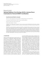
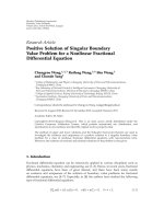
rate to be lower than average data rate. In Figure 2,the
value of v is chosen as 20 because it is the minimum time
interval during which the average rate requirement of the
10 EURASIP Journal on Wireless Communications and Networking
1234567891011121314151617181920
t (time slot)
R
i,rcv
= (2+1+1+1+1+1+0+0+2+2+2+3+3+3+3+3+3+3+3+3)/20
WRD
i,1
= 0
CRD
i,20
= [0]/1 = 0
NRT flow, w
= 20,v = 20, 1 window in 20 time slots
CRD
i,20
= [0.4+0.5+0.0+0.0]/4 = 0.225
RT Flow, w
= 5, v = 20, 4 windows in 20 time slots
Window 4 Window 3 Window 2 Window 1
R
i,avg
= 2
R
i,rcv
= (2+1+1+1+1)/5
WRD
i,4
= 0.4
R
i,avg
= 2
R
i,rcv
= (1+0+0+2+2)/5
WRD
i,3
= 0.5
R
i,avg
= 2
R
i,rcv
= (2+3+3+3+3)/5
WRD
i,2
= 0
R
i,avg
= 2
R
i,rcv
= (3+3+3+3+3)/5
WRD
i,1
= 0
R
i,avg
R
i,t
(data rate)
R
2R
3R
Figure 2: The data rates of a flow that are achieved within 20 time slots are the average data rate 2R in slot 1, the data rate R in slots 2 to 6,
no data transmission in slots 7 to 8, and the average rate 2R or more in slots 9 to 20. (a) If the flow is a real-time (RT) flow with a window
size of w
= 5overv = 20 time slots, then CRD
i,20
istheaverageofthewindowratedegradationsWRD
i,1
= 0.0, WRD
i,2
= 0.0, WRD
i,3
= 0.5,
and WRD
i,4
= 0.4. That is, CRD
i,20
is (0.4+0.5+0.0+0.0+0.0)/4 = 0.225. (b) If the flow is a non-real-time (NRT) flow with a window size
of w
= 20 over v = 20 time slots, then CRD equals zero.
non-real-time flow must be met. The v time slots consist of
v/w
i
distinct windows, each having w
i
time slots. CRD
i
is
computed as follows: (a) for each window j from j
= 1to
v/w
i
, compute the average R
i,rcv
for all rates R
i,(t−k−w
i
∗(j−1))
over w
i
time slots, where R
i,(t−k−w
i
∗(j−1))
refers to the received
data rate at time slot (t
− k − w
i
∗ (j − 1)), (b) determine
the minimum of R
i,avg
and R
i,rcv
to find out whether R
i,rcv
is below the requested average rate R
i,avg
, (c) compute the
window rate degradation, denoted by WRD
i,j
,forwindow
j by subtracting the minimum of R
i,avg
and R
i,rcv
from R
i,avg
and then by dividing the resultant by R
i,avg
(i.e., WRD
i,j
=
(R
i,avg
− min(R
i,avg
, R
i,rcv
))/R
i,avg
), and (d) finally find the
average of all v/w
i
windows’ degradations and then call
it CRD
i
.Atagiventimeslot,CRD
i
is determined based
on the received rates of the flow at the last v time slots.
The window sizes of all the flows in a trafficclassarethe
same, and depend on the priority of their trafficclassin
the sense that a higher priority traffic class has a lower-size
window. That is, if w
i
(C), w
i
(S), w
i
(I), and w
i
(B)denotethe
window sizes of the conversational, streaming, interactive,
and background traffic classes, respectively, then it follows
that: w
i
(C) <w
i
(S) <w
i
(I) <w
i
(B). Figure 2 shows how
CRD
i
is computed. Note that CRD
i
is computed by (16)ina
sliding window manner with a period of w
i
time slots. This
implies that, for flow f
i
,CRD
i
is computed after every w
i
time
slot. CRD is somewhat similar to Degradation Ratio (DR) in
[44] that determines whether a new call can be admitted by
degrading the rates of existing flows.
This paper uses CRD to support delay requirements of
real-time traffic by ensuring that the average requested rate
is met at variable window sizes of frames. That is, if a flow
is more delay sensitive, then the window size during which
the requested average rate should be met is made smaller
in the computation of CRD. In order to determine whether
a flow meets the delay and rate requirements, we employ
CRD for all flows and traffic types as described earlier. The
value of CRD
i
for flow f
i
ranges from 0 to 1 to indicate
“no degradation” and “maximum degradation”, respectively.
Specifically, if CRD
i
equals zero, then flow f
i
meets its both
delay and rate requirements. However, if CRD
i
is greater than
zero, it indicates that flow f
i
has experienced a degradation in
rate and delay requirements, and the CRD
i
value represents
the amount of degradation. In [44] the objective of the
degradation metric is to intentionally degrade the QoS of
existing flows in order to admit new flows. However, the
objective of this paper is to support the rate and delay
guarantees by keeping the degradations at a low value.
The authors in [3, 34] present scheduling algorithms
to dynamically assign OVSF codes to mobile users on a
timeslot-by-timeslot basis based on a credit-based mecha-
nism. A credit-based mechanism assigns credits to a flow
every time slot based on its requested average rate and deletes
credits from a flow every time slot based on the rate allocated
to that flow. Flows with higher credits have higher priority
in scheduling and code allocation. The algorithms provide
average data rate guarantee for bursty data traffic. Though
the algorithms can be used for real-time traffic, it is more
appropriate for non-real-time traffic because of the following
issue. When there exist more than one flow with the same
traffic type, these flows are scheduled based on their CRD
values such that the flow with the highest CRD value is
scheduled first to prevent it from having further degradation.
EURASIP Journal on Wireless Communications and Networking 11
Table 3: The x-hop affinity-mates and data rates of some codes shown in Figure 1,for1≤ x ≤ 3, where R represents the data rate of any
code with SF
= 8. The affinity-mates of any other code can be determined similarly. This table is stored at the base station for determining
the affinity-mate codes faster.
Code 1-hop affinity-mates 2-hop affinity-mates 3-hop affinity-mates
[C(3, 0), R][C(2, 0), 2R], [C(3, 1), R][C(2, 1),2R], [C(3, 2),C(3, 3),R][C(2, 2), C(2, 3),2R], [C(3, 4),C(3, 5),C(3, 6),C(3, 7),R]
[C(3, 1), R][C(2, 0), 2R], [C(3, 0), R][C(2, 1),2R], [C(3, 2),C(3, 3),R][C(2, 2), C(2, 3),2R], [C(3, 4),C(3, 5),C(3, 6),C(3, 7),R]
[C(3, 2), R][C(2, 1), 2R], [C(3, 3), R][C(2, 0),2R], [C(3, 0),C(3, 1),R][
C(2, 2), C(2, 3),2R], [C(3, 4),C(3, 5),C(3, 6),C(3, 7),R]
[C(3, 3), R][C(2, 1), 2R], [C(3, 2), R][C(2, 0),2R], [C(3, 0),C(3, 1),R][C(2, 2), C(2, 3),2R], [C(3, 4),C(3, 5),C(3, 6),C(3, 7),R]
[C(2, 0), 2R][C(2, 1), 2R][C(2, 2), C(2, 3),2R]—
[C(2, 1), 2R][C(2, 0), 2R][C(2, 2), C(2, 3),2R]—
In addition, to help reduce the degradation of a flow with
high CRD value, our algorithm DBA attempts to increase
the data rate of the flow above the requested average rate to
meet the delay requirements. Increasing the rate requires the
assignment of ahigher rate code. The CFCA protocol uses the
concept of x-hop affinity-mate whose definition is presented
next, to keep the overhead during the assignment of higher-
rate code low.
Definition 2 (x-hop affinity-mate). Two OVSF codes are
referred to as x-hop affinity-mates if one of the following two
conditions holds: (i) their nearest ancestor has the distance of
exactly x hops to one of them and the distance of at most x
hops to the other one, or (ii) one of the codes is the ancestor
of the other one and the distance between them equals x
hops, where a hop corresponds to an edge in the OVSF code
tree.
The first part of the definition basically says that two
codes are x-hop affinity-mates only if none of the two codes is
at a distance greater than x hops from their common ancestor
and at least one of the two codes is at a distance of x hops
from their common ancestor. Table 3 shows a table for the
1-hop, 2-hop, and 3-hop affinity-mates of all the codes in
the code tree illustrated in Figure 1. Because the lowest SF in
WCDMA is 4, the codes C(0, 0), C(1,0), and C(1, 1) are not
included in the table. In determining the code to be assigned
to a new call, the CBP algorithm in Step 3 of the CFCA
protocol chooses the code that has the best x-hop affinity-
mate of 2
x−1
times higher rate. If more than one free code
with the best 1-hop affinity-mate is available, CBP attempts
to find a code with the best 2-hop affinity-mate and so on
until x-hops. The determination of the best x-hop affinity-
mate is explained in the next section.
4.1. Class-Based Code Placement (CBP) Algorithm. When a
new call arrives, there may be more than one free code that
could be assigned to the call. To choose the free code that
can cause the minimal overhead of code reassignments in
case of poor channel conditions, we introduce the concept
of weight for free codes as follows. For a new call of traffic
type u,afreecodej with SF
= s and rate R,anditsi-hop
affinity-mate code with the data rate of 2
i−1
× R, the weight
W
i,j
of the code j is determined by a number x
k
depending
on the traffictypeu and the status (e.g., free, busy with a
real-time call, or busy with a non-real-time call) of the i-hop
affinity-mate code, for 1
≤ k ≤ 3and0<x
1
<x
2
<x
3
.
When the new call is a real-time call, the most desirable
free code is the one whose i-hop affinity-mate code is free
(lines 9-10), so that the call may be reassigned easily the
free affinity-mate code of higher rate to meet its delay and
rate requirements. The second most desirable free code is the
one whose affinity-mate code is currently being used by a
non-real-time call (lines 7-8) because the real-time call may
be assigned the affinity-mate of higher rate that is currently
being used by a non-real-time call when the real-time call
requires a higher data rate. When the new call is a non-real-
time call, the most desirable free code is again the one whose
affinity-mate code is free (lines 17-18) because the call may
beassignedthehigherrateaffinity-mate to increase its rate.
But, the second most desirable free code is the one whose
affinity-mate code is currently being used by a real-time call
(lines 15-16) because the real-time call can use the codes
assigned to this non-real-time call to improve its rate. If there
are more than one free code with the same highest weight, the
code with the smallest index i is chosen. Any further ties are
broken randomly.
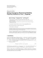
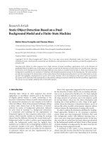
Example 1. In Figure 3(a),anOVSFcodesubtreeisshown
such that the code C(0, 0) refers to an OVSF code with SF
=
X and the data rate of 8R,for4≤ X ≤ 64. Let x
1
= 1,
x
2
= 2, and x
3
= 3. The OVSF code subtree is assumed to
have initially a single RT call, namely, Call 1, that is assigned
code C(3, 0). When a new NRT call, namely, Call 2, requiring
acodewithSF
= 4 is admitted to the network, there are
three free codes with SF
= 4: C(2,1), C(2, 2), and C(2, 3).
Algorithm CBP determines the weights W
1,j
(lines 12–20)
of the three free codes as 2, 3, and 3, respectively. Because
the free codes C(2, 2) and C(2, 3) have the same weight W
1,j
,
we need to determine their W
2,j
values to try to choose a
code with a higher weight. But, their W
2,j
values happen
to be the same as well and, therefore, CBP chooses C(2, 3)
randomly to break the tie (line 23). Now, a new RT call (Call
3) requiring an SF
= 8isadmittedtothenetwork.Thereare
fivefreecodes,C(3, 1) to C(3, 5). Algorithm CBP determines
the weights W
1,j
(lines 4–11) of the five free codes as 1, 3,
3, 3, and 3, respectively. CBP computes the W
2,j
values of
codes C(3, 2) to C(3,5)as1,1,2,and2,respectively,and
then chooses one of C(3,4) and C(3,5) randomly (line 23).
A new RT call (Call 4) requiring an SF
= 4 is assigned code
C(2, 1) as it is the only code available with that SF. Now,
a new RT call (Call 5) is assigned code C(3, 5) since it has
12 EURASIP Journal on Wireless Communications and Networking
C(3, 0)
[Call 1, RT] [Call 3, RT] [Call 5, RT]
[Call 4, RT] [Call 2, NRT]
C(3, 1) C(3, 2)
C(2, 1)
C(0, 0)
C(2, 2) C(2, 3)
C(3, 3) C(3, 4) C(3, 5) C(3, 6) C(3, 7)
C(2, 0)
C(1, 0) C(1, 1)
SF
= X,8R
SF
= 2X,4R
SF
= 4X,2R
SF
= 8X, R
(a)
C(3, 0)
[Call 1, RT] [Call 3, RT] [Call 5, RT]
[Call 4, RT] [Call 2, NRT]
C(3, 1) C(3, 2)
C(2, 1)
C(0, 0)
C(2, 2) C(2, 3)
C(3, 3) C(3, 4) C(3, 5) C(3, 6) C(3, 7)
C(2, 0)
C(1, 0) C(1, 1)
SF
= X,8R
SF
= 2X,4R
SF
= 4X,2R
SF
= 8X, R
(b)
Figure 3: An example for showing the operation of Algorithm CBP over an OVSF code subtree, where the code C(0, 0) refers to an OVSF
code with SF
= X and the data rate of 8R,for4≤ X ≤ 64. Let x
1
= 1, x
2
= 2, and x
3
= 3. (a) The OVSF code subtree is assumed to
have initially a single real-time (RT) call, namely, Call 1, that is assigned code C(3, 0). When a new non-real-time (NRT) call, namely, Call 2,
requiring a code with SF
= 4 is admitted to the network, there are three free codes with SF = 4: C(2, 1), C(2, 2), and C(2, 3). Algorithm CBP
determines the weights W
1,j
(lines 12–20) of the three free codes as 2, 3, and 3, respectively. Because the free codes C(2, 2) and C(2, 3) have
thesameweightW
1,j
, we need to determine their W
2,j
values to try to choose a code with a higher weight. But, their W
2,j
values happen to
be the same as well and, therefore, CBP chooses C(2, 3) randomly to break the tie (line 23). The initial assignments of codes to calls 3, 4, and
5 are done similarly. (b) When calls 1 and 5 experience poor channel conditions during dynamic bandwidth allocation, they are assigned the
higher rate codes C(2, 0), and C(2, 3), respectively, to compensate the data rate decline due to deteriorating channel conditions.
ahigherW
2,j
over the code C(3,1) (note that C(3, 5) and
C(3,1)havethesamevalueofW
1,j
). Figure 3(b) illustrates
how dynamic code allocation can be implemented when Call
1 and Call 5 experience poor channel conditions. In this case,
Call 1 and Call 5 are assigned the higher rate codes C(2, 0)
and C(2,3), respectively, to compensate the data rate decline
due to deteriorating channel conditions.
4.2. Class-Based Code Reassignment (CBR) Algorithm. The
objective of the CBR algorithm is to find and free the
most desirable code (as mentioned in Section 4.1), when a
new or existing call needs code reassignments. To achieve
this, the CBR algorithm performs reassignments under three
cases, namely, to assign code to a new call, a real-time call
requesting a higher-rate code, and a non-real-time call to
ensure fairness. Lines 1 to 4 handle the first case, where a new
call requiring an SF of s requires code reassignments because
of code blocking. On line 2, all blocked codes of required
SF s arefound.Online3,thealgorithmfirstfindsallthe
codes of SF s that have the maximum weight W
i,l
as defined
in the CBP algorithm. On line 4, the algorithm then finds
the code j that has the least number of descendant codes
that are assigned to real-time calls. This leads the number
of reassignments to be low for real-time calls. Lines 5 to 7
handle the second case, where a code for reassignment is
chosen when a real-time call needs to increase its data rate
and when none of its x-hop affinity-mate is available. In this
case, a code that is assigned or blocked by only non-real-time
calls is reassigned so that the other real-time calls are not
affected by this reassignment. If there are more than one code
available for reassignment, code j that has the least number
of descendant codes that are assigned to real-time calls is
chosen for reassignment. Lines 8 to 10 handle the third case,
where code reassignments are performed to ensure fairness
in bandwidth allocation for non-real-time calls. In this case,
a non-real-time call with a high CRD value is assigned the
code of a non-real-time call with a low CRD value. The
busy descendant codes of code j are then freed by doing
code reassignments on lines 12-13, and finally the code j is
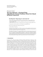
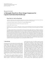
assigned to the incoming call on line 14. Figure 4 shows an
example for the operation of Algorithm CBR.
4.3. Dynamic Bandwidth Allocation (DBA) Algorithm. Before
describing the algorithm DBA, we first explain the CRD
EURASIP Journal on Wireless Communications and Networking 13
C(3, 0)
NRT
C(3, 1)
C(3, 2)
C(2, 1)
C(0, 0)
C(2, 2) C(2, 3)
C(3, 3)
NRT
(i)
C(3, 4) C(3, 5)
RT
C(3, 6) C(3, 7)
RT
C(2, 0)
C(1, 0) C(1, 1)
SF
= X,8R
SF
= 2X,4R
SF
= 4X,2R
SF
= 8X, R
(a)
C(3, 0)
NRT
C(3, 1)
NRT
C(3, 2)
C(2, 1)
C(0, 0)
C(2, 2) C(2, 3)
C(3, 3)
NRT
(ii)
(iii)
C(3, 4)
RT
C(3, 5)
RT
C(3, 6)
NRT
C(3, 7)
RT
C(2, 0)
C(1, 0) C(1, 1)
SF
= X,8R
SF
= 2X,4R
SF
= 4X,2R
SF
= 8X, R
(b)
Figure 4: An example for showing the operation of CBR Algorithm. (a) It is assumed that codes C(3, 0), C(3, 3), C(3, 5), and C(3, 7) are
already assigned to the NRT, NRT, RT, and RT calls, respectively. When a new RT call arrives and requests an SF
= 4, the NRT call assigned
to code C(3, 3) is reassigned to code C(3, 4) as shown by arrow (i), and code C(2, 1) can now be assigned to the new call (lines 1–4). (b) It is
assumed that all codes except C(3, 2) are already assigned some RT and NRT calls, and that the call that is assigned C(3, 4) needs a higher rate
code to meet its delay requirements. Arrow (ii) shows that the RT call of code C(3, 4) is reassigned a new code C(2, 1) (lines 5–7). NRT call
assigned to code C(3, 3) will not receive any code assignment for the current frame. In case, an NRT flow assigned to code C(3, 6) requires a
fair share of the bandwidth, reassignments are performed as shown by arrow (iii). The NRT call assigned to code C(3, 6) is assigned the code
C(3, 1) assigned to another NRT call whose CRD value is low (lines 8–10).
threshold for non-real-time flows. CRD threshold, denoted
by CRD
th
, refers to the maximum amount of rate degra-
dation that a non-real-time flow can tolerate because of a
real-time flow assigned to one of its x-hop affinity-mates.
The DBA algorithm does not allow a non-real-time flow
to use a code other than the x-hop affinity-mate codes if
CRD
i
≤ CRD
th
.However,ifCRD
i
becomes greater than
CRD
th
, any code can be assigned to a non-real-time flow to
ensure a fairness bound in rate assignment.
Lines 14 to 23 of the DBA algorithm assign codes to
real-time flows by first considering conversational flows only
and then streaming flows. On line 16, a real-time flow
f
i
with the highest CRD value is picked up. If CRD
i
of
flow f
i
is greater than zero, the flow is assigned a higher
rate code by calling procedure ASSIGN
HRC.Thus,when
the difference between the network capacity and the total
aggregate capacity of the real-time flows is more than the new
rate requirement of flow f
i
, lines 17 and 18 of the algorithm
ensure that the delay requirement of a flow is always met.
Lines 24 to 32 of the algorithm assign codes to non-real-
time flows. On line 26, if a non-real-time flow with a high
CRD value has its CRD value greater than 0, and if its code
C
i
(m, k) is not available due to its assignment to a real-time
flow, procedure ASSIGN
HRC(see Algorithm 4) is called to
improve the CRD value of the flow. This step ensures fairness
among non-real-time flows. The basic idea behind procedure
ASSIGN
HRC is to first increase rate of the flow by assigning
ahigher-rateaffinity-mate code (lines 1 to 5) and then to
assign a higher rate non-affinity-mate code if an affinity-
mate code is not available (6 to 14).
5. Class-Based Fair Code Allocation
(CFCA) Protocol for OFCDM-Based 4G
Wireless Systems
Variable spreading factor orthogonal frequency division
multiplexing (VSF-OFCDM) has been proposed as the air
interface by NTT-DoCoMo [7] for 4G broadband cellular
networks. 4G networks are expected to support data rates
of up to 100 Mbps for vehicular users and up to 5 Gbps
for pedestrian users. VSF-OFCDM uses two-dimensional
spreading of data bits over frequency and time domains to
control the multicode interference while taking advantage
of the frequency diversity gain [7–11]. Basically, in VSF-
OFCDM, each data symbol of call i is first spread over the
time domain using a time domain spreading code C
i,time
of
spreading factor SF
i,time
and then each time domain symbol
14 EURASIP Journal on Wireless Communications and Networking
Procedure ASSIGN HRC(i,CRD
i
, C
i
(m, k))
Input: Aflow f
i
with CRD
i
and C
i
(m, k). The x-hop affinity-mate codes of C
i
(m, k)areknownfor
1
≤ x ≤ max hops. The CRD threshold for non-real-time traffic is denoted by CRD
th
.
Output: Flow f
i
is assigned a higher rate code.
begin
(1) for j
= 1tomax hops do
(2) Compute CRD
j
for all flows assigned to j-hop affinity-mate codes of C
i
(m, k).
(3) if there exists an available j-hop affinity-mate of the required rate that is not assigned to a
real-time call code for which CRD
j
= 0 then
(4) Assign this j-hop affinity-mate code to flow f
i
. Exit ASSIGN HRC.
(5) endfor
(6) if (noneoftheaboveaffinity-mate codes are available) and (flow f
i
is real-time) and (the residual
network capacity can support the average rate of flow f
i
) then
(7) Call CBR to assign a free code to f
i
by doing code reassignments among non-real-time flows,
so that CRD
i
is reduced.
(8) else if (flow f
i
is non-real-time) and (code C
i
(m, k)offlow f
i
is not available) and (there is residual
network capacity left) then
(9) if (CRD
i
> CRD
th
) then
(10) Call CBR to assign a free code to f
i
by doing code reassignments among non-real-time flows,
so that CRD
i
is reduced.
(11) endif
(12) else
(13) Use the same code C
i
(m, k)offlow f
i
in this frame as well if it is available. Otherwise no code
is assigned to flow f
i
for this frame.
(14) endif
end
Algorithm 4: Procedure ASSIGN HRC.
is spread over SF
i,freq
orthogonal subcarriers in the frequency
domain. The overall spreading factor, SF, used to spread each
call’s data symbol is therefore given as SF
i
= SF
i,time
× SF
i,freq
.
Increasing time domain spreading reduces intrauser mul-
ticode interference, whereas increasing frequency domain
spreading increases frequency diversity. Thus a trade-off
between reduction of multicode interference and increased
frequency domain spreading can be achieved by varying
SF
i,time
and SF
i,freq
. Especially, when the number of users
using the same time domain code increases, the loss in
signal quality due to multi-code interferece exceeds the gain
in signal quality achieved through frequency diversity gain.
For example, as shown in Figure 5,OVSFcodetreecan
be used to allocate the time domain and frequency domain
spreading codes to calls for two dimensional spreading. Calls
A, B, and C are assigned OVSF codes C(3, 0), C(2,1), and
C(3, 6), respectively. In Figure 5(a), calls A and B use code
C(1, 0) as the time domain spreading code. In order to
satisfy the requirement SF
= SF
time
× SF
freq
,thefrequency
domain spreading codes of A and B are C(2, 0) and C(1,1),
respectively. The frequency domain codes are determined
by considering the time domain code as the root code
of the OVSF tree as shown by the dotted triangle in the
figure. In Figure 5(b), calls A and B use codes C(2,0) and
C(2, 1) as the time domain codes, respectively. This increases
time domain spreading and also reduces intrauser multicode
interference as the time domain codes are used by only one
call. The frequency domain codes are again determined by
considering the time domain codes as the root codes and they
would be C(1, 0) and C(0, 0) for calls A and B, respectively.
The constraints on OVSF code assignment in VSF-OFCDM
would be as follows: (i) each call i should be assigned an
exclusive OVSF code C(m, k) of spreading factor SF
2
m
; (ii) the
time domain code C
i,time
of call i should not be the ancestor
of the time domain code, C
j,time
of any other call j;however,
C
i,time
code of two or more users can be the same, (iii) the
frequency domain spreading factor SF
i,freq
is determined so
that SF
i
= SF
i,time
× SF
i,freq
.
Once an OVSF code of spreading factor SF
i
= SF
i,time
×
SF
i,freq
is assigned, SF
i,time
and SF
i,freq
can be varied as long
as constraint (ii) is satisfied. However, just varying SF
i,time
is
not sufficient to meet rate and delay requirements of users
experiencing poor channel conditions. Hence in this case,
the assigned OVSF code of spreading factor SF
i
has to be
varied just like in the case of WCDMA. In the following
subsections we will show how CFCA protocol can be used
with VSF-OFCDM-based 4G systems to provide delay and
rate guarantees under time varying channel conditions.
5.1. Class-Based Code Placement for VSF-OFCDM. As shown
in Section 4.1, the basic idea behind algorithm CBP is to
choose a free code for a new call that can cause the minimal
overhead of code reassignments in case of poor channel
conditions. Algorithm CBP accomplishes this by assigning
an RT call a code adjacent to a free code or a code assigned to
an NRT call. This is useful even in the case of VSF-OFCDM
systems, because when a higher-rate code is assigned to
an RT call during poor channel conditions, the intrauser
multicode interference will also be reduced as the NRT calls
assigned to the affinity-mate codes will not share the time
EURASIP Journal on Wireless Communications and Networking 15
C
3,0
[Call A]
SF
A,freq
= 4
[Call C]
SF
A
= SF
A,time
∗ SF
A,freq
= 8
SF
C,freq
= 4
C
3,1
C
3,2
C
2,1
[Call B]
C
0,0
C
2,2
C
2,3
C
3,3
C
3,5
C
3,6
C
3,7
C
2,0
C
1,0
SF
A,time
= SF
A,time
= 2
C
1,1
SF
B,freq
= 2
SF
C,time
= 2
C
3,4
(a)
C
3,0
[Call A]
SF
A,freq
= 2
[Call C]
SF
A
= SF
A,time
∗ SF
A,freq
= 8
SF
C,freq
= 4
C
3,1
C
3,2
C
2,1
[Call B]
C
0,0
C
2,2
C
2,3
C
3,3
C
3,4
C
3,5
C
3,6
C
3,7
C
2,0
C
1,0
SF
B,time
= 4
C
1,1
SF
A,time
= 4
SF
B,freq
= 1
SF
C,time
= 2
(b)
Figure 5: An example of code assignment in VSF-OFCDM. Calls A and B share the time domain code C(1, 0) in (a). (b) shows how
descendant codes of C(1, 0) are assigned to calls A and B to reduce the multicode interference.
domain code used by the RT call. Algorithm VSF-OFCDM-
CBP enhances algorithm CBP by also choosing the time
domain code and frequency domain code for the new call.
The time and frequency domain codes are chosen so that
the call can take advantage of frequency diversity gain while
keeping the intrauser multicode interference low on the time
domain code as shown in Algorithm VSF-OFCDM-CBP in
Algorithm 5 .
Algorithm VSF-OFCDM-CBP first calls algorithm CBP
to assign an available free code C(m, k) for call i on line 1.
On lines 2 to 18, the time domain and frequency domain
codes are determined. On lines 2 and 3, an initial assignment
of time domain code is made so that it is an ancestor code
of C(m, k) that is either already used as a time domain
code for some other call. If there is no such ancestor code
that is already used as a time domain code for other calls,
then on line 5, an ancestor code that does not have any
descendant codes already used as time domain codes is used
as a time domain code. This is done so that the constraint (ii)
mentioned above that the time domain code C
i,time
of call i
should not be the ancestor of the time domain code C
j,time
of
any other call j is satisfied.
On lines 7 to 17, the load L on the time domain code is
checked to see that the intra user multicode interference does
not exceed the threshold L
thresh
.IfL exceeds the threshold, the
time domain spreading is increased to reduce the intra user
multicode interference. On lines 10 to 14, the time domain
spreading factor of any other calls using code C(l, k)asthe
time domain code is also reduced. This is repeated until
either the load L is less than the L
thresh
or the time domain
spreading factor cannot be increased any further. The load
L can be a simple function of the number of calls using the
same time domain code.
5.2. Class-Based Code Replacement for VSF-OFCDM. This is
similar to the CBR algorithm for WCDMA networks except
that whenever a code is reassigned, the time domain code
has to be determined in a similar fashion as done in the
Algorithm CBP-VSF-OFCDM.
5.3. Dynamic Bandwidth Allocation for V SF-OFCDM. The
algorithmproposedforWCDMAnetworksisusedwithout
any modifications. Any changes to the time domain and
frequency domain spreading are done by the VSF-OFCDM-
CBP and CBR algorithms. Whenever the DBA algorithm
assigns a higher-rate code, the number of users sharing
the time domain code decreases as some of the NRT calls
assigned to affinity-mate codes will not be scheduled. This
not only reduces frequency diversity gain but also reduces
intrauser multicode interference.
6. Performance Analysis
When channel conditions are normal during the whole data
transmission, all real-time flows meet their delay require-
ments because the code placement algorithm CBP assigns
those codes that provide R
i,avg
. However, when channel
16 EURASIP Journal on Wireless Communications and Networking
Input: A new call is admitted to the network because there exists at least one free code to support the
requested data rate.
Output: The new call is assigned a free code C(m, k). The time domain code C(m
t
, k
t
)andthefrequency
domain code C(m
f
, k
f
) are also determined for the call.
begin
(1) Call Algorithm CBP to determine a candidate code C(m, k)ofSF
i
= 2
m
for call i.
(2) if (an ancestor code of C(m, k) is already being used as a time domain code for some other call)
then
(3) Determine the ancestor code C(l, u)ofcodeC(m, k)suchthatitisalreadyusedasatimedomain
code for some other call.
(4) else
(5) Determine the ancestor code C(l, u)ofcodeC(m, k) such that none of the descendants of C(l, u)
are being used as a time domain code for any other call.
(6) endif
(7) Let C(l, u) be the time domain code. SF
i,time
= 2
l
.
(8) Compute the load L on the time domain code C(l, u).
(9) while (L>L
thresh
and SF
i,time
< SF
i
) do
(10) Let r be the number of calls using C(l, u) as the time domain code. Label them 1 to r from left
to right.
(11) for j
= 1tordo
(12) SF
i,time
= SF
j,time
× 2.
(13) SF
j,freq
= SF
j
/SF
j,time
.
(14) endfor
(15) Determine the descendant code of code C(l, u) that can be the new time domain code for call i,
l
= l +1andu = k/2
(m−l)
.
(16) Recompute the load L on the new time domain code C(l, u).
(17) endwhile
(18) Assign C(l, u) as the time domain code C(m
t
, k
t
)forcalli. Determine the frequency domain code
C(m
f
, k
f
)forcalli so that m
f
= m − m
t
and k
f
= k − k
t
× 2
m
f
end
Algorithm 5: Algorithm VSF-OFCDM-CBP.
conditions deteriorate, the instantaneous data rate of flow
f
i
may drop to data rates below R
i,avg
.LetR
i,worst
denote the
lowest data rate that real-time flow f
i
can achieve under poor
channel conditions using OVSF code C
i
(m, k). Transmission
of data at this lower data rate under poor channel conditions
is made possible through the use of adaptive modulation
and coding schemes. But, lowering the data rate may lead
to delay violations. A higher rate code can achieve a data
rate of R
i,avg
under poor channel conditions because of the
reduction in spreading factor. Therefore, the algorithm DBA
aims to meet the delay guarantee of each real-time flow by
assigning a higher data rate OVSF code under poor channel
conditions.
Lemma 1. Consider a real-time flow f
i
with the average data
rate R
i,avg
, the poor-channel data rate R
i,worst
,andCRD
i
.
Assume that when flow f
i
is admitted to the network, it is
assigned initially a code supporting the data rate R
i,avg
under
normal channel conditions, which is sufficient to meet the
deadline guarantee of f
i
. When the data rate of flow f
i
later
drops to R
i,worst
due to poor channel conditions, the algorithm
DBA can still meet the delay guarantee of flow f
i
,providedthat
the channel conditions are not worse than the ex pected poor
channel conditions in Step 1 of CFCA.
Proof. See the appendix.
As for the non-real-time flows, when the admitted real-
time flows do not experience poor channel conditions, CFCA
allows the residual network capacity to be used fairly by
non-real-time flows. The following lemma indicates that the
fairness bound among non-real-time flows is derived by
showing that the CRD difference, denoted by CRD
diff
,ofany
two non-real-time flows is bounded by CRD
th
.
Lemma 2. Consider n continuously backlogged non-real-time
flows, f
1
, f
2
, , f
n
,forn ≥ 1. The algorithm DBA guarantees
that the difference be tween the CRD values of any two non-
real-ti me flows f
i
and f
j
with the same channel conditions does
not exceed a positive constant CRD
th
,thatis,CRD
diff
(t) =
|
CRD
i
(t) − CRD
j
(t)|≤CRD
th
.
Proof. See the appendix.
7. Simulation Results
This section presents the simulation results for the perfor-
mance of the CFCA protocol using a simulator written in
C. The simulation environment consists of 100 mobiles uni-
formly distributed in a cell of radius 3000 meters. Multiple
simulation runs are done for a duration of 5000 frames. The
call arrival rate follows the Poisson distribution with a mean
arrival rate of 1 to 10 calls per second. The traffictypesofthe
EURASIP Journal on Wireless Communications and Networking 17
calls are generated using a uniform distribution so that there
are equal number of calls for each traffic class (conversational
class 0 to background class 3). The requested average rate of
calls is uniformly distributed between 75 and 1200 Kbps. The
call holding time is exponentially distributed with a mean
holding time of 10 seconds (i.e., 1000 frames for a frame time
of 10 milliseconds). During the call holding time, a number
of packets are generated using an exponential distribution
with mean packet size of 500 bits.
A simplified E
b
/I
o
model as given in (2)isusedas
the channel model. Intracell orthogonality factor is set to
0.4. Path loss PL
j
i
is computed as a function of distance
D
j
i
as given in (4), where δ is chosen as 4. Slow fading,
S
j
i
is considered to be log-normally distributed around the
distance based path loss PL
j
i
with zero mean and a standard
deviation of 8 dB. A random way-point mobility model is
used. Fast fading, F
j
i
is generated using a Rayleigh fading
distribution with zero mean and a standard deviation of
12 dB. The value of v in (16)ischosenas20frames,andthe
values of w for the four traffic classes are made equal to 2,
5, 10, and 20, respectively. CRD
th
is set equal to 0.4 for the
purpose of simulations. The value of x in x-hop affinity-mate
is set to 3.
For the purpose of comparison with the CFCA protocol,
we choose four other schemes that are distinguishable from
the CFCA protocol in the choice of the code placement algo-
rithm and/or the dynamic bandwidth allocation algorithm.
We call the first scheme the first come first served (FCFS).
TheFCFSschememakesuseoftheleftmostfirstcode(LFC)
placement algorithm that assigns the leftmost available free
code to a new call. The FCFS scheme serves the flows during
dynamic bandwidth allocation in the order of their arrival;
that is, there is no special mechanism neither to increase
the data rate of flows experiencing delay violations nor to
prioritize the flows based on fairness conditions. The second
scheme is called as the (CFC-DBA) scheme, and as the name
implies, this scheme makes use of the crowded first code
placement algorithm presented in [14]andusestheDBA
algorithm proposed in this paper to prioritize and schedule
the flows dynamically. However, the DBA algorithm in the
(CFC-DBA) scheme chooses an arbitrary code to increase the
bandwidth allocation instead of a higher-rate code that is not
an x-hop affinity-mate.
The third scheme we used for comparison is scheme 3
of the dynamic bandwidth allocation algorithm presented in
[3]. We have chosen scheme 3 of [3] because of its better
performance results over the schemes 1 and 2 presented
in [3]. We call this scheme CHAU in this paper. This
scheme uses a credit-based scheme to prioritize real-time
and non-real-time flows. The dynamic bandwidth allocation
presented in [3] tries to assign a flow with the highest priority
(credit) a code to meet its requested peak rate, which is
greater than the requested average rate of the flow. If a code
of the requested peak rate is not available, a descendant code
of highest possible rate is assigned. As a result, a flow with
lower priority may not get a code assignment in a given time
slot. The fourth scheme we used for comparison is the one
presented in [34]. We call this scheme KAM. In this scheme,
0
0.05
0.1
0.15
0.2
0.25
0.3
0.35
0.4
Probability of delay violations
10 20 30 40 50 60 70 80 90 100
Load in Erlangs
CFCA
CHAU
KAM
FCFS
CFC-DBA
Figure 6: Probability of delay violations versus load.
flows are again prioritized using a credit-based scheme and
flows with highest priority are assigned higher rate ancestor
codes as long as they have back logged data greater than the
rate supported by the higher-rate code and enough credits
equivalent to the credits corresponding to the higher-rate
code.
In the simulations we assume that (i) none of the real-
time flows experience worse channel conditions than the
expected poor channel conditions, and (ii) a packet has a
delay bound of 1 packet transmission time, which is equal
to the size of the packet divided by the requested average
rate of the flow. With these assumptions, Figure 6 shows
the probability of delay violations experienced by real-time
flows. In case of CFCA and (CFC-DBA), the number of delay
violations of real-time packets is 0 at all loads. The admission
control presented in Section 4 and the DBA algorithm help
CFCA and (CFC-DBA) achieve this result. Since (CFC-DBA)
does not use the concept of x-hop affinity-mate, it will incur
more signaling overhead, which is shown in Figure 8.FCFS
scheme has a delay violation probability at all loads because
FCFS does not do any dynamic bandwidth allocation to
compensate for the loss in data rate due to poor channel
conditions. At very low loads of up to 50 Erlangs, CHAU
and KAM achieve a very low delay violation probability of
0. At low loads, the OVSF code tree has free capacity and
CHAU and KAM allocate this free capacity to real-time flows
with poor channel conditions. As the load increases, the
delay violation probability increases for CHAU and KAM.
CHAU, and KAM do not distinguish between real-time and
non-real-time flows during prioritization. As a result, real-
time flows may not receive a higher priority sometimes in
code allocation. The reason for KAM to have higher delay
violations than CHAU is due to the fact that KAM only tries
to assign a higher rate ancestor code and two real-time calls
assigned to sibling codes might block each other. Figure 7
shows the average delay experienced by real-time packets. At
low loads, CHAU and KAM have lower average delay than
18 EURASIP Journal on Wireless Communications and Networking
0
20
40
60
80
100
120
140
160
Average delay (ms)
10 20 30 40 50 60 70 80 90 100
Load in Erlangs
CFCA
CHAU
KAM
FCFS
CFC-DBA
Figure 7: Average delay versus load.
CFCA. This can be attributed to the fact CHAU and KAM
always try to assign a higher-rate code when the OVSF code
tree has enough capacity, unlike CFCA that assigns a higher-
rate code only when the value of CRD becomes greater than
0.
While any code placement scheme can achieve a delay
performance comparable to that of our scheme using our
DBA algorithm, the drawback of such schemes is that they
do not consider the overhead of code allocation in dynamic
bandwidth allocation. This is evident in Figure 8 where
(CFC-DBA) has a much higher overhead when compared
to CFCA, though they both use the same DBA algorithm.
The FCFS scheme has no overhead, but it incurs significant
delay, rate, and fairness violations. In case of CHAU and
(CFC-DBA) any code assignment is informed using the
entire branch and layer numbers of the code. Therefore,
the signaling overhead is high. CFCA and KAM use fewer
bits to inform code assignments during dynamic bandwidth
allocation because they almost always use ancestor codes
during dynamic bandwidth allocation. KAM has a lower
signalingoverheadwhencomparedtoCFCAbecauseKAM
only uses its ancestor codes for reassignments, whereas CFCA
sometimes assigns a code that is not an x-hop affinity-mate.
In our simulations we found the reduction in the control
overhead because of the CFCA protocol that makes use of
the concept of x-hop affinity-mate and KAM to be 60%
less than the (CFC+DBA) and CHAU scheme as shown in
Figure 8.
To measure the fairness for non-real-time traffictypes
from the perspective of satisfying average rates, we employ
the satisfaction index parameter SI defined in [30, 45]as
SI
= (1/n)((
n
i
=1
x
i
)
2
/
n
i
=1
x
2
i
), where x
i
isequalto1ifa
flow receives at least the average requested data rate and
is equal to R
i
(t)/R
(i,avg)
otherwise. If SI equals 1, 100% of
the flows meet their average rate requirements fairly. Thus,
this serves as a measure of how fairly the average rate
requirements of flows are met. As can be seen from Figure 9,
0
2
4
6
8
10
12
14
16
18
Signaling overhead (Kbps)
12345678910
Load in Erlangs
CFCA
CHAU
KAM
FCFS
CFC-DBA
Figure 8: Code reassignments overhead in dynamic bandwidth
scheduling.
0.65
0.7
0.75
0.8
0.85
0.9
0.95
1
Fairness index
12345678910
Load in Erlangs
CFCA
CHAU
KAM
FCFS
CFC-DBA
Figure 9: Satisfaction index to measure fairness.
the CFCA, CHAU, and KAM achieve better user satisfaction.
For CFCA, at a load of 100 Erlangs, 95% of the flows
meet their average rate requirements fairly. CHAU and KAM
have a slightly higher satisfaction index than CFCA because,
CHAU and KAM treat real-time and non-real-time flows in
the same fashion, whereas CFCA assigns a higher priority
to real-time flows over non-real-time flows. This results in
some unfairness to non-real-time flows because real-time
flows may use the codes originally assigned to non-real-time
flows.
8. Conclusion
The performance of WCDMA- and VSF-OFCDM-based
cellular networks depends on the proper utilization of OVSF
codes. OVSF codes suffer from the code blocking problem.
EURASIP Journal on Wireless Communications and Networking 19
Hence, OVSF code allocation and reassignment algorithms
have significant impact on the performance of WCDMA-
based cellular networks. Dynamic bandwidth allocation,
which is done to meet rate and delay requirements in
WCDMA systems involves dynamic OVSF code assignments.
But, dynamic code assignments involve significant control
overhead because of code blocking. Therefore, code alloca-
tion should be designed with dynamic code assignment in
mind so that signaling overhead of DCA is low. This paper
has proposed a code allocation algorithm, CBP, that allocates
codes to flows by considering the possibility of assigning
higher rate codes to flows when they experience poor channel
conditions. The CBP algorithm reduces the overhead of code
reassignments through the concept of x-hop affinity-mate.
The proposed code reassignment algorithm, CBR, reduces
the number of reassignments experienced by real-time calls,
while assisting the DBA algorithm in meeting the delay
and rate requirements of calls. The CRD metric prioritizes
the flows for dynamic bandwidth allocation and ensures
fairness in terms of both delay and rate. Delay and rate
guarantees for real-time flows are met as longas their channel
conditions are not worse than the expected poor channel
conditions. Simulation results show that the proposed CFCA
protocol reduces the control overhead for reassignments
by 60% at high network loads for WCDMA systems. The
proposed VSF-OFCDM-CBP algorithm, determines the time
domain and frequency domain spreading factors so that the
frequency domain spreading is maximized while keeping
the intrauser multicode interference on time domain codes
low.
Appendix
Proof of Lemma 1. In order to show that the algorithm DBA
meets the delay guarantee of flow f
i
,itsuffices to show that
flow f
i
does not achieve a data rate less than its average
data rate in more than w
i
consecutive time slots out of
v consecutive time slots. When flow f
i
experiences poor
channel conditions, its CRD
i
value increases above zero. Line
17 of the DBA algorithm assigns a higher-rate code to a real-
time flow, when it finds the CRD
i
value of the flow to be
greater than zero. Thus, in the worst case, CRD
i
of flow f
i
would be greater than zero in only one window out of v/w
i
windows. Therefore, as long as higher-rate code and required
power budget can be allocated to the real-time flow f
i
,the
average data rate would not be met in only w
i
time slots out
of v time slots.
This indicates that, in order to prove the lemma, we need
to show that a higher-rate code can be assigned to a real-time
flow when its CRD
i
becomes greater than zero. Assignment
of a higher-rate code for a frame is possible as long as the
network has residual network capacity after allocating R
i,avg
for all real-time flows. Step 1 of CFCA ensures that this
residual network capacity is available as long as the channel
conditions are not worse than the expected poor channel
conditions. To prove that a higher-rate code is available
and not blocked, there are three cases to be considered in
ASSIGN
HRC, depending on the status of the affinity-mate
codes of flow f
i
’s code.
Case 1. In this case, it is assumed that the x-hop affinity-mate
codes of f
i
’s code are free, for 1 ≤ x ≤ max hops. In lines 1
to 5 of ASSIGN
HRC, flow f
i
is assigned such a free affinity-
mate code that makes CRD
i
equal to zero.
Case 2. In this case, it is assumed that the x-hop affinity-
mates of f
i
’s code are not free, but at least one of them
is assigned to a non-real-time flow. Because f
i
has higher
priority than the non-real-time flow, the higher rate affinity-
mate code of f
i
is assigned to f
i
to make CRD
i
zero.
Case 3. In this case, it is assumed that all the x-hop affinity-
mate codes of f
i
’s code are already assigned to real-time flow.
In lines 6 to 7 of ASSIGN
HRC, flow f
i
is assigned a code
by doing code reassignments in the algorithm CBR, so that
CRD
i
is made equal to zero.
Proof of Lemma 2. Consider two continuously backlogged
flows f
i
and f
j
that have identical channel conditions. The
worst case condition for the fairness bound occurs when one
non-real-time flow f
i
is always assigned its requested data
rate whereas another flow f
j
is not assigned any data rate.
In this case, CRD
diff
(i.e., the difference in the CRD values of
f
i
and f
j
) becomes the maximum. Recall that a CRD value
ranges from 0 to 1, so that the maximum difference between
twoCRDvaluescouldbe1.LetusassumethatCRD
diff
=
CRD
th
at the current frame, where CRD
th
< 1. In addition,
because a CRD is computed over v time slots (or frames),
the value of a CRD can increase or decrease by at most 1/v
over a frame time. Note that if the CRD values of both flows
decrease or increase at the same time, then CRD
diff
does
not change. Therefore, the only case where CRD
diff
exceeds
CRD
th
at the next frame is that the CRD value of one flow
increases while the CRD value of the other flow decreases. We
will show next that the algorithms DBA and ASSIGN
HRC
do not allow this case to occur.
Without loss of generality, let us assume that CRD
i
=
0andCRD
j
= CRD
th
at current frame time. Because
CRD
j
equals CRD
th
, line 25 in the algorithm DBA chooses
flow f
j
due to its higher CRD value for code allocation.
Because CRD
j
> 0, line 27 in the algorithm DBA invokes
ASSIGN
HRC to assign a higher-rate code to flow f
j
.Ifline
10 in ASSIGN
HRC assigns a free code to flow f
j
,CRD
j
is
reduced and, therefore, CRD
diff
does not exceed CRD
th
.On
the other hand, if line 10 in ASSIGN
HRC cannot assign a
free code to flow f
j
,CRD
i
and the CRD value of any other
flow including f
j
increase, thereby keeping CRD
diff
the same.
(Note that if f
j
cannot be assigned a code, the other non-real-
time flows cannot be assigned a code either because f
j
has
the highest priority due to its highest CRD value.) It follows
that CRD
diff
does not increase beyond CRD
th
at any frame
time.
References
[1] L.HanzoandT.H.Liew,“Adaptivecodingandtransmission
paradigms for wireless channels,” in Proceedings of the 2nd
IMA International Conference on Mathematics in Communica-
tions, pp. 1–8, University of Lancaster, London, UK, 2002.
20 EURASIP Journal on Wireless Communications and Networking
[2] X. Qiu and K. Chawla, “On the performance of adaptive
modulation in cellular systems,” IEEE Transactions on C om-
munications, vol. 47, no. 6, pp. 884–895, 1999.
[3] C M. Chao, Y C. Tseng, and L C. Wang, “Dynamic band-
width allocation for multimedia trafficwithrateguarantee
and fair access in WCDMA systems,” in Proceedings of the
6th ACM International Workshop on Modeling, Analysis and
Simulation of Wireless and Mobile Systems (MSWiM ’03),pp.
136–139, San Diego, Calif, USA, September 2003.
[4] F. Adachi, M. Sawahashi, and K. Okawa, “Tree-structured gen-
eration of orthogonal spreading codes with different lengths
for forward link of DS-CDMA mobile radio,” Electronics
Letters, vol. 33, no. 1, pp. 27–28, 1997.
[5] I. Chih-Lin and R. D. Gitlin, “Multi-code CDMA wireless
personal communications networks,” in Proceedings of the
IEEE International Conference on Communications, pp. 1060–
1064, June 1995.
[6] H. C¸ am, “Non-blocking OVSF codes and enhancing network
capacity for 3G wireless and beyond systems,” Computer
Communications, vol. 26, no. 17, pp. 1907–1917, 2003.
[7] H. Atarashi, S. Abeta, and M. Sawahashi, “Variable spreading
factor-orthogonal frequency and code division multiplexing
(VSF-OFCDM) for broadband packet wireless access,” IEICE
Transactions on Communications, vol. E86-B, no. 1, pp. 291–
299, 2003.
[8] H. Atarashi, N. Maeda, S. Abeta, and M. Sawahashi, “Broad-
band packet wireless access based on vsf-ofcdm and mc/ds-
cdma,” IEICE Transactions on Communications, pp. 291–299,
2002.
[9]N.Maeda,Y.Kishiyama,H.Atarashi,andM.Sawahashi,
“Variable spreading factor-OFCDM with two dimensional
spreading that prioritizes time domain spreading for forward
link broadband wireless access,” IEICE Transactions on Com-
munications, vol. E88-B, no. 2, pp. 487–497, 2005.
[10] B. J. Chang and C. H. Wu, “Adaptive load balancing MDP-
based approach of two-dimensional spreading for VSF-
OFCDM in 4G next-generation cellular communications,”
IEEE Transactions on Vehicular Technology,vol.58,no.3,pp.
1143–1156, 2009.
[11] K. Hasegawa, R. Shimura, and I. Sasase, “OVSF code allocation
and two-stage combining method to reduce intercode inter-
ference in OFCDM system,” Electronics and Communications
in Japan. Part I, vol. 90, no. 9, pp. 16–24, 2007.
[12] S. T. Cheng and M. T. Hsieh, “Design and analysis of time-
based code allocation schemes in W-CDMA systems,” IEEE
Transactions on Mobile Computing, vol. 4, no. 6, pp. 604–615,
2005.
[13] Y. S. Chen and T. L. Lin, “Code placement and replacement
schemes for WCDMA rotated-OVSF code tree management,”
IEEE Transactions on Mo bile Computing, vol. 5, no. 3, pp. 224–
239, 2006.
[14] Y C. Tseng and C M. Chao, “Code placement and replace-
ment strategies for wideband CDMA OVSF code tree man-
agement,” IEEE Transactions on Mobile Computing,vol.1,no.
4, pp. 293–302, 2002.
[15]Y.YangandT.S.P.Yum,“Maximallyflexibleassignment
of orthogonal variable spreading factor codes for multirate
traffic,” IEEE Transactions on Wireless Communications,vol.3,
no. 3, pp. 781–792, 2004.
[16] R. Assarut, K. Kawanishi, U. Yamamoto, Y. Onozato, and
M. Matsushita, “Region division assignment of orthogonal
variable-spreading-factor codes in W-CDMA,” in Proceedings
of the 54th IEEE Vehicular Technology Conference (VTC ’01),
pp. 1884–1888, Atlantic City, NJ, USA, October 2001.
[17] R. Fantacci and S. Nannicini, “Multiple access protocol
for integration of variable bit rate multimedia trafficin
UMTS/IMT-2000 based on wideband CDMA,” IEEE J ournal
on Selected Areas in Communications, vol. 18, no. 8, pp. 1441–
1454, 2000.
[18]W.T.Chen,Y.P.Wu,andH.C.Hsiao,“Anovelcode
assignment scheme for W-CDMA systems,” in
Proceedings of
the 54th IEEE Vehicular Technology Conference (VTC ’01),pp.
1182–1186, Atlantic City, NJ, USA, October 2001.
[19] Y. R. Tsai and LI. C. Lin, “Quality based OVSF code assignment
and reassignment strategies for WCDMA systems,” in Pro-
ceedings of the International Conference on Wireless Networks,
Communications and Mobile Computing, pp. 238–243, June
2005.
[20] J C. Chen and W S. E. Chen, “Queue-aided BLRU scheme
for orthogonal variable-spreading-factor code assignment in
3G WCDMA,” in Proceedings of the 14th International Sy mpo-
sium on Personal, Indoor and Mobile Radio Communications
(PIMRC ’03), vol. 1, pp. 74–78, Beijing, China, Sepember
2003.
[21] A. N. Rouskas and D. N. Skoutas, “OVSF codes assignment
and reassignment at the forward link of W-CDMA,” in
Proceedings of the 13th IEEE International Symposium on
Personal, Indoor and Mobile Radio Communications (PIMRC
’02), vol. 5, pp. 2404–2408, Lisbon, Portugal, September 2002.
[22] M. Dell’Amico, M. L. Merani, and F. Maffioli, “Efficient
algorithms for the assignment of OVSF codes in wideband
CDMA,” in Proceedings of the International Conference on
Communications (ICC ’02), vol. 5, pp. 3055–3060, May 2002.
[23] M. Dell’Amico, F. Maffioli, and M. L. Merani, “A tree
partitioning dynamic policy for OVSF codes assignment in
wideband CDMA,” IEEE Transactions on Wireless Communi-
cations, vol. 3, no. 4, pp. 1013–1017, 2004.
[24] Y. Sekine, K. Kawanishi, U. Yamamoto, and Y. Onozato,
“Hybrid OVSF code assignment scheme in W-CDMA,” in Pro-
ceedings of the EEE Pacific Rim Conference on Communicat ions
Computers and Signal Processing (PACRIM ’03),vol.1,pp.
384–387, August 2003.
[25] R. Assarut, K. Kawanishi, U. Yamamoto, and Y. Onozato,
“Performance evaluation of orthogonal variable-spreading-
factor code assignment schemes based on UMTS/IMT-2000
in W-CDMA,” in Proceedings of the 56th IEEE Vehicular
Technology Conference (VTC ’02), vol. 3, pp. 1585–1589,
Vancouver, Canada, September 2002.
[26] T. Minn and K. Y. Siu, “Dynamic assignment of orthogonal
variable-spreading-factor codes in W-CDMA,” IEEE Journal
on Selected Areas in Communications, vol. 18, no. 8, pp. 1429–
1440, 2000.
[27] F F. Shueh and W S. E. Chen, “Minimizing WCDMA channel
reallocation,” in Proceedings of the 14th International Sympo-
sium on Personal, Indoor and Mobile Radio Communications
(PIMRC ’03), vol. 1, pp. 41–45, Beijing, China, Sepember
2003.
[28] L. Xu, X. Shen, and J. W. Mark, “Fair resource allocation
with guaranteed statistical QoS for multimedia trafficin
wideband CDMA cellular network,” IEEE Transactions on
Mobile Computing, vol. 4, no. 2, pp. 166–177, 2005.
[29] D. Zhao, X. Shen, and J. W. Mark, “Radio resource manage-
ment for cellular CDMA systems supporting heterogeneous
services,” IEEE Transactions on Mobile Computing,vol.2,no.
2, pp. 147–160, 2003.
[30] H. L. Chao and W. Liao, “Credit-based slot allocation for
multimedia mobile ad hoc networks,” IEEE Journal on Selected
Areas in Communications, vol. 21, no. 10, pp. 1642–1651, 2003.
EURASIP Journal on Wireless Communications and Networking 21
[31] C. E. Fossa and N. J. Davis, “Dynamic code assignment
improves channel utilization for bursty trafficinthird-
generation wireless networks,” in Proceedings of the Interna-
tional Conference on Communications (ICC ’02),vol.5,pp.
3061–3065, May 2002.
[32] M. Chen and R H. Hwang, “Fair and efficient scheduling
algorithms for multiple classes of service under QoS guarantee
in UMTS,” International Journal of Communication Systems,
vol. 18, no. 4, pp. 409–426, 2005.
[33] D. I. Kim, E. Hossain, and V. K. Bhargava, “Dynamic rate and
power adaptation for provisioning class-based QoS in cellular
multirate WCDMA systems,” IEEE Transactions on Wireless
Communications, vol. 3, no. 5, pp. 1590–1601, 2004.
[34] A. C. Kam, T. Minn, and K. Y. Siu, “Supporting rate guarantee
and fair access for bursty data trafficinW-CDMA,”IEEE
Jour nal on Selected Areas in Communications, vol. 19, no. 11,
pp. 2121–2130, 2001.
[35] G. V. Z
´
aruba, I. Chlamtac, and S. K. Das, “A prioritized real-
time wireless call degradation framework for optimal call mix
selection,” Mobile Networks and Applications,vol.7,no.2,pp.
143–151, 2002.
[36] H. Holma and A. Toskala, WCDMA for UMTS: Radio Access for
Third Generation Mobile C ommunications, John Wiley & Sons,
New York, NY, USA, 2nd edition, 2002.
[37] T. Reyaz and A. Burr, “Performance analysis of different
spreading factors in various channel conditions with channel
estimation for uplink WCDMA,” in Proceedings of the 16th
IEEE International Symposium on Personal, Indoor and Mobile
Radio Communications (PIMRC ’05), pp. 1204–1208, Berlin,
Germany, September 2005.
[38] W. Stallings, Wireless Communications and Networks,Prentice-
Hall, Upper Saddle River, NJ, USA, 2002.
[39] E. Amaldi, A. Capone, and F. Malucelli, “Planning UMTS base
station location: optimization models with power control and
algorithms,” IEEE Transactions on Wireless Co mmunications,
vol. 2, no. 5, pp. 939–952, 2003.
[40] E. Amaldi, A. Capone, and F. Malucelli, “Optimizing base
station siting in UMTS networks,” in Proceedings of the 53rd
IEEE Vehicular Technology Conference (VTC ’01), pp. 2828–
2832, Rhodes, Greece, May 2001.
[41] S. Sohn and G. S. Jo, “Optimization of base stations posi-
tioning in mobile networks,” in International Conference on
Computational Science and Its Applications (ICCSA ’06),vol.
3981 of Lecture Notes in Computer Science, pp. 779–787,
Glasgow, UK, 2006.
[42]M.Dottling,J.Michel,andB.Raaf,“HybridARQand
adaptive modulation and coding schemes for high speed
downlink packet access,” in Proceedings of the 13th IEEE
International Symposium on Personal, Indoor and Mobile
Radio Communications (PIMRC ’02), pp. 1073–1077, Lisbon,
Portugal, September 2002.
[43] O. Sallent, J. P
´
erez-Romero, F. J. Casadevall, and R. Agust
´
ı, “An
emulator framework for a new radio resource management for
QoS guaranteed services inc W-CDMA systems,” IEEE Journal
on Selected Areas in Communications, vol. 19, no. 10, pp. 1893–
1904, 2001.
[44] C. T. Chou and K. G. Shin, “Analysis of adaptive bandwidth
allocation in wireless networks with multilevel degradable
quality of service,” IEEE Transactions on Mobile Computing,
vol. 3, no. 1, pp. 5–17, 2004.
[45] R. K. Jain, D. W. Chiu, and W. R. Hawe, “A quantitative
measure of fairness and discrimination for resource allocation
in shared computer system,” Tech. Rep. DEC-TR-301, DEC,
1984.