Radio Frequency Identification Fundamentals and Applications, Bringing Research to Practice Part 7 pdf
Bạn đang xem bản rút gọn của tài liệu. Xem và tải ngay bản đầy đủ của tài liệu tại đây (1.39 MB, 20 trang )
8
Applications of RFID Systems -
Localization and Speed Measurement
Valentin Popa, Eugen Coca and Mihai Dimian
Faculty of Electrical Engineering and Computer Science
Stefan cel Mare University of Suceava,
Romania
1. Introduction
Many efforts were made in the last years in order to develop new techniques for mobile objects
identification, location and tracking. Radio Frequency Identification (RFID) systems are a
possible solution to this problem. There are many different practical implementations of such
systems, based on the use of radio waves from low frequencies to high frequencies. In this
chapter we present a short review of existing RFID systems and an in depth analysis of one
commercial development system. We also present a speed measurement application using the
same RFID system. The last section of this chapter offers important electromagnetic
compatibility (EMC) information regarding the use of high frequency RFID systems. All
results are from experiments performed in real life conditions. EMC and speed measurements
were performed in a 3 m semi-anechoic chamber using state-of-the-art equipments.
2. RFID locating systems
Localization of mobile objects has become of great interest during the last years and it is
expected to further grow in the near future. There are many applications where precise
positioning information is desired: goods and assets management, supply chain
management, points of interest (POIs), proximity services, navigation and routing inside
buildings, emergency services as defined by the E911 recommendations (FCC 1996) in North
America and EU countries, etc. There are numerous outdoor solutions, based mainly on
Global Positioning Systems (GPS) but there are also so-called inertial systems (INS).
Solutions based on cellular phone networks signals are another good example of outdoor
positioning service. For GPS based solution the precision of location is dictated by a sum of
factors, almost all of them out of user control. Inertial systems can provide continuous
position, velocity and orientation data that are accurate for short time intervals but are
affected by drift due to sensors noise (Evennou & Marx, 2006). For indoor environments the
outdoor solutions are, in most of the practical situations, not applicable. The main reason is
that the received signal, affected by multiple reflection paths, absorptions and diffusion
(Wolfle et al., 1999), is too weak to provide accurate location information. This introduces
difficulties to use positioning techniques applied in cellular networks (time of arrival, angle
of arrival, observed time reference, etc.) in order to provide accurate location information
inside buildings or isolated areas. Indoor positioning systems should provide the accuracy
desired by the context-aware applications that will be installed in that area.
Radio Frequency Identification Fundamentals and Applications, Bringing Research to Practice
114
There are three main techniques used to provide location information: triangulation, scene
analysis and proximity (Finkenzeller 2003). These three techniques may be used separately
or jointly. Indoor positioning systems may be divided into three main categories. First of all
there are systems using specialized infrastructure, different from other wireless data
communication networks. Second, there are systems based on wireless communication
networks, using the same infrastructure and signals in order to obtain the location
information. Third, there are mixed systems that use both wireless networks signals and
other sources to achieve the goal. There are many implementations, we mention here several
of them having something new in technology and/or the implementation comparing with
previous systems (Gillieron et al., 2004; Gillieron & Merminod, 2003; Fontana 2008; D'Hoe et
al., 2009; Priyantha et al. 2000; Van Diggelen & Abraham, 2001; De Luca et al., 2006; Ni et al.,
2003; Bahl et al., 2000):
- Active Badge is a proximity system that uses infrared emission of small badges
mounted on the moving objects. A central server receives the signals and provides
location information as the positions of the receivers are known;
- Cricket system from MIT which is based on "beacons" transmitting an RF signal and an
ultrasound wave to a receiver attached to the moving object. The receiver estimates its
position by listening to the emissions of the beacons based on the difference of arrival
time between the RF signal and the ultrasound wave;
- MotionStar is a magnetic tracker system which uses electromagnetic sensors to provide
position information;
- MSR Easy Living uses computer vision techniques to recognize and locate objects in 3D;
- MSR Radar uses both triangulation based on the attenuation of the RF signal received
and scene analysis;
- Pinpoint 3D-iD which uses the time-of-flight techniques for RF emitted and received
signals to provide position information;
- Pseudolites are devices emulating the GPS satellite signals for indoor positioning;
- RFID Radar which used RF signals;
- SmartFloor utilizes pressure sensors integrated in the floor. The difference of pressure
created by a person movement in the room is analyzed and transmitted to a server
which provides the position of that person;
- SpotON is a location technology based on RF signals. The idea is to measure on the
fixed receivers the strength of the RF signals emitted by the tags mounted on moving
objects to be located.
3. Location applications using a RFID system
3.1 Introduction
RFID systems are still developing, despite the problems and discussions generated by
privacy issues. Many commercially available systems using passive or active transponders
provide only information regarding the identity (ID), memory content and in very few
cases, the position of the transponders relative to a fixed point, usually the main antenna
system. Very few progresses were made in the direction of using these systems for real-time
position or speed measurements. One development system delivering accurate positioning
information for active transponders is the RFID Radar from Trolley Scan.
Applications of RFID Systems - Localization and Speed Measurement
115
3.2 RFID radar locating system description
The locating system we used to perform the location measurement tests is a mixed one,
based on both ToA - Time of Arrival and AoA - Angle of Arrival methods (Coca & Popa,
2007). It uses a system based on one emitting antenna and two receiving ones. The working
principle, mainly based on a tag-talks-first protocol (Coca et al., 2008), is as follows: when a
transponder enters the area covered by the emitting antenna, it will send its ID and memory
content. The signal transmitted by the transponder is received by two receiving antennas.
Based on the time difference between the two received signals and the range data, it
computes the angle and the distance information.
We used for our tests active long-range transponders of Claymore type. The system uses a
central frequency of 870.00 MHz with a bandwidth of 10 kHz.
3.3 Experimental setup and measurement results
Experimental setup included an anechoic chamber, the RFID system with the antenna
system and several transponders as shown in the figure bellow:
Fig. 1. The RFID system on the turn-table in the anechoic chamber with the control computer
connected to the Ethernet network via optical-fibre isolated converters
The diagrams shown bellow are obtained from the signal transmitted between the receiving
antennas pre-processor (and the demodulation block) and the digital processing board
located inside the reader. The board is made using a Microchip Explorer 16 development
board. We used for measurements a LeCroy 104Xi scope and 1/10 passive probes.
A typical signal received by the processing board, when only one active transponder is in
the active area of the reader, is represented in Figure 2. When multiple transponders are
located in the Radar range, the received signal contains multiple data streams. See, for
example, Figure 3, which presents the signal received in the presence of four transponders.
The information transmitted by the reader system to the processing board inside the reader
is plotted in Figure 4.
The transmission duration for one transponder takes approximately 2.66 milliseconds
for 1024 bits. The ID bits from the first part of the transmission, the so-called header,
which is shown in the zoomed part at the bottom of Figure 5. The last part of the
transmission contains the information regarding the angle and time relative to the receiving
antennas.
Radio Frequency Identification Fundamentals and Applications, Bringing Research to Practice
116
Fig. 2. Reading one transponder every 333 ms
Fig. 3. Four transponders located in reader's range
Fig. 4. Reading 1024 bits from one transponder takes 2.66 ms
Applications of RFID Systems - Localization and Speed Measurement
117
Fig. 5. Header data with one active transponder
As one can see in Figure 6, a bit is transmitted every 26 microseconds.
Fig. 6. Every bit takes about 26 µs to be transmitted
We made a series of tests during several days, in different environmental conditions and
using various positions for the tags. Before starting the measurement session the receiver
itself must be calibrated using, as recommended by the producer, an active tag. The tag was
positioned in the centre in front of the antenna system at 9 m distance. The operation is
mandatory as the cables length introduces delays in the signal path from the antenna to the
receiver. We made a calibration for every site we made the measurements, in order to
compensate the influence of antenna, cables and receiver positions.
For the tests we used all three types of tags provided (two active and one passive). The
batteries voltages were checked to be at the nominal value before and after every individual
test in order to be sure the results were not affected by the low supply voltage. For the first
set of tests we used a real laboratory room (outdoor conditions), with a surface of about 165
square meters (7.5 meters x 22 meters). There were several wooden tables and chairs inside,
but we did not changed their positions during the experiment. The antenna system was
mounted about 1.4 meters height above the ground on a polystyrene stand, with no objects
Radio Frequency Identification Fundamentals and Applications, Bringing Research to Practice
118
in front. All tags were placed at the same height, but their positions were changed in front of
the antenna. We used a notebook PC to run the control and command software.
We present only the relevant results of the tests and conclusions, very useful for future
developments of this kind of localization systems. For the first result presented we used two
long range tags, one Claymore (at 10 meters in front of the antenna) and one Stick type (at 5
meters) - Figure 7.
Fig. 7. Test setup for distance measurement from two tags - one at 5 m and the second at 10
m in front of the antenna
Fig. 8. Results for 2 active tags placed on 5 meters and 10 meters respectively, in front of the
antenna system in a room
Applications of RFID Systems - Localization and Speed Measurement
119
As one might see in Figure 8, the positions for each individual tag reported by the system
were not stable enough in time. We run this measurement for several times using the same
spatial configuration for all elements. The test presented here was made for duration of 4
hours. Analyzing the numerical results, we find out that 65% of cases where for the tag
located at 5 meters the position was reported with an error less than 10% and for 47% of
cases the results were affected by the same error for the tag located 10 meters in front of the
antenna.
The second setup was the same in respect of location of the measurement, but one tag was
moved more in front of the antenna system, at a distance of 20 meters. The results are
practically the same regarding the position dispersion. Only in about 35% of all
measurements for the tag situated at 20 meters the results were with an error less than 10%.
Fig. 9. Test setup for distance measurement for two tags - one at 5 m and the second at 20 m
in front of the antenna
The measurements for the third case presented here were made in an open area, with no
obstacles between the antenna system and the tags, using a tag placed at 10 meters in front
of the antenna. The results obtained (Figure 10) are much better than the results from the
measurements done in the laboratory. In this case (Figure 11) about 6 % of the measured
distances were affected by an error more than 10 %.
Radio Frequency Identification Fundamentals and Applications, Bringing Research to Practice
120
Fig. 10. Results for 2 active tags placed on 5 m and 20 m respectively, in front of the antenna
system in a room
Fig. 11. Results for 1 active tag placed on 10 meters in front of the antenna system in an
open-area site
Applications of RFID Systems - Localization and Speed Measurement
121
4. Speed measurement applications using a RFID system
4.1 Calculating the speed using distance and angle information
In order to calculate the speed of the moving transponder we need to know the distances
and the angles for two consecutive points P1 and P2. Our system provides distance and
angle information for transponders in range. We assume the movement between these
points is linear, which is a reasonable assumption for small distances.
The equipment computes the distance between the reference point "0" (located in the middle
of the antenna system) and the transponder, as well as the angle between the reference axis
and the line connecting "0" to the transponder. Let us consider that the moving object is
located at points P1 and, respectively, P2, at two consecutive readings. Since the RFID radar
provides the values of d1, d2, α1 and α2, one can determine the distance between the two
points as it follows.
Fig. 12. Calculating the speed from two distances and two angles of two consecutive
positions
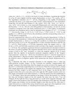
By taking into account the diagram presented in Figure 12, one can derive the following
expressions:
22
12 12
2. . .cosxdd dd
α
=+− (1)
For the variables in these equations, we have the values determined at two time moments t
1
and t
2
, so computing the speed of the object having attached the tag is obvious:
22
12 12
21
2. . .cosdd dd
x
v
ttt
α
+−
==
Δ−
(2)
4.2 Software diagram of the speed computing program
We have developed a software program to compute the speed based on the location
information provided by the RFID reader and have made various performance tests using a
RFID Radar. The program was developed on a platform running Windows XP as an
operating system. We used Power Basic for writing and compiling the program, with very
good results regarding the processing speed. Data was exchanged with the RFID system by
using the RS232C serial interface. Results were delivered in a text box and were written in a
text file on the local disk.
Figure 13 presents the software diagram for calculating the speed. The process begins with a
system initialization procedure, followed by a calibration routine. After these operations, we
Radio Frequency Identification Fundamentals and Applications, Bringing Research to Practice
122
Fig. 13. Software diagram to calculate the transponder speed
wait for a transponder to come in the active range of the antennas. When the transponder
enters the range, we get the current information, such as the unique ID, the location and
time information. We do not need, and consequently, do not process any information stored
in the transponder internal memory. After a delay of about 100 ms, the program enters a
routine expecting the next reading. When receiving the same ID, the program gets the new
values for location and time information, and then, it computes and displays the distance
travelled by the transponder, and its speed.
Applications of RFID Systems - Localization and Speed Measurement
123
When the current transponder ID is out of range, the program will acquire a new unique ID
to calculate the new speed. If another transponder comes into the active range of the reader
while the software is acquiring the speed for one transponder, the last one will not be read.
In Figure 14 one may see the distance calibration process necessary to be made at system
initialization, before any speed measurement could be done.
Fig. 14. RFID system calibration using a transponder at 9 m distance from the antennas
A photo of the set-up in the anechoic chamber used for speed measurement tests is shown
bellow:
Fig. 15. View of experimental setup in the anechoic chamber for speed measurements
We capture the output screen of the software we developed in Figure 16, showing the
results with two active transponders moving in opposite directions with the same very low
speed and, in Figure 17, a screen capture and a photo taken in order to compare the speed
measured by the RFID system and the K Band radar gun.
Radio Frequency Identification Fundamentals and Applications, Bringing Research to Practice
124
Fig. 16. Measurement screen showing two active transponders moving in opposite
directions with the same speed
Fig. 17. Comparison between the speeds measured by the RFID system and a K-band radar
4.3 Theoretical and practical limitations for speed measurement
Considering the distance between the two receiving antennas of 31 cm (factory default), the
system is able to solve angles between -30 and +30 degrees. The time spacing between two
transponder transmissions is, as in Figure 2, about 333 milliseconds (three transmissions per
second). Assuming that a transponder is moving such that the distance to the antenna
system is constant, one can calculate the maximum theoretical speed that may be measured
by using only the angle of arrival information. We also assume that we read two times the
transponder in the whole working range of 60 degrees, the minimum information needed to
compute the speed. If the reader does not receive the second transmitted signal, due to
propagation issues, the speed can not be computed. The software will initiate a new
measurement sequence by acquiring a new transponder ID. Table 1 presents a summary of
the theoretical maximum speed as a function of the distance from the transponder to the
antennas.
Distance to the antenna system (meters) 10 20 30 40 50
Distance traveled by the transponder (meters) 5.8 11 17 23 28
Speed (km/h) 62 124 187 249 311
Table 1. The theoretical maximum speed as a function of the distance between the
transponder and the antenna system
In practical cases, more than two transmissions will be necessary in order to compute and
have trusted information regarding the speed. Moreover, by reducing the angle between
Applications of RFID Systems - Localization and Speed Measurement
125
two transmission points, let us say the system is not able to process the information in a
timely manner or the radio signal is disturbed/attenuated due to propagation, the
maximum measurable speed is much lower.
For the tests we made in a laboratory-controlled environment, with very low RF noise floor,
we obtained the results presented in Table 2.
Distance to the antenna system (meters) 10 20 30 40 50
Speed (km/h) 6 24 32 36 n/a
Table 2. The maximum measured speed as a function of the distance between the
transponder and the antenna system
Due to propagation issues generated by multiple reflections, we were not able to measure
transponder speeds for distances over 40 meters.
5. Electromagnetic compatibility measurements on the RFID location system
We made a set of two measurements, one using a portable equipment for radiated emissions
safety measurements (Narda SRM-3000) and a real life outdoor set-up and one using a
certified set-up in an ISO 17025 accredited Electromagnetic Compatibility Laboratory -
emclab.ro.
The RFID system we used for location and speed measurements is supposed to use a central
frequency of 870.00 MHz with a bandwidth of 10 kHz. The frequency was chosen
intentionally in order to be outside the GSM 900 band used in Europe (880.0 MHz - 915.0
MHz / 925.0 MHz - 960.0 MHz).
As we might see in the capture from the spectrum analyzer (see Figure 18), the electric field
strength, at distance of 20 m in front of the reader antenna, is about 1.2 V/m, a value
sufficiently low to be in accordance with the EMC safety levels in Europe and in the US.
There are also visible, above the RF noise floor, the emissions from the GSM base stations (at
940 MHz and 960 MHz) located at about 600 meters from the location the tests were made.
Problems appear right in front and very close to the antenna system. In Figure 19 we have
the field strength at a distance of 3 meters in front of the antennas. At this distance the
emission level is about 39 V/m, a value high enough to worry. At about 30 cm near the
emission antenna the field was about 200 V/m, the maximum value the spectrum analyzer
could measure.
Regarding the bandwidth of the signal, we observe to be in the range of 10 to 25 kHz, small
enough not to produce interference with other radio spectrum users. If many such devices
are to be used simultaneously, on different central frequencies, there will be no problem if
the spacing between to channel will be as low as 30 kHz.
A second set of measurements were made in an ISO 17025 accredited laboratory, using a
certified set-up. The radiated emissions measurements have been made in a 3 m TDK semi-
anechoic chamber using a Rohde & Schwarz - ESU 26 EMI Test Receiver, calibrated
antennas and cables. The turntable and the antenna mast were operated by using an in-
house made software program. Two international standards specify the emissions level and
the performance characteristics of SRD-RFID equipments respectively: EN 55022 (CISPR 22)
- "Information technology equipment - Radio disturbance characteristics - Limits and
methods of measurements" for the emissions and EN 300-220 - "Electromagnetic
Radio Frequency Identification Fundamentals and Applications, Bringing Research to Practice
126
Fig. 18. Electric field magnitude at 20 m distance in front of the antenna
Fig. 19. Electric field magnitude at 3 m distance in front of the antenna
Applications of RFID Systems - Localization and Speed Measurement
127
compatibility and Radio spectrum Matters (ERM); Short Range Devices (SRD)" for the
operating performances and functional characteristics. A standard configuration was used
for the test, as the equipment to be measured (EUT - Equipment Under Test) was positioned
on a turn table at 0.8 meters above the ground and at 3 meters distance from the receiving
antenna tip. During the measurements, the receiving antenna moved from 1 m to 4 m height
and the EUT rotated 360 degrees, to find out the maximum emission level in the 30 to 1000
MHz band (as specified in the standards, in the final scan procedure, the operating
frequencies were excluded from the measurement interval). We placed the transponders just
in front of the RFID Radar antenna system. As stated in the standards above, the readings
were made continuously, one measure per second using quasi-peak and peak detectors for
the pre-scan and the final scan measurements respectively.
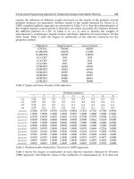
Table 3 shows the levels measured using this setup (we preserved also the peaks from the
operating frequency range in order to compare them with the peaks outside this band and
with the results from the first outdoor set-up). The limits used for calculations (QP Margin
column) were 40 dB for 30 to 230 MHz and 47 dB for 230 MHz to 1000 MHz (as stated in
CISPR 22 for 3 m test distance we have to add 20 dB per decade). We observe that outside
the operating frequency band the emissions were below the limits with one notable
Freq
(MHz)
Pol.
Tbl.
Ang.
(deg)
QP
(dBuV)
Freq.
peak
(MHz)
QP
Margin
(dB)
QP
Trace
(dB)
188.7 H 65.5 33.20 184.01 -6.80 18.21
202.5 V 44.2 33.98 194.61 -6.02 18.11
865.2 H 18.2 89.00 869.91 42.00 65.36
865.2 V 153.2 72.54 869.91 25.54 48.90
867.0 H 17.7 88.70 869.92 41.70 65.06
867.0 V 150.5 42.38 869.92 -4.62 18.74
868.3 H 18.5 80.43 869.97 33.43 56.79
869.3 H 17.4 72.57 870.00 25.57 48.93
869.3 V 150.9 55.89 870.00 9.11 32.25
869.9 H 18.8 89.46 869.90 42.46 65.82
869.9 V 152.0 72.85 869.90 25.85 49.21
945.6 H 12.6 133.10 945.75 86.10 109.17
945.8 V 62.0 117.61 945.80 70.61 93.68
Table 3. The emission levels measured in the semi-anechoic chamber at 3 meters distance
from the RFID Radar.
exception, at 945 MHz, where the electric field magnitude was over the limits specified in
the standards. For the main operating frequency band, the emissions were very high,
causing possible EMI problems for other electrical equipments operating nearby.
Radio Frequency Identification Fundamentals and Applications, Bringing Research to Practice
128
Regarding the safety aspects, there are problems due to very high emissions level, the field
intensity measured being well higher than the maximum values permitted by the standard.
In ETSI EN 300 220-1 V2.2.1 (2008-04) - Electromagnetic compatibility and Radio spectrum
Matters (ERM), the power limit for devices operating between 30 MHz and 1.000 MHz, for
all the bands reserved for short range devices, is 500 mW. There are other regulations in the
EU where power levels up to 2 Watts are permitted for RFID systems with non/modulated
carrier. Due to the operating principle, the RF power generator operating continuously, long
time exposure to the EM field produced by the antenna RFID Radar system could be
dangerous for humans.
6. Conclusion
RFID location systems for indoor and outdoor positioning are a promise for the future, even
the performances of these systems are affected by many factors. We identified here that for a
system working in the RF band near 900 MHz, the objects interposed between the antenna
system and the tags to be located may have a great influence in terms of accuracy of the
measurement results.
In closed areas multiple reflection paths may disturb the measurement systems, a percent of
only 40 to 60 of total measurements are enough accurate to locate an object. In such
conditions, there are small chances for this kind of systems to be used for high precision
indoor applications requiring more than several tens of centimetres accuracy. The results
obtained from the measurements we made in open area test sites are more promising, more
than 93 percent of total result were not affected by notable errors.
For speed measurement of mobile objects by using RFID systems, we may conclude there
are many aspects to solve before such systems may be used in commercial applications.
Despite the precision for both passive and active transponders positioning is in the range of
10-30 centimetres for methods based on the time of arrival and angle of arrival, the
performances obtained for speed measurements are not good enough when a large number
of mobile objects are simultaneously in range. For a single transponder or a reduced number
of transponders and small speeds, bellow 40 km/h, the speed measurement errors were
below 30 %. For better speed measurement results we must combine the use of a RFID
system for reading IDs and transponder internal memory contents with a classical radar
system and process the results in a software interface.
Regarding the EMC aspects of this RFID location system, we may say, based on
measurements presented here, that the electric field are high enough not to use this system
indoors at distances less than 5 meters, if humans are present on a regular basis in that area.
For applications in open areas, like access control for auto vehicles and many similar others,
this kind of systems are very good.
7. References
Bahl, P.; Venkata, N.; Padmanabhan, N. & Balachandran, A. (2000). "Enhancements to the
RADAR user location and tracking systems" Microsoft Research Technical Report
MSR-TR-2000-12, February 2000
Coca, E. & Popa, V. (2007). "Experimental Results and EMC Considerations on RFID
Location Systems", Proceedings of the 1st International RFID Eurasia Conference, 4-6
Applications of RFID Systems - Localization and Speed Measurement
129
September 2007, Istanbul, Turkey, pp. 279-283, ISBN 978-975-01566-0-1, Digital
Object Identifier 10.1109/RFIDEURASIA.2007.4368138
Coca, E.; Popa, V.; Găitan, V.; Turcu, C. O. & Turcu, Cr. (2008). "Speed Measurement
of a Moving Object by Using a RFID Location System and Active
Transponders", Electronics and Electrical Engineering, Lithuania, Nr. 8(88), 2008, ISSN
1392-1215
Van Diggelen, F. & Abraham, C. (2001). "Indoor GPS Technology", CTIA, Dallas, Texas,
USA, May 2001
Evennou, F. & Marx, F. (2006). "Advanced Integration of WiFi and Inertial Navigation
Systems for Indoor Mobile Positioning", EURASIP Journal on Applied Signal
Processing, vol. 2006
FCC (1996). Docket no. 94-102, "Revision of the commission's rules to ensure compatibility
with enhanced 911 emergency calling", Tech. Rep. RM-8143, July 1996
Finkenzeller, K. (2003). "RFID Handbook: Fundamentals and Applications in Contactless
Smart Cards and Identification" John Wiley & Sons, New York, NY, USA, 2nd edition,
2003
Fontana, R. J. (2008). "Recent Applications of Ultra Wideband Radar and Communications
Systems",
Gillieron, P.Y. & Merminod, B. (2003). "Personal navigation system for indoor
applications", Proceedings of the 11th IAIN World Congress, Berlin, Germany, October
2003.
Gillieron, P.Y.; Buchel, D. & Spassov, I. (2004). "Indoor navigation performance analysis",
Proceedings of the 8th European Navigation Conference (GNSS ’04), Rotterdam, The
Netherlands, May 2004
Hightower, J. & Borriello, G. (2001). "A survey and taxonomy of location systems for
ubiquitous computing" Tech. Rep. UWCSE 01-08-03, University of Washington,
Washington, DC, USA, August 2001
D'Hoe, K.; Van Nieuwenhuyse, A.; Ottoy, G.; De Strycker, L.; De Backer, L.; Goemaere, J. &
Nauwelaers, B. (2009). "Influence of Different Types of Metal Plates on a High
Frequency RFID Loop Antenna: Study and Design", Advances in Electrical and
Computer Engineering, ISSN Print 1582-7445, ISSN On-line 1844-7600, vol. 9, no. 2,
pp. 3-8, 2009. doi: 10.4316/AECE.2009.02001
De Luca, D.; Mazzenga, F.; Monti, C. & Vari, M. (2006). "Performance Evaluation of Indoor
Localization Techniques Based on RF Power Measurements from Active or Passive
Devices", EURASIP Journal on Applied Signal Processing, vol. 2006, Article ID 74796,
11 pages, 2006. doi:10.1155/ASP/2006/74796
Ni, L. M.; Liu, Y. & Patil, A. P. (2003). "LANDMARC: Indoor Location Sensing Using Active
RFID", Proceedings of the First IEEE International Conference on Pervasive Computing
and Communications (PerCom'03), pp. 407-415, 2003
Priyantha, N. B.; Chakraborty, A. & Baladrishnan, H. (2000). "The cricket location-
support system", Proceedings of the 6th Annual International Conference on Mobile
Computing and Networking (MOBICOM ’00), pp. 32–43, Boston, Mass, USA, August
2000
Radio Frequency Identification Fundamentals and Applications, Bringing Research to Practice
130
Wolfle, G.; Wertz, P. & Landstorfer, F. M. (1999). "Performance, accuracy and generalization
capability of indoor propagation models in different types of buildings,” in
Proceedings of 10th IEEE International Symposium on Personal, Indoor and Mobile
Radio Communications (PIMRC ’99), Osaka, Japan, September 1999
9
IP-based RFID Location System
Phuoc Nguyen Tran and Nadia Boukhatem
Computer Science and Network Department, Telecom ParisTech
46 rue Barrault, 75013 Paris,
France
1. Introduction
The Radio Frequency Identification (RFID) landscape has been radically changing since
decades. It has been widely deployed by commercial and industrial organizations as well as
government agencies with a wide range of applications. The RFID technology makes it
possible to identify an object, to track it and learn its characteristics remotely, thanks to a
label emitting radio waves, integrated or attached to the object. The RFID technology
enables reading of labels even without direct line of sight and can pass through thin layers
of material (paint, snow, etc.).
In the last few years, the RFID systems have evolved significantly in terms of technology
and cost, enabling the RFID systems to stand out as the reference identification technology
in numerous fields of applications such as asset tracking, logistics and supply chain
management, animal tracking, healthcare, warehouse management, manufacturing
engineering, automotive, contactless payments, etc. and mandated by industry giants (e.g.
Wall-Mart, Target, Tesco and Albertson , etc.) and various government agencies (e.g. U.S.
Department of Defense and Department of Homeland security, etc.).
One of the main advantages of the RFID technology is to provide a low cost and easy to
install indoor location system compared to other positioning systems, such as Global
Positioning System (GPS), Wi-Fi, Ultra-Wideband (UWB), Infrared (IR), and sensor based
systems, etc.
A number of location sensing systems based on RFID technology have been proposed for
indoor location services. SpotON [high] supports indoor location service using RFID
technology based on radio signal strength analysis. LANMARC [ni] aims at increasing the
accuracy in determining the RFID tag location and economizing the deployment cost of the
system. To increase the accuracy, the system defines extra fixed location reference tags to
help location calibration. In addition, an algorithm which reflects the relations of signal
strengths by power level is developed in order to compute accurately the physical distance
between the objects and the reader. FLEXOR [sue] is an improvement of LANDMARC to
reduce the computational overhead in determining the location of the objects. The system
divides the location area into cells which reduce the information used for localization
calculation and decreases the computation load for the localization service. FERRET [liu]
allows not only locating the RFID tagged objects, but also displaying the objects. The system
uses an RFID reader embedded in a camera. FERRET uses also the algorithm which reflects
the relations of signal strengths by power level to locate the objects. When the object is
Radio Frequency Identification Fundamentals and Applications, Bringing Research to Practice
132
found, the camera is turned on and displays their locations in real-time. In [teso], a sensing
surface location system is proposed. The system is capable of tracking the objects within a
closed environment. The objects (e.g devices, people, robots, ect.) integrate passive RFID
readers. The RFID tags are installed as a grid representing the sensing surface. When the
objects are on the surface, their locations are determined by mapping the RFID tag detected
by the RFID readers and the physical surface of the RFID tags that it represents.
Besides, some solutions use Wi-Fi based Active RFID tags to expand the coverage zone
using the Wi-Fi technology and provide complete wireless asset tracking and monitoring
[aero] [ekah].
Considering the RFID management systems, the EPC global network developed by
EPCglobal [jud][klau][epc] is the most representative. EPCglobal aims at standardizing the
electronic product code (EPC) and the automatic identification system in the specific context
of supply chain.
With the target to develop open RFID management systems and ease the integration of
existing network services along with RFID location functionality, a number of works have
been proposed.
SOA-oriented networked RFID system [zhang] proposes RFID location tracking service
using web services. This system enables a distributed deployment of RFID solution which
hides the diversity of the RFID hardware and underlying I/O communication protocols.
Other works have investigated the use of session initiation protocol (SIP) [sip] as a control
protocol for RFID management. SIP-based RFID management system (SRMS) [cho] uses SIP
to manage the RFID tags. SRMS enhances the existing SIP architecture to perform RFID tags
location registration and tracking procedures.
Our work is motivated by developing an IP-based RFID system management thus enabling
low cost and large scale deployment of the RFID technology as well as openness and ease of
integration with the existing IP-based services. In particular, a SIP implementation will have
the benefit of providing a flexible integration of RFID location with the other corporate
network services
Several motivations underpin our work:
• Propose a SIP-based RFID location system for indoor location. The current location of
an object is determined by the identity of the reader when the object moves under its
coverage zone.
• Integrate the RFID location services to the other IP services of the corporate network.
This provides an integrated and flexible solution.
• More and more communication services such as location based services (LBS) are
developed using the location information. The RFID based location system constitutes a
good basis for providing such customized services.
1.1 Positioning systems
A positioning system allows determining the location of an object in space based on real-
time collected information. It is also able to track the current location of an object moving
through a space.
GPS system [joy][ivan] is today a widely deployed system. It provides the location of an
object on the Earth (e.g. latitude and longitude). The current location of the objects moving
through space could be visual using navigating map provided by the GPS providers. The
GPS system is consisting of satellites in located geostationary orbit around the Earth and the
GPS devices sending the updated location information to the satellites. If GPS seems to be a