Microwave and millimeter wave technologies from photonic bandgap devices to antenna and applications Part 3 doc
Bạn đang xem bản rút gọn của tài liệu. Xem và tải ngay bản đầy đủ của tài liệu tại đây (882.46 KB, 30 trang )
IntegratedSiliconMicrowaveandMillimeterwavePassiveComponentsandFunctions 51
overall behaviour and performances of the function. As it is shown, one can distinguish
between lumped elements structures (Figure 24) or distributed elements ones (Figure 25).
(a)
(b)
(c)
Fig. 24. Lumped topologies of matching networks, (a) two components, (b) T structure, (c)
structure
Fig. 25. Distributed topologies of matching networks with characteristic impedance Z and
electric length
The design of the function is strictly equivalent in hybrid or integrated circuit (IC)
technology but the size of the circuit is noticeably different since it is typically 1 cm
2
for the
first technology and 1 mm
2
for the second one. Furthermore, the reachable operating
frequencies are higher in IC technology than in hybrid one (typically 25 GHz against
2,5 GHz) but, on the contrary, the insertion losses are typically better in hybrid technology
(0,2 dB against 3,5 dB). This last problem is due to the IC substrate RF behaviour and to low
quality factors of IC transmission lines.
One of the main advantages of the IC technology for industrial matching networks is its
very high reliability rate. Nevertheless, it has to be said that IC structures suffer from non-
linearity behaviour at high power, even if some PIN diodes or transistors structures claim to
operate up to 40 dBm. In the literature, very few data are reported on noise behaviour of IC
matching networks although it shall not be a good point for that kind of structure.
Of course, due to the recent development of multiband and multistandard communications,
some tuneable matching networks were realized and the flexibility of IC technology and the
control of diodes or transistors brings some advantages in that frame (Sinsky & Westgate,
1997). In fact, the integrated circuit (IC) technology drastically reduces dimension of lumped
components so of the devices, the order of magnitude becoming the millimetre. For a
classical CMOS IC, such impedance tuning device is quite large but it is usual in RF front-
end applications. The tunability is obtained as in hybrid technology, with the ability of
switching transistors. For RF distributed components, typical IC substrates, like SOI or float-
zone Si substrates are not convenient since the losses are too strong, with sometimes
insertion loss near 10dB. The quality factor of lines is poor because of conductors and
dielectric losses. In (McIntosh et al, 1999; De Lima et al, 2000) devices were found from
1GHz to 20GHz. Higher frequency devices are difficult to design because of the dielectrics
and conductors losses. Nevertheless, the main advantage of this technology is that the
fabrication process is standard, and research prototype can be easily transferred to industry.
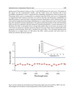
Recently (Hoarau et al, 2008), have designed an integrated
structure with a CMOS AMS
0.35
m technology of varactors and spiral inductors (Figure 26). Simulated results obtained
with ADS show that only a quarter of the smith chart is covered on a 1 GHz band around
the center frequency of 2 GHz. L structures could also be used to reduce the total number of
components and the losses.
Fig. 26. Smith chart of simulated results of a CMOS AMS 0.35m device for 3 frequencies
6. References
Abrie, P. L. D. (1985). The design of impedance-matching networks for radio-frequency and
microwave amplifiers, Artech House
Allers, K H., Brenner, P. & Schrenk, M. (2003). Dielectric reliability and material properties
of Al
2
O
3
in metal insulator metal capacitors (MIMCAP) for RF bipolar technologies
in comparison to SiO
2
, SiN and Ta
2
O
5
, Proc. of BCTM 2003, pp. 35-38, Toulouse
(France) , October 2003
Arnould, J D.; Benech, Ph.; Cremer, S.; Torres, J. & Farcy, A. (2004). RF MIM capacitors
using Si
3
N
4
dielectric in standard industrial BiCMOS technology, Proc. of IEEE ISIE
04
, pp. 27-30, Ajaccio (France) , May 2004
Berthelot, A. ; Caillat, C. ; Huard, V. ; Barnola, S. ; Boeck, B. ; Del-Puppo, H.; Emonet, N. &
Lalanne, F. (2006). Highly Reliable TiN/ZrO
2
/TiN 3D Stacked Capacitors for 45 nm
Embedded DRAM Technologies,
Proc. of ESSDERC 2006, pp. 343–346, Montreux,
Switzerland, Sept. 2006
Burghartz, J.N.; Soyuer, M.; Jenkins, K.A.; Kies, M.; Dolan, M.; Stein, K.J.; Malinowski, J. &
Harame, D.L. (1997). Integrated RF components in a SiGe bipolar technology.
IEEE
Journal of Solid-State Circuits
, vol. 32, n° 9 ( Sept. 1997), pp. 1440-1445
Büyüktas, K.; Geiselbrechtinger, A.; Decker S. & Koller K. (2009). Simulation and modelling
of a high-performance trench capacitor for RF applications.
Semicond. Sci. Technol.
vol. 24, n° 7, (July 2009), 10 p
Cai, W.Z.; Shastri, S.C.; Azam, M.; Hoggatt, C.; Loechelt, G.H.; Grivna, G.M.; Wen, Y. &
Dow, S. (2004). Development and extraction of high-frequency SPICE models for
Metal-Insulator-Metal capacitors,
Proc. of ICMTS '04, pp. 231-234, Hyogo (Japan),
March 2004
MicrowaveandMillimeterWaveTechnologies:
fromPhotonicBandgapDevicestoAntennaandApplications52
Chen Z.; Guo L.; Yu M. & Zhang Y. (2002). A study of MIMIM on-chip capacitor using
Cu/SiO
2
interconnect technology. IEEE Microwave and Wireless Components Letters,
vol. 12, n° 7, july 2002, pp. 246-248
Cheung, T.S.D. & Long, J.R. (2006). Shielded passive devices for silicon-based monolithic
microwave and millimeter-wave integrated circuits,
IEEE Journal of Solid-state
circuits,
vol. 41, n°. 5, May 2006, pp. 1183-1200.
Contopanagos, H. & Nassiopoulou, A.G. (2007). Integrated inductors on porous silicon.
Physica status solidi (a), vol. 204, n° 5 (Apr. 2007), pp. 1454 - 1458
Defay, E.; Wolozan, D.; Garrec, P.; Andre, B.; Ulmer, L.; Aid, M.; Blanc, J P.; Serret, E.;
Delpech, P. ; Giraudin, J C. ; Guillan, J. ; Pellissier, D. & Ancey, P. (2006). Above IC
integrated SrTiO high K MIM capacitors,
Proc. of ESSDERC, pp. 186–189, Montreux,
Switzerland, Sept. 2006
De Lima, R. N.; Huyart, B.; Bergeault, E. & Jallet, L. (2000). MMIC impedance matching
system,
Electronics Letters, vol. 36 (Aug 2000), pp. 1393-1394
Gianesello, F.; Gloria, D.; Montusclat, S.; Raynaud, C.; Boret, S.; Clement, C.; Dambrine, G.;
Lepilliet, S.; Saguin, F.; Scheer, P.; Benech, P. & Fournier, J.M. (2006). 65 nm
RFCMOS technologies with bulk and HR SOI substrate for millimeter wave
passives and circuits characterized up to 220 GHZ,
Proceedings of Microwave
Symposium Digest, 2006. IEEE MTT-S International
, pp. 1927-1930, San Francisco,
CA, June 2006.
Guo P.J. & Chuang H.R. (2008). A 60-GHz Millimeter-wave CMOS RFIC-on-chip Meander-
line Planar Inverted-F Antenna for WPAN Applications,
IEEE Trans. Antennas
Propagation, July 2008.
Hasegawa, H. & Okizaki, H. (1977). MIS and Schottky slow-wave coplanar striplines on
GaAs substrates.
IEEE Electronics Letters, Vol. 13, No. 22, Oct. 1977, pp. 663-664.
Hoarau, C.; Corrao, N.; Arnould, J D. ; Ferrari, P. & Xavier; P. (2008). Complete Design
And Measurement Methodology For A RF Tunable Impedance Matching
Network", IEEE Trans. on MTT, vol. 56, n° 11 (Nov. 2008), pp. 2620-2627
Huang, K. C. & Edwards, D. J. (2006). 60 GHz multibeam antenna array for gigabit wireless
communication networks.
IEEE Trans. Antennas Propagation, vol. 54, no. 12, pp.
3912–3914, Dec. 2006.
International technology roadmap for semiconductors (2003).
Jeannot, S.; Bajolet, A.; Manceau, J P.; Cremer, S.; Deloffre, E.; Oddou, J P.; Perrot, C.;
Benoit, D.; Richard, C.; Bouillon, P. & Bruyere, S. (2007). Toward next high
performances MIM generation: up to 30fF/µm² with 3D architecture and high-k
materials,
Proc. of IEEE IEDM 2007, pp. 997-1000, Dec. 2007, Washington DC (USA)
Jiang, H.; Wang, Y.; Yeh, J L.A. & Tien, N.C. (2000). Fabrication of high-performance on-
chip suspended spiral inductors by micromachining and electroless copper plating.
Proc. of IEEE MTT-S IMS, pp. 279-282, Boston MA (USA), June 2000
Kaddour, D.; Issa H.; Abdelaziz, M.; Podevin, F.; Pistono, E.; Duchamp, J M. & Ferrari P.
(2008). Design guidelines for low-loss slow-wave coplanar transmission lines in RF-
CMOS technology,
M. and Opt. Tech. Lett., vol. 50, n°. 12, Dec. 2008, pp. 3029-3036.
Kim, K. (2000). Design and Characterisation of Components for Inter and Intra-Chip
Wireless Communications.
Dissertation, University of Florida, Gainsville, 2000.
Kim, K; Yoon, H. & O. K.K. (2000). On-chip wireless interconnection with integrated
antennas,
IEDM Technical Digest, San Francisco CA (USA), Dec. 2000, pp. 485-488.
Kim, W. & Swaminathan, M. (2005). Simulation of lossy package transmission loines using
extracted data from one-port TDR measurements and nonphysical RLCG model.
IEEE Trans. on Advanced Packaging, vol. 28, n°. 4, Nov. 2005, pp. 736-744.
Lee, K.Y.; Mohammadi, S.; Bhattacharya, P.K. & Katehi, L.P.B. (2006-1). Compact Models
Based on Transmission-Line Concept for Integrated Capacitors and Inductors.
IEEE
Trans. on MTT
, vol. 54, n°. 12 (Dec. 2006), pp. 4141-4148
Lee, K Y.; Mohammadi, S.; Bhattacharya, P.K. & Katehi, L.P.B. (2006-2). A Wideband
Compact Model for Integrated Inductors.
IEEE Microwave and Wireless Components
Letters
, vol. 16, n° 9 (Sept. 2006), pp. 490-492
Lemoigne, P.; Arnould, J D.; Bailly, P E.; Corrao, N.; Benech, P.; Thomas, M.; Farcy, A. &
Torres, J. (2006). Extraction of equivalent electrical models for damascene MIM
capacitors in a standard 120 nm CMOS technology for ultra wide band
applications,
Proc. of IEEE IECON 2006, pp. 3036-3039, Paris (France) , Nov. 2006
Masuda, T.; Shiramizu, N.; Nakamura, T. & Washio, K. (2008). Characterization and
modelling of microstrip transmission lines with slow-wave effect.
Proceedings of
SiRF,
pp. 155-158, Orlando, USA, January 2008.
McIntosh, C. E.; Pollard, R. D. & Miles, R. E. (1999). Novel MMIC source-impedance tuners
for on-wafer microwave noise-parameter measurements. IEEE Trans. on MTT, vol.
47, n° 2 (Feb. 1999), pp. 125-131
Mehrotra V. & Boning D. (2001). Technology scaling impact of variation on clock skew and
interconnect,
Proc. of the IEEE 2001 IITC, San Francisco, CA
Melendy, D.; Francis, P.; Pichler, C.; Kyuwoon, H.; Srinivasan, G. & Weisshaar, A. (2002).
Wide-band Compact Modeling of Spiral Inductors in RFICs,
Digest of Microwave
Symposium
, Seattle (USA), pp.717–720, June 2002.
Milanovic, V.; Ozgur, M.; Degroot, D.C.; Jargon, J.A.; Gaitan, M. & Zaghloul, M.E. (1998).
Characterization of Broad-Band Transmission for Coplanar Waveguides on CMOS
Silicon Substrates.
IEEE Trans. on MTT, vol. 46, n°. 5, May 1998, pp. 632-640.
Miller D.A.B. (2002). Optical interconnects to silicon.
IEEE J. Sel. Top. Quantum Electron., vol.
6, issue 6 (Nov./Dec. 2002), pp. 1312–1317
Mondon F. & Blonkowskic S. (2003). Electrical characterisation and reliability of HfO
2
and
Al
2
O
3
–HfO
2
MIM capacitors. Microelectronics Reliability, vol. 43, n° 8 (August 2003),
pp. 1259-1266
Nesic A.; Nesic, D.; Brankovic, V.; Sasaki, K. & Kawasaki, K. (2001). Antenna Solution for
Future Communication Devices in mm-Wave Range.
Microwave Review, Dec. 2001.
Nguyen, N.M. & Meyer, R.G. (1990). Si IC-Compatible Inductors and LC Passive Filters.
IEEE Journal of Solid-State Circuits, vol. 25, n°4 (Aug. 1990), pp. 1028-1031
Pastore, C.; Gianesello F.; Gloria, D.; Serret, E. & Benech, Ph. (2008-1). Impact of dummy
metal filling strategy dedicated to inductors integrated in advanced thick copper
RF BEOL.
Microelectronic Engineering, vol. 85, n° 10 (October 2008), pp. 1962-1966
Pastore, C.; Gianesello F.; Gloria, D.; Serret, E.; Bouillon, E.; Rauber, P. & Benech, Ph. (2008-
2). Double thick copper BEOL in advanced HR SOI RF CMOS technology:
Integration of high performance inductors for RF front end module,
Proc. of IEEE
International 2008 SOI Conference
, pp. 137-138, Oct. 2008, New York (USA)
Pozar, D. M. (1998).
Microwave Engineering, 2nd ed. John Wiley and Sons, Inc. 1998
IntegratedSiliconMicrowaveandMillimeterwavePassiveComponentsandFunctions 53
Chen Z.; Guo L.; Yu M. & Zhang Y. (2002). A study of MIMIM on-chip capacitor using
Cu/SiO
2
interconnect technology. IEEE Microwave and Wireless Components Letters,
vol. 12, n° 7, july 2002, pp. 246-248
Cheung, T.S.D. & Long, J.R. (2006). Shielded passive devices for silicon-based monolithic
microwave and millimeter-wave integrated circuits,
IEEE Journal of Solid-state
circuits,
vol. 41, n°. 5, May 2006, pp. 1183-1200.
Contopanagos, H. & Nassiopoulou, A.G. (2007). Integrated inductors on porous silicon.
Physica status solidi (a), vol. 204, n° 5 (Apr. 2007), pp. 1454 - 1458
Defay, E.; Wolozan, D.; Garrec, P.; Andre, B.; Ulmer, L.; Aid, M.; Blanc, J P.; Serret, E.;
Delpech, P. ; Giraudin, J C. ; Guillan, J. ; Pellissier, D. & Ancey, P. (2006). Above IC
integrated SrTiO high K MIM capacitors,
Proc. of ESSDERC, pp. 186–189, Montreux,
Switzerland, Sept. 2006
De Lima, R. N.; Huyart, B.; Bergeault, E. & Jallet, L. (2000). MMIC impedance matching
system,
Electronics Letters, vol. 36 (Aug 2000), pp. 1393-1394
Gianesello, F.; Gloria, D.; Montusclat, S.; Raynaud, C.; Boret, S.; Clement, C.; Dambrine, G.;
Lepilliet, S.; Saguin, F.; Scheer, P.; Benech, P. & Fournier, J.M. (2006). 65 nm
RFCMOS technologies with bulk and HR SOI substrate for millimeter wave
passives and circuits characterized up to 220 GHZ,
Proceedings of Microwave
Symposium Digest, 2006. IEEE MTT-S International
, pp. 1927-1930, San Francisco,
CA, June 2006.
Guo P.J. & Chuang H.R. (2008). A 60-GHz Millimeter-wave CMOS RFIC-on-chip Meander-
line Planar Inverted-F Antenna for WPAN Applications,
IEEE Trans. Antennas
Propagation, July 2008.
Hasegawa, H. & Okizaki, H. (1977). MIS and Schottky slow-wave coplanar striplines on
GaAs substrates.
IEEE Electronics Letters, Vol. 13, No. 22, Oct. 1977, pp. 663-664.
Hoarau, C.; Corrao, N.; Arnould, J D. ; Ferrari, P. & Xavier; P. (2008). Complete Design
And Measurement Methodology For A RF Tunable Impedance Matching
Network", IEEE Trans. on MTT, vol. 56, n° 11 (Nov. 2008), pp. 2620-2627
Huang, K. C. & Edwards, D. J. (2006). 60 GHz multibeam antenna array for gigabit wireless
communication networks.
IEEE Trans. Antennas Propagation, vol. 54, no. 12, pp.
3912–3914, Dec. 2006.
International technology roadmap for semiconductors (2003).
Jeannot, S.; Bajolet, A.; Manceau, J P.; Cremer, S.; Deloffre, E.; Oddou, J P.; Perrot, C.;
Benoit, D.; Richard, C.; Bouillon, P. & Bruyere, S. (2007). Toward next high
performances MIM generation: up to 30fF/µm² with 3D architecture and high-k
materials,
Proc. of IEEE IEDM 2007, pp. 997-1000, Dec. 2007, Washington DC (USA)
Jiang, H.; Wang, Y.; Yeh, J L.A. & Tien, N.C. (2000). Fabrication of high-performance on-
chip suspended spiral inductors by micromachining and electroless copper plating.
Proc. of IEEE MTT-S IMS, pp. 279-282, Boston MA (USA), June 2000
Kaddour, D.; Issa H.; Abdelaziz, M.; Podevin, F.; Pistono, E.; Duchamp, J M. & Ferrari P.
(2008). Design guidelines for low-loss slow-wave coplanar transmission lines in RF-
CMOS technology,
M. and Opt. Tech. Lett., vol. 50, n°. 12, Dec. 2008, pp. 3029-3036.
Kim, K. (2000). Design and Characterisation of Components for Inter and Intra-Chip
Wireless Communications.
Dissertation, University of Florida, Gainsville, 2000.
Kim, K; Yoon, H. & O. K.K. (2000). On-chip wireless interconnection with integrated
antennas,
IEDM Technical Digest, San Francisco CA (USA), Dec. 2000, pp. 485-488.
Kim, W. & Swaminathan, M. (2005). Simulation of lossy package transmission loines using
extracted data from one-port TDR measurements and nonphysical RLCG model.
IEEE Trans. on Advanced Packaging, vol. 28, n°. 4, Nov. 2005, pp. 736-744.
Lee, K.Y.; Mohammadi, S.; Bhattacharya, P.K. & Katehi, L.P.B. (2006-1). Compact Models
Based on Transmission-Line Concept for Integrated Capacitors and Inductors.
IEEE
Trans. on MTT
, vol. 54, n°. 12 (Dec. 2006), pp. 4141-4148
Lee, K Y.; Mohammadi, S.; Bhattacharya, P.K. & Katehi, L.P.B. (2006-2). A Wideband
Compact Model for Integrated Inductors.
IEEE Microwave and Wireless Components
Letters
, vol. 16, n° 9 (Sept. 2006), pp. 490-492
Lemoigne, P.; Arnould, J D.; Bailly, P E.; Corrao, N.; Benech, P.; Thomas, M.; Farcy, A. &
Torres, J. (2006). Extraction of equivalent electrical models for damascene MIM
capacitors in a standard 120 nm CMOS technology for ultra wide band
applications,
Proc. of IEEE IECON 2006, pp. 3036-3039, Paris (France) , Nov. 2006
Masuda, T.; Shiramizu, N.; Nakamura, T. & Washio, K. (2008). Characterization and
modelling of microstrip transmission lines with slow-wave effect.
Proceedings of
SiRF,
pp. 155-158, Orlando, USA, January 2008.
McIntosh, C. E.; Pollard, R. D. & Miles, R. E. (1999). Novel MMIC source-impedance tuners
for on-wafer microwave noise-parameter measurements. IEEE Trans. on MTT, vol.
47, n° 2 (Feb. 1999), pp. 125-131
Mehrotra V. & Boning D. (2001). Technology scaling impact of variation on clock skew and
interconnect,
Proc. of the IEEE 2001 IITC, San Francisco, CA
Melendy, D.; Francis, P.; Pichler, C.; Kyuwoon, H.; Srinivasan, G. & Weisshaar, A. (2002).
Wide-band Compact Modeling of Spiral Inductors in RFICs,
Digest of Microwave
Symposium
, Seattle (USA), pp.717–720, June 2002.
Milanovic, V.; Ozgur, M.; Degroot, D.C.; Jargon, J.A.; Gaitan, M. & Zaghloul, M.E. (1998).
Characterization of Broad-Band Transmission for Coplanar Waveguides on CMOS
Silicon Substrates.
IEEE Trans. on MTT, vol. 46, n°. 5, May 1998, pp. 632-640.
Miller D.A.B. (2002). Optical interconnects to silicon.
IEEE J. Sel. Top. Quantum Electron., vol.
6, issue 6 (Nov./Dec. 2002), pp. 1312–1317
Mondon F. & Blonkowskic S. (2003). Electrical characterisation and reliability of HfO
2
and
Al
2
O
3
–HfO
2
MIM capacitors. Microelectronics Reliability, vol. 43, n° 8 (August 2003),
pp. 1259-1266
Nesic A.; Nesic, D.; Brankovic, V.; Sasaki, K. & Kawasaki, K. (2001). Antenna Solution for
Future Communication Devices in mm-Wave Range.
Microwave Review, Dec. 2001.
Nguyen, N.M. & Meyer, R.G. (1990). Si IC-Compatible Inductors and LC Passive Filters.
IEEE Journal of Solid-State Circuits, vol. 25, n°4 (Aug. 1990), pp. 1028-1031
Pastore, C.; Gianesello F.; Gloria, D.; Serret, E. & Benech, Ph. (2008-1). Impact of dummy
metal filling strategy dedicated to inductors integrated in advanced thick copper
RF BEOL.
Microelectronic Engineering, vol. 85, n° 10 (October 2008), pp. 1962-1966
Pastore, C.; Gianesello F.; Gloria, D.; Serret, E.; Bouillon, E.; Rauber, P. & Benech, Ph. (2008-
2). Double thick copper BEOL in advanced HR SOI RF CMOS technology:
Integration of high performance inductors for RF front end module,
Proc. of IEEE
International 2008 SOI Conference
, pp. 137-138, Oct. 2008, New York (USA)
Pozar, D. M. (1998).
Microwave Engineering, 2nd ed. John Wiley and Sons, Inc. 1998
MicrowaveandMillimeterWaveTechnologies:
fromPhotonicBandgapDevicestoAntennaandApplications54
Rashid, A.B.M.H.; Watanabe, S.; Kikkawa, T. (2003). Crosstalk isolation of monopole
integrated antenna on Si for ULSI wireless interconnect,
Proc. of the IEEE 2003 IITC,
pp. 156-158, San Franscisco CA (USA), June 2003.
Royet, A S.; Cuchet, R.; Pellissier, D. & Ancey, P. (2003). On the investigation of spiral
inductors processed on Si substrates with thick porous Si layers,
Proc. of ESSDERC,
pp. 111-113, Sept. 2003, Estoril (P)
Sayag, A.; Levin, S.; Regev, D.; Zfira, D.; Shapira, S.; Goren, D. & Ritter, D. (2008). One stage
24 GHz LNA with 6.4 dB gain and 2.8 dB NF using 0.18 µm CMOS technology and
slow wave transmission lines.
Proc. of the 1st Conf. on Microwaves, Communications,
Antennas and Electronic Systems (COMCAS),
pp.1-10, Israel, May 2008.
Sinsky J. H. & Westgate C. R. (1997). Design of an electronically tunable microwave
impedance transformer. Int. Micro. Symp. Digest, pp. 647-650, Denver, June 1997
Souri, S.J.; Banerjee, K.; Mehrotra, A. & Saraswat, K.C. (2000). Multiple Si Layer ICs:
Motivation, performance analysis and design implications,
Proc. of the 37th Annual
Design Automation Conf., pp. 213–220, 2000 Los Angeles CA (USA), June 2000
Subramaniam, K.; Kordesch, A.V. & Esa, M. (2005). Design and modeling of metal finger
capacitors for RF applications.
Proc. APACE 2005, pp. 293-296, Dec. 2005, Johor
(Malaysia)
Subramaniam, K.; Kordesch, A.V. & Esa, M. (2007). Low and High Frequency
Characterization of Metal Finger Capacitors for RFICs,
Proc. of ISSSE '07, pp. 567-
570, Montreal (Canada), July-August 2007
Sun, X.; Carchon, G.; Kita, Y.; Tani, T. & De Raedt, W. (2006). Experimental Analysis of
Above IC Inductor Performance with Different Patterned Ground Shield
Configurations and Dummy Metals,
Proc. of the 36
th
EUMC, pp. 40-43, Manchester
(UK), Sept. 2006
Tiemeijer, L.; Pijper, R.; Havens, R. & Hubert, O. (2007). Low-loss patterned ground shield
interconnect transmission lines in advanced IC processes.
IEEE Trans. on Microwave
Theory and Techniques
, vol. 55, n°. 3, March 2007, pp. 561-570.
Triantafyllou, A.; Farcy, A.; Benech, Ph.; Ndagijimana, F., Exshaw, O.; Tinella, C.; Richard,
O.; Raynaud, C. & Torres, J. (2005). Intra chip wireless interconnections based on
high performances integrated antennas.
Solid State Electronics, vol. 49, issue 9 (Sept.
2005), pp. 1477-1483
Volakis J.L. (2007).
Antenna Engineering Handbook, 4th ed., McGraw Hill Professional, 2007.
Wang, P. & Kan,E. (2004). High-speed interconnects with underlayer orthogonal metal
grids.
IEEE Trans. on advanced packaging, vol. 27, n°. 3, Aug. 2004, pp. 497-507.
Wang, T-H. & Itoh, T. (1987). Compact grating structure for application to filters and
resonators in monolithic microwave integrated circuits.
IEEE Trans. on Microwave
Theory and Techniques,
vol. 35, n°. 12, Dec. 1987, pp. 1176-1182.
Wang, X.; Yin, W Y. & Mao, J F. (2008). Parameter Characterization of Silicon-Based
Patterned Shield and Patterned Ground Shield Coplanar Waveguides,
Proceedings
of GSMM08
, pp. 142-145, Nanjing, China, April 2008.
Yue, C. P. & Wong, S. S. (2000). Physical Modelling of Spiral Inductors on Silicon.
IEEE
Trans. on Electron Devices
, vol. 47, n° 3 (March 2000.), pp. 560-568
NegativeRefractiveIndexCompositeMetamaterialsforMicrowaveTechnology 55
Negative Refractive Index Composite Metamaterials for Microwave
Technology
NicolaBowler
x
Negative Refractive Index Composite
Metamaterials for Microwave Technology
Nicola Bowler
Iowa State University
USA
1. Introduction
Materials that exhibit negative index (NI) of refraction have several potential applications in
microwave technology. Examples include enhanced transmission line capability, power
enhancement/size reduction in antenna applications and, in the field of nondestructive
testing, improved sensitivity of patch sensors and detection of sub-wavelength defects in
dielectrics by utilizing a NI superlens.
Since NI materials do not occur naturally, several approaches exist for creating NI behaviour
artificially, by combinations of elements with certain properties that together yield negative
refractive index over a certain frequency band. Present realizations of NI materials often
employ metallic elements operating below the plasma frequency to provide negative
permittivity (ߝ൏Ͳ), in combination with a resonator (e.g. a split-ring resonator) that
provides negative permeability (ߤ൏Ͳ) near resonance. The high dielectric loss exhibited by
metals can severely dampen the desired NI effect. Metallic metamaterials also commonly
rely on periodic arrays of the elements, posing a challenge in fabrication. A different
approach is to employ purely dielectric materials to obtain NI behaviour by, for example,
relying on resonant modes in dielectric resonators to provide ߝ൏Ͳ and ߤ൏Ͳ near
resonance. Then, the challenge is to design a metamaterial such that the frequency bands in
which both ߝ and ߤ are negative overlap, giving NI behaviour in that band. Two potential
advantages to this approach compared with NI materials based on metallic elements are i)
decreased losses and ii) simplified fabrication processes since the NI effect does not
necessarily rely on periodic arrangement of the elements.
This chapter explains the physics underlying the design of purely dielectric NI
metamaterials and will discuss some ways in which these materials may be used to enhance
various microwave technologies.
2. Basic Theory of Left-Handed Light
2.1 Effective permittivity and permeability of a composite material
In this chapter, the design of materials with negative refractive index, ݊൏Ͳ, will proceed on
the basis of achieving negative real parts of effective permittivity, ߝ, and permeability, ߤ, in a
3
MicrowaveandMillimeterWaveTechnologies:
fromPhotonicBandgapDevicestoAntennaandApplications56
composite material. Such a material is termed ‘double-negative’ or ‘DNG’. First, let’s
discuss what is meant by effective parameters and .
Adopting notation in which the vector fields are denoted by bold font and second-order
tensors by a double overline, the constitutive relations can be written as
(1)
in which is electric displacement, is the electric field, is the magnetic induction field
and is the magnetic field. In the following development, however, it will be assumed that
the materials are isotropic so that and are scalar. Then,
(2)
The assumption of isotropic properties holds for cubic lattices and entirely random
structures of spherical particles embedded in a matrix, for example.
It is often convenient to work in terms of dimensionless relative permittivity and
permeability,
and
, respectively, which are related to and by the free-space values
F/m and
H/m as follows;
(3)
2.2 Double-negative means negative refractive index
Considering the following familiar definition of the refractive index,
(4)
it is not immediately obvious why, in the case of a double-negative (DNG) medium, with
and that as well. The answer lies in the fact that
,
and are,
in general, complex quantities. Practically speaking,
and
exhibit complex behaviour
at frequencies close to a resonance or relaxation. These kinds of processes exist at
microwave frequencies in many materials and some of them will be discussed in following
sections of this chapter. So, given that
and
may be complex, write
(5)
where it is assumed that fields are varying time-harmonically as
with the
angular frequency and the frequency in Hz. Then, from (4),
(6)
From (6) it is clear that in order to determine the sign of when and , the
phase angles and must be considered.
Notice, first, that if and then both and lie between the
limits and . [This can be shown by employing Euler’s theorem
and considering the properties of the cosine function.] This also means that
(7)
Secondly, the condition that is required for the medium to be passive, or non-absorbing, will
be applied. This has the effect of further restricting the range of . In the case of a
passive medium,
. Again from Euler’s theorem but now considering the properties
of the sine function, the restriction that the imaginary part of is negative and taking the
appropriate root from (6) leads to the condition
(8)
Finally it can be seen that satisfaction of both (7) and (8) requires
(9)
and, due to the fact that
when (9) applies, it follows that
(10)
for a passive medium in which and .
In contrast with the refractive index, the impedance of a medium, defined
(11)
retains its positive sign in a DNG medium (Caloz et al., 2001; Ziolkowski & Heyman, 2001).
2.3 Wave propagation in a negative-refractive-index medium
We have shown that a double-negative medium has a negative index of refraction. What
consequences follow for the propagation of an electromagnetic wave in such a medium?
A negative-refractive-index medium supports backward wave propagation described by a left-
handed vector triad of the electric field , magnetic field and wave vector (Veselago,
1968; Caloz et al., 2001). Both and the phase velocity vector
exhibit a sign opposite to
that which they possess in a conventional right-handed medium (RHM). This has led to
such materials also being known as left-handed materials (LHMs), but it should be noted
that left-handedness is not a necessary nor sufficient condition for negative refraction
(Zhang & Mascarenhas, 2007). Regarding the Poynting vector and the group velocity
in
an LHM, , and form a right-handed triad and still points in the same direction as the
propagation of energy, as in an RHM. Thus, in an LHM,
and
are of opposite sign and
the wave fronts propagate towards the source.
Now let’s consider how Snell’s law of refraction applies in the case of a NI medium.
Recalling that the ratio of the sine functions of the angles of incidence and refraction (to the
surface normal) of a wave crossing an interface between two media is equivalent to the ratio
of the velocities of the wave in the two media, Snell’s Law can be expressed as
(12)
or, equivalently, as
A conventional case in which
is
illustrated in Fig. 1a). In the case of one of the media having negative refractive index, then
the refracted wave propagates on the same side of the surface normal as the incident wave.
This is illustrated in Fig. 1b) for the case
, for which
and
due to the odd nature of the sine function. In the next section it will be shown how a planar
NegativeRefractiveIndexCompositeMetamaterialsforMicrowaveTechnology 57
composite material. Such a material is termed ‘double-negative’ or ‘DNG’. First, let’s
discuss what is meant by effective parameters and .
Adopting notation in which the vector fields are denoted by bold font and second-order
tensors by a double overline, the constitutive relations can be written as
(1)
in which is electric displacement, is the electric field, is the magnetic induction field
and is the magnetic field. In the following development, however, it will be assumed that
the materials are isotropic so that and are scalar. Then,
(2)
The assumption of isotropic properties holds for cubic lattices and entirely random
structures of spherical particles embedded in a matrix, for example.
It is often convenient to work in terms of dimensionless relative permittivity and
permeability,
and
, respectively, which are related to and by the free-space values
F/m and
H/m as follows;
(3)
2.2 Double-negative means negative refractive index
Considering the following familiar definition of the refractive index,
(4)
it is not immediately obvious why, in the case of a double-negative (DNG) medium, with
and that as well. The answer lies in the fact that
,
and are,
in general, complex quantities. Practically speaking,
and
exhibit complex behaviour
at frequencies close to a resonance or relaxation. These kinds of processes exist at
microwave frequencies in many materials and some of them will be discussed in following
sections of this chapter. So, given that
and
may be complex, write
(5)
where it is assumed that fields are varying time-harmonically as
with the
angular frequency and the frequency in Hz. Then, from (4),
(6)
From (6) it is clear that in order to determine the sign of when and , the
phase angles and must be considered.
Notice, first, that if and then both and lie between the
limits and . [This can be shown by employing Euler’s theorem
and considering the properties of the cosine function.] This also means that
(7)
Secondly, the condition that is required for the medium to be passive, or non-absorbing, will
be applied. This has the effect of further restricting the range of . In the case of a
passive medium,
. Again from Euler’s theorem but now considering the properties
of the sine function, the restriction that the imaginary part of is negative and taking the
appropriate root from (6) leads to the condition
(8)
Finally it can be seen that satisfaction of both (7) and (8) requires
(9)
and, due to the fact that
when (9) applies, it follows that
(10)
for a passive medium in which and .
In contrast with the refractive index, the impedance of a medium, defined
(11)
retains its positive sign in a DNG medium (Caloz et al., 2001; Ziolkowski & Heyman, 2001).
2.3 Wave propagation in a negative-refractive-index medium
We have shown that a double-negative medium has a negative index of refraction. What
consequences follow for the propagation of an electromagnetic wave in such a medium?
A negative-refractive-index medium supports backward wave propagation described by a left-
handed vector triad of the electric field , magnetic field and wave vector (Veselago,
1968; Caloz et al., 2001). Both and the phase velocity vector
exhibit a sign opposite to
that which they possess in a conventional right-handed medium (RHM). This has led to
such materials also being known as left-handed materials (LHMs), but it should be noted
that left-handedness is not a necessary nor sufficient condition for negative refraction
(Zhang & Mascarenhas, 2007). Regarding the Poynting vector and the group velocity
in
an LHM, , and form a right-handed triad and still points in the same direction as the
propagation of energy, as in an RHM. Thus, in an LHM,
and
are of opposite sign and
the wave fronts propagate towards the source.
Now let’s consider how Snell’s law of refraction applies in the case of a NI medium.
Recalling that the ratio of the sine functions of the angles of incidence and refraction (to the
surface normal) of a wave crossing an interface between two media is equivalent to the ratio
of the velocities of the wave in the two media, Snell’s Law can be expressed as
(12)
or, equivalently, as
A conventional case in which
is
illustrated in Fig. 1a). In the case of one of the media having negative refractive index, then
the refracted wave propagates on the same side of the surface normal as the incident wave.
This is illustrated in Fig. 1b) for the case
, for which
and
due to the odd nature of the sine function. In the next section it will be shown how a planar
MicrowaveandMillimeterWaveTechnologies:
fromPhotonicBandgapDevicestoAntennaandApplications58
slab of NI material can form a focusing device for electromagnetic waves (Veselago, 1968).
Not only that, but we will see how a planar slab of negative index material with the
property
forms a so-called ‘perfect’ lens in the sense that it overcomes the
limitations of conventional optics by focusing all Fourier components of an incident wave
including evanescent components that are usually lost to damping (Pendry, 2000).
Fig. 1. Snell’s Law of Refraction illustrated for a) a conventional case in which
and b) the case in which medium 2 has negative refractive index,
.
2.4 Negative-refractive-index medium as a planar lens
According to classical optics, the resolving power of a conventional optical lens is
fundamentally limited in a manner that is related to the wavelength of the light passing
through it. This limitation cannot be overcome by improving the quality of the lens.
Consider a -directed electromagnetic wave incident on a conventional lens whose axis is
parallel to the -direction. From Maxwell’s equations it can be shown that the wavenumber
in the direction of propagation,
, is given by
(13)
for relatively small values of the transverse wavevector
. In (13), is the angular
frequency, the speed, and
and
are - and -directed Fourier components of the
electromagnetic wave. The lens operates by correcting the phase of each of the Fourier
components of the wave so that they are brought to a focus some distance beyond the lens,
producing an image of the source. The condition
given in (13) provides
the restriction on the resolving power of the lens because the transverse wavevector may not
exceed a certain maximum magnitude;
max
. This means that the best resolution of
the lens, , is limited to (cannot be smaller than)
max
(14)
where is the wavelength.
Some time ago it was shown that a planar slab of NI material has the ability to behave as a
lens, bringing propagating light to a focus both within and beyond the slab (Veselago, 1968).
This can be shown easily by applying Snell’s Law in the manner of Fig. 1b) to two parallel
surfaces. As illustrated in Fig. 2, light originating in a medium with refractive index
,
and from a source located at distance
from the first face of a NI slab with thickness
and
negative index
, is refracted to a focus both within the slab (at distance
from the
first face) and again on emerging from the slab, at distance
from the second face.
Fig. 2. Light focusing by a planar lens formed from a slab of NI material. The -direction is
from left to right.
More recently, it was pointed out that not only are the propagating components of the light
represented by (13) brought to a focus by the lens illustrated in Fig. 2, but so are the
evanescent components that are lost to damping in a conventional optical lens (Pendry,
2000). This has led to adoption of the term ‘perfect lens’ to describe the lens of Fig. 2.
The real wavenumber expressed in (13) represents only propagating waves. Evanescent
waves are described by the other inequality
, in other words for relatively
large values of
Rather than as in (13),
is now imaginary, written as
(15)
and the wave is evanescent, decaying exponentially with . The phase corrective behaviour
of a conventional lens works only for the propagating components of the wave represented
in (13) because it cannot restore the reduced amplitude of the evanescent components. The
focusing mechanism of the planar NI lens is, however, able to cancel the decay of evanescent
waves. Surprisingly, evanescent waves emerge from the second face of the lens enhanced in
amplitude (Pendry, 2000).
Another important practical feature is exhibited by the perfect lens. Since the condition
derives from the relations
and µ
µ
between the material parameters
of the two media, their impedances are perfectly matched;
µ
µ
. In other
words, there is no reflection loss at the faces of an ideal perfect lens – it is a perfect
transmitter. Obviously this is a result of tremendous practical significance.
NegativeRefractiveIndexCompositeMetamaterialsforMicrowaveTechnology 59
slab of NI material can form a focusing device for electromagnetic waves (Veselago, 1968).
Not only that, but we will see how a planar slab of negative index material with the
property
forms a so-called ‘perfect’ lens in the sense that it overcomes the
limitations of conventional optics by focusing all Fourier components of an incident wave
including evanescent components that are usually lost to damping (Pendry, 2000).
Fig. 1. Snell’s Law of Refraction illustrated for a) a conventional case in which
and b) the case in which medium 2 has negative refractive index,
.
2.4 Negative-refractive-index medium as a planar lens
According to classical optics, the resolving power of a conventional optical lens is
fundamentally limited in a manner that is related to the wavelength of the light passing
through it. This limitation cannot be overcome by improving the quality of the lens.
Consider a -directed electromagnetic wave incident on a conventional lens whose axis is
parallel to the -direction. From Maxwell’s equations it can be shown that the wavenumber
in the direction of propagation,
, is given by
(13)
for relatively small values of the transverse wavevector
. In (13), is the angular
frequency, the speed, and
and
are - and -directed Fourier components of the
electromagnetic wave. The lens operates by correcting the phase of each of the Fourier
components of the wave so that they are brought to a focus some distance beyond the lens,
producing an image of the source. The condition
given in (13) provides
the restriction on the resolving power of the lens because the transverse wavevector may not
exceed a certain maximum magnitude;
max
. This means that the best resolution of
the lens, , is limited to (cannot be smaller than)
max
(14)
where is the wavelength.
Some time ago it was shown that a planar slab of NI material has the ability to behave as a
lens, bringing propagating light to a focus both within and beyond the slab (Veselago, 1968).
This can be shown easily by applying Snell’s Law in the manner of Fig. 1b) to two parallel
surfaces. As illustrated in Fig. 2, light originating in a medium with refractive index
,
and from a source located at distance
from the first face of a NI slab with thickness
and
negative index
, is refracted to a focus both within the slab (at distance
from the
first face) and again on emerging from the slab, at distance
from the second face.
Fig. 2. Light focusing by a planar lens formed from a slab of NI material. The -direction is
from left to right.
More recently, it was pointed out that not only are the propagating components of the light
represented by (13) brought to a focus by the lens illustrated in Fig. 2, but so are the
evanescent components that are lost to damping in a conventional optical lens (Pendry,
2000). This has led to adoption of the term ‘perfect lens’ to describe the lens of Fig. 2.
The real wavenumber expressed in (13) represents only propagating waves. Evanescent
waves are described by the other inequality
, in other words for relatively
large values of
Rather than as in (13),
is now imaginary, written as
(15)
and the wave is evanescent, decaying exponentially with . The phase corrective behaviour
of a conventional lens works only for the propagating components of the wave represented
in (13) because it cannot restore the reduced amplitude of the evanescent components. The
focusing mechanism of the planar NI lens is, however, able to cancel the decay of evanescent
waves. Surprisingly, evanescent waves emerge from the second face of the lens enhanced in
amplitude (Pendry, 2000).
Another important practical feature is exhibited by the perfect lens. Since the condition
derives from the relations
and µ
µ
between the material parameters
of the two media, their impedances are perfectly matched;
µ
µ
. In other
words, there is no reflection loss at the faces of an ideal perfect lens – it is a perfect
transmitter. Obviously this is a result of tremendous practical significance.
MicrowaveandMillimeterWaveTechnologies:
fromPhotonicBandgapDevicestoAntennaandApplications60
Now that we have considered some of the fundamental behaviours of an NI material, we
move to consider how such a material might be constructed.
3. Dielectric Resonator Composites
3.1 Dielectric resonators for NI metamaterials
Materials composed of especially engineered components that together exhibit properties
and behaviours not shown by the individual constituents are often termed metamaterials
(Sihvola, 2002). As mentioned in the introduction to this chapter, many experimental
demonstrations of NI materials to date have relied upon metallic elements to achieve
below the plasma frequency of the metal, and other specially shaped metallic elements to
achieve negative permeability µ due to resonance that is created in or between them in a
certain frequency band (Smith et al., 2000; Zhou et al., 2006). In a contrasting approach, the
possibility of forming an isotropic DNG metamaterial by collecting together a three-
dimensional array of non-conductive, magneto-dielectric spheres has also been proposed
(Holloway et al., 2003). In that case, a simple-cubic array of spheres was analyzed and DNG
behaviour predicted at frequencies just above those of the Mie resonances for TE and TM
mode polarizations, which were made to occur at similar frequencies in order to give
and in overlapping frequency bands.
Of greatest relevance to this discussion, it has been shown that an array of purely dielectric
spheres can be made to exhibit isotropic
(Wheeler et al., 2005). Further, two
complementary approaches have been reported, showing that isotropic DNG behaviour can
be achieved in a system composed of two interpenetrating lattices of dielectric spheres. In
the first design, TE and TM resonances were excited at similar frequencies in spheres with
different radius but equal permittivity (Vendik et al., 2006; Jylhä et al., 2006). In the second
case, two sets of spheres with the same radius but different permittivity were employed to
achieve the same effect (Ahmadi & Mosallaei, 2008). These two schemes were adopted
because the fundamental electric resonance in a dielectric sphere naturally occurs at higher
frequency than the fundamental magnetic resonance (Bohren & Huffman, 1983). In order to
achieve overlapping bands of and , the resonance frequencies
of the
two sphere types must be made to be similar. From the analysis of Mie theory it is found
that
, where is the sphere radius and
its relative permittivity. This
allows tuning of
by adjusting and/or
.
3.2 Dielectric resonators
Not only are spherical resonators good candidates for dielectric NI metamaterials, but other
shapes, in particular cylinders, have been studied and employed in various microwave
applications for some time. A general discussion of the properties of dielectric resonators of
various kinds may be found in the text edited by Kajfez & Guillon (1986). A specific
example of the use of cylindrical dielectric resonators to provide in a NI prism
was demonstrated recently (Ueda et al., 2007).
3.3 Plane wave scattering by a dielectric sphere
A dielectric sphere in the path of an incident plane electromagnetic wave gives rise to a
scattered wave that exhibits an infinite number of resonances due to resonant modes excited
in the sphere. The frequencies at which these resonances occur depend on the permittivity
and radius of the sphere, and the wavelength of the incident wave. As mentioned above,
these resonances in ߝ and ߤ can be exploited to achieve DNG behaviour in a composite
metamaterial. In order to design a composite that exhibits DNG behaviour, it is useful to
understand the theory of plane wave scattering by a dielectric sphere.
First solved by Gustav Mie (Mie, 1908), a modern description of the theory of plane wave
scattering by a sphere has been given by Bohren & Huffman (1983). In the context of
designing NI metamaterials by collecting together an array of dielectric spheres, Mie’s
theory provides a foundation for understanding how the material parameters of the
constituents, the particle radius and permittivity and the matrix permittivity, affect the
frequencies and bandwidths of the electric and magnetic resonances that lead to ߝ൏Ͳ and
ߤ൏Ͳ. For this reason it is instructive to study the theory, although it should be kept in
mind that the development is for an isolated sphere. In the case of a composite in which the
spherical inclusions are quite disperse (i.e. the volume fraction is low, around 0.3 or smaller,
and the particles are well-separated), predictions of the frequencies of the resonant modes
according to Mie theory can be expected to be quite numerically accurate. If the system is
not dilute, however, the predictions of Mie theory can provide qualitative guidelines for
DNG metamaterials design, but inter-particle interaction effects should be taken into
account to achieve numerical accuracy. Here, the main features of Mie theory are outlined.
For full details the reader is referred to Bohren & Huffman (1983).
3.3.1 Governing equations and general solution
We begin with the equations that govern a time-harmonic electromagnetic field in a linear,
isotropic, homogeneous medium. Both the sphere and the surrounding medium are
assumed to have these properties. From Maxwell’s equations, the electric and magnetic
fields must satisfy the wave equation;
ሺ
ଶ
݇
ଶ
ሻ
ࡱൌͲǡ
ሺ
ଶ
݇
ଶ
ሻ
ࡴൌͲǡ
(16)
in which ݇
ଶ
ൌ߱
ଶ
ߝߤ. They must also be divergence-free;
ȉࡱൌͲǡ
ȉࡴൌͲ
(17)
and are related to each other as follows;
ൈࡱൌെ݆߱ߤࡴǡ
ൈࡴൌ݆߱ߝࡱ.
(18)
The solution proceeds by constructing two vector functions, ࡹ and ࡺ, that both satisfy the
vector wave equation and are defined in terms of the same scalar function ߰ and an arbitrary
constant vector ࢉ. Through these constructions, the problem of finding solutions to the
vector field equations (16), (17) and (18) reduces to the simpler problem of solving the scalar
wave equation
ሺ
ଶ
݇
ଶ
ሻ
߰ൌͲ. Later, the vector functions ࡹ and ࡺ will be employed to
express an incident plane wave in terms of an infinite sum of vector spherical harmonics.
This facilitates the application of interface conditions at the surface of the scattering sphere
and allows the solution to be determined.
Construct the vector function ࡹൌൈ
ሺ
ࢉ߰
ሻ
for which, by identity, ȉࡹൌͲ. Employing
vector identity relations it can be shown that
NegativeRefractiveIndexCompositeMetamaterialsforMicrowaveTechnology 61
Now that we have considered some of the fundamental behaviours of an NI material, we
move to consider how such a material might be constructed.
3. Dielectric Resonator Composites
3.1 Dielectric resonators for NI metamaterials
Materials composed of especially engineered components that together exhibit properties
and behaviours not shown by the individual constituents are often termed metamaterials
(Sihvola, 2002). As mentioned in the introduction to this chapter, many experimental
demonstrations of NI materials to date have relied upon metallic elements to achieve
below the plasma frequency of the metal, and other specially shaped metallic elements to
achieve negative permeability µ due to resonance that is created in or between them in a
certain frequency band (Smith et al., 2000; Zhou et al., 2006). In a contrasting approach, the
possibility of forming an isotropic DNG metamaterial by collecting together a three-
dimensional array of non-conductive, magneto-dielectric spheres has also been proposed
(Holloway et al., 2003). In that case, a simple-cubic array of spheres was analyzed and DNG
behaviour predicted at frequencies just above those of the Mie resonances for TE and TM
mode polarizations, which were made to occur at similar frequencies in order to give
and in overlapping frequency bands.
Of greatest relevance to this discussion, it has been shown that an array of purely dielectric
spheres can be made to exhibit isotropic
(Wheeler et al., 2005). Further, two
complementary approaches have been reported, showing that isotropic DNG behaviour can
be achieved in a system composed of two interpenetrating lattices of dielectric spheres. In
the first design, TE and TM resonances were excited at similar frequencies in spheres with
different radius but equal permittivity (Vendik et al., 2006; Jylhä et al., 2006). In the second
case, two sets of spheres with the same radius but different permittivity were employed to
achieve the same effect (Ahmadi & Mosallaei, 2008). These two schemes were adopted
because the fundamental electric resonance in a dielectric sphere naturally occurs at higher
frequency than the fundamental magnetic resonance (Bohren & Huffman, 1983). In order to
achieve overlapping bands of and , the resonance frequencies
of the
two sphere types must be made to be similar. From the analysis of Mie theory it is found
that
, where is the sphere radius and
its relative permittivity. This
allows tuning of
by adjusting and/or
.
3.2 Dielectric resonators
Not only are spherical resonators good candidates for dielectric NI metamaterials, but other
shapes, in particular cylinders, have been studied and employed in various microwave
applications for some time. A general discussion of the properties of dielectric resonators of
various kinds may be found in the text edited by Kajfez & Guillon (1986). A specific
example of the use of cylindrical dielectric resonators to provide in a NI prism
was demonstrated recently (Ueda et al., 2007).
3.3 Plane wave scattering by a dielectric sphere
A dielectric sphere in the path of an incident plane electromagnetic wave gives rise to a
scattered wave that exhibits an infinite number of resonances due to resonant modes excited
in the sphere. The frequencies at which these resonances occur depend on the permittivity
and radius of the sphere, and the wavelength of the incident wave. As mentioned above,
these resonances in ߝ and ߤ can be exploited to achieve DNG behaviour in a composite
metamaterial. In order to design a composite that exhibits DNG behaviour, it is useful to
understand the theory of plane wave scattering by a dielectric sphere.
First solved by Gustav Mie (Mie, 1908), a modern description of the theory of plane wave
scattering by a sphere has been given by Bohren & Huffman (1983). In the context of
designing NI metamaterials by collecting together an array of dielectric spheres, Mie’s
theory provides a foundation for understanding how the material parameters of the
constituents, the particle radius and permittivity and the matrix permittivity, affect the
frequencies and bandwidths of the electric and magnetic resonances that lead to ߝ൏Ͳ and
ߤ൏Ͳ. For this reason it is instructive to study the theory, although it should be kept in
mind that the development is for an isolated sphere. In the case of a composite in which the
spherical inclusions are quite disperse (i.e. the volume fraction is low, around 0.3 or smaller,
and the particles are well-separated), predictions of the frequencies of the resonant modes
according to Mie theory can be expected to be quite numerically accurate. If the system is
not dilute, however, the predictions of Mie theory can provide qualitative guidelines for
DNG metamaterials design, but inter-particle interaction effects should be taken into
account to achieve numerical accuracy. Here, the main features of Mie theory are outlined.
For full details the reader is referred to Bohren & Huffman (1983).
3.3.1 Governing equations and general solution
We begin with the equations that govern a time-harmonic electromagnetic field in a linear,
isotropic, homogeneous medium. Both the sphere and the surrounding medium are
assumed to have these properties. From Maxwell’s equations, the electric and magnetic
fields must satisfy the wave equation;
ሺ
ଶ
݇
ଶ
ሻ
ࡱൌͲǡ
ሺ
ଶ
݇
ଶ
ሻ
ࡴൌͲǡ
(16)
in which ݇
ଶ
ൌ߱
ଶ
ߝߤ. They must also be divergence-free;
ȉࡱൌͲǡ
ȉࡴൌͲ
(17)
and are related to each other as follows;
ൈࡱൌെ݆߱ߤࡴǡ
ൈࡴൌ݆߱ߝࡱ.
(18)
The solution proceeds by constructing two vector functions, ࡹ and ࡺ, that both satisfy the
vector wave equation and are defined in terms of the same scalar function ߰ and an arbitrary
constant vector ࢉ. Through these constructions, the problem of finding solutions to the
vector field equations (16), (17) and (18) reduces to the simpler problem of solving the scalar
wave equation
ሺ
ଶ
݇
ଶ
ሻ
߰ൌͲ. Later, the vector functions ࡹ and ࡺ will be employed to
express an incident plane wave in terms of an infinite sum of vector spherical harmonics.
This facilitates the application of interface conditions at the surface of the scattering sphere
and allows the solution to be determined.
Construct the vector function ࡹൌൈ
ሺ
ࢉ߰
ሻ
for which, by identity, ȉࡹൌͲ. Employing
vector identity relations it can be shown that
MicrowaveandMillimeterWaveTechnologies:
fromPhotonicBandgapDevicestoAntennaandApplications62
(19)
This means that satisfies the vector wave equation if is a solution of the scalar wave
equation. Now construct a second vector function
, that also satisfies the vector
wave equation
(20)
and is also be related to by . Through these definitions it is seen that and
exhibit all the required properties of an electromagnetic field;
Both and satisfy the vector wave equation.
They are divergence free.
The curl of is proportional to .
The curl of is proportional to .
The solution for plane wave scattering by a sphere will now be obtained by solving the
scalar wave equation for , from which the electromagnetic field represented by and
can be obtained via their definitions in terms of , given above.
Before continuing, note that is often termed a generating function for the vector
harmonics and , whereas is termed the guiding or pilot vector. It is also useful to note
that , which implies that is directed perpendicular to the pilot vector.
The specific choice of pilot vector is guided by the geometry of the particular
problem at hand. In the case of plane wave scattering by a sphere centered at the origin of a
spherical coordinate system, a natural choice for the pilot vector is the radial vector . Then,
(21)
is everywhere tangential to a spherical surface defined by
, and is selected
to be a solution of the scalar wave equation in spherical polar coordinates. Assuming a
particular solution
, the scalar wave equation in spherical polar
coordinates can be separated into three equations;
(22)
where the constants of separation and are to be determined by other conditions that
must satisfy. The linearly independent solutions for Φ are
(23)
in which the subscripts e and o denote even and odd functions of , respectively. Solutions
for that are finite at and are associated Legendre functions of the first kind;
of degree and order where . When the
are the
Legendre polynomials. For the dependence on the radial variable , the solution is obtained
by introducing the dimensionless variable and the function
. Then the third
of the group of equations (22) becomes
(24)
with solutions being the Bessel functions of the first and second kinds,
and
, with half-
integer order . The fact that the order is half-integer indicates that the linearly
independent solutions of (24) are the spherical Bessel functions
and
.
(25)
The
are finite as whereas the
are singular as . For example,
(26)
and
(27)
From these first two orders of the spherical Bessel functions, the higher-order functions can
be generated by means of recurrence relations. At this point it is useful to define the
spherical Bessel functions of the third kind, also known as spherical Hankel functions, that
shall be useful in later developments;
and
.
(28)
For the reader who is not familiar with the properties of these functions, an excellent
resource is the handbook edited by Abramowitz & Stegun (1972).
Having obtained linearly independent solutions to the set of equations (22), we can write
down two linearly independent functions that satisfy the scalar wave equation in spherical
polar coordinates;
and
.
(29)
In (29),
represents any of the four spherical Bessel functions given in (25) and (28).
Any function that satisfies the scalar wave equation in spherical polar coordinates may be
expanded as an infinite series in the functions (29), because these functions form a complete
set. Write the vector spherical harmonics generated by
and
as
(30)
and
(31)
Now, any solution of the field equations can be expanded in an infinite series of the
functions
,
,
and
. This is how the problem of plane wave scattering
by a sphere can be solved. Note again that, as a consequence of choosing as the pilot
vector,
and
are transverse to the radial direction, with only
- and -
components, whereas
and
exhibit a radial component as well.
3.3.2 Expansion of a plane wave in vector spherical harmonics
Forming the relationship between an incident plane wave, that is most easily described in a
Cartesian coordinate system, and a scatterer whose boundary is a sphere, that is obviously
NegativeRefractiveIndexCompositeMetamaterialsforMicrowaveTechnology 63
(19)
This means that satisfies the vector wave equation if is a solution of the scalar wave
equation. Now construct a second vector function
, that also satisfies the vector
wave equation
(20)
and is also be related to by . Through these definitions it is seen that and
exhibit all the required properties of an electromagnetic field;
Both and satisfy the vector wave equation.
They are divergence free.
The curl of is proportional to .
The curl of is proportional to .
The solution for plane wave scattering by a sphere will now be obtained by solving the
scalar wave equation for , from which the electromagnetic field represented by and
can be obtained via their definitions in terms of , given above.
Before continuing, note that is often termed a generating function for the vector
harmonics and , whereas is termed the guiding or pilot vector. It is also useful to note
that , which implies that is directed perpendicular to the pilot vector.
The specific choice of pilot vector is guided by the geometry of the particular
problem at hand. In the case of plane wave scattering by a sphere centered at the origin of a
spherical coordinate system, a natural choice for the pilot vector is the radial vector . Then,
(21)
is everywhere tangential to a spherical surface defined by
, and is selected
to be a solution of the scalar wave equation in spherical polar coordinates. Assuming a
particular solution
, the scalar wave equation in spherical polar
coordinates can be separated into three equations;
(22)
where the constants of separation and are to be determined by other conditions that
must satisfy. The linearly independent solutions for Φ are
(23)
in which the subscripts e and o denote even and odd functions of , respectively. Solutions
for that are finite at and are associated Legendre functions of the first kind;
of degree and order where . When the
are the
Legendre polynomials. For the dependence on the radial variable , the solution is obtained
by introducing the dimensionless variable and the function
. Then the third
of the group of equations (22) becomes
(24)
with solutions being the Bessel functions of the first and second kinds,
and
, with half-
integer order . The fact that the order is half-integer indicates that the linearly
independent solutions of (24) are the spherical Bessel functions
and
.
(25)
The
are finite as whereas the
are singular as . For example,
(26)
and
(27)
From these first two orders of the spherical Bessel functions, the higher-order functions can
be generated by means of recurrence relations. At this point it is useful to define the
spherical Bessel functions of the third kind, also known as spherical Hankel functions, that
shall be useful in later developments;
and
.
(28)
For the reader who is not familiar with the properties of these functions, an excellent
resource is the handbook edited by Abramowitz & Stegun (1972).
Having obtained linearly independent solutions to the set of equations (22), we can write
down two linearly independent functions that satisfy the scalar wave equation in spherical
polar coordinates;
and
.
(29)
In (29),
represents any of the four spherical Bessel functions given in (25) and (28).
Any function that satisfies the scalar wave equation in spherical polar coordinates may be
expanded as an infinite series in the functions (29), because these functions form a complete
set. Write the vector spherical harmonics generated by
and
as
(30)
and
(31)
Now, any solution of the field equations can be expanded in an infinite series of the
functions
,
,
and
. This is how the problem of plane wave scattering
by a sphere can be solved. Note again that, as a consequence of choosing as the pilot
vector,
and
are transverse to the radial direction, with only
- and -
components, whereas
and
exhibit a radial component as well.
3.3.2 Expansion of a plane wave in vector spherical harmonics
Forming the relationship between an incident plane wave, that is most easily described in a
Cartesian coordinate system, and a scatterer whose boundary is a sphere, that is obviously
MicrowaveandMillimeterWaveTechnologies:
fromPhotonicBandgapDevicestoAntennaandApplications64
best described in a spherical coordinate system, is the central issue in the solution of plane
wave scattering by a sphere. The development of the previous section, in which it was
shown that the vector spherical harmonics
,
,
and
form a complete set
that can represent any function that satisfies the scalar wave equation in spherical polar
coordinates, will now be employed to represent the plane wave incident on the sphere. In
this way, application of the interface conditions at the sphere boundary becomes straight-
forward.
Consider a plane, -polarized wave propagating in the -direction and incident on an
arbitrary sphere;
.
(32)
Expand (32) in vector spherical harmonics. In general,
(33)
but various orthogonality relationships imply that many of these terms are identically zero
(Bohren & Huffman, 1983). In fact, the only terms that are non-zero are those with
coefficients
and
. Further, the incident field is finite at the origin of the spherical
coordinate system, which means that the appropriate spherical Bessel function in the
generating functions
and
is
. Indicating the presence of
in the
generating functions by superscript (1),
can be written
(34)
To complete the expression of
in terms of vector spherical harmonics, it remains to
evaluate the coefficients
and
. Evaluation of the appropriate integrals (Bohren &
Huffman, 1983) shows that
and
differ only by the factor . Finally, the desired
expansion of the plane wave is found as
(35)
and
(36)
with
(37)
, (36), was obtained by taking the curl of
, (35), according to (18).
3.3.3 The scattered field and scattering coefficients
Assume the scatterer to be a homogeneous, isotropic sphere with radius , permittivity
and permeability
. In order to apply interface conditions at the surface of the sphere, it is
necessary to express the electromagnetic field internal to the sphere, and the electromagnetic
field scattered by it, in terms of vector spherical harmonics.
As in the case of the incident field, the field internal to the sphere is finite at the origin of the
spherical coordinate system and, therefore,
is the appropriate spherical Bessel
function in the generating functions
and
. Denoting the fields internal to the
sphere by the superscript ,
(38)
and
(39)
where the wavenumber inside the sphere is given by
.
The scattered field external to the sphere, denoted by the superscript , is
appropriately expressed in terms of the spherical Hankel functions of the first kind
.
This is the correct choice because both
and
are well-behaved outside the sphere, and
at large distances
represents an outgoing spherical wave according to
(40)
Then,
(41)
and
(42)
in which the superscript (3) indicates that the radial dependence of the generating functions
is specified by
. With the incident, internal and scattered fields now all expressed in
terms of vector spherical harmonics, in (35) through (42), it is now possible to apply
interface conditions and determine the coefficients
,
,
and
.
Continuity of the tangential components of and at the sphere boundary may be
expressed
(43)
Applying these conditions to the field expansions leads to a system of linear equations that
may be solved readily for the coefficients
,
,
and
. Here, only
and
are given
explicitly since they are important for the application of interest in this chapter; determining
the bulk response of a composite material formed from a mixture of spherical scatterers
embedded in a supporting matrix. Similar expressions exist for
and
(Bohren &
Huffman, 1983). To express the coefficients
and
compactly it is convenient to
NegativeRefractiveIndexCompositeMetamaterialsforMicrowaveTechnology 65
best described in a spherical coordinate system, is the central issue in the solution of plane
wave scattering by a sphere. The development of the previous section, in which it was
shown that the vector spherical harmonics
,
,
and
form a complete set
that can represent any function that satisfies the scalar wave equation in spherical polar
coordinates, will now be employed to represent the plane wave incident on the sphere. In
this way, application of the interface conditions at the sphere boundary becomes straight-
forward.
Consider a plane, -polarized wave propagating in the -direction and incident on an
arbitrary sphere;
.
(32)
Expand (32) in vector spherical harmonics. In general,
(33)
but various orthogonality relationships imply that many of these terms are identically zero
(Bohren & Huffman, 1983). In fact, the only terms that are non-zero are those with
coefficients
and
. Further, the incident field is finite at the origin of the spherical
coordinate system, which means that the appropriate spherical Bessel function in the
generating functions
and
is
. Indicating the presence of
in the
generating functions by superscript (1),
can be written
(34)
To complete the expression of
in terms of vector spherical harmonics, it remains to
evaluate the coefficients
and
. Evaluation of the appropriate integrals (Bohren &
Huffman, 1983) shows that
and
differ only by the factor . Finally, the desired
expansion of the plane wave is found as
(35)
and
(36)
with
(37)
, (36), was obtained by taking the curl of
, (35), according to (18).
3.3.3 The scattered field and scattering coefficients
Assume the scatterer to be a homogeneous, isotropic sphere with radius , permittivity
and permeability
. In order to apply interface conditions at the surface of the sphere, it is
necessary to express the electromagnetic field internal to the sphere, and the electromagnetic
field scattered by it, in terms of vector spherical harmonics.
As in the case of the incident field, the field internal to the sphere is finite at the origin of the
spherical coordinate system and, therefore,
is the appropriate spherical Bessel
function in the generating functions
and
. Denoting the fields internal to the
sphere by the superscript ,
(38)
and
(39)
where the wavenumber inside the sphere is given by
.
The scattered field external to the sphere, denoted by the superscript , is
appropriately expressed in terms of the spherical Hankel functions of the first kind
.
This is the correct choice because both
and
are well-behaved outside the sphere, and
at large distances
represents an outgoing spherical wave according to
(40)
Then,
(41)
and
(42)
in which the superscript (3) indicates that the radial dependence of the generating functions
is specified by
. With the incident, internal and scattered fields now all expressed in
terms of vector spherical harmonics, in (35) through (42), it is now possible to apply
interface conditions and determine the coefficients
,
,
and
.
Continuity of the tangential components of and at the sphere boundary may be
expressed
(43)
Applying these conditions to the field expansions leads to a system of linear equations that
may be solved readily for the coefficients
,
,
and
. Here, only
and
are given
explicitly since they are important for the application of interest in this chapter; determining
the bulk response of a composite material formed from a mixture of spherical scatterers
embedded in a supporting matrix. Similar expressions exist for
and
(Bohren &
Huffman, 1983). To express the coefficients
and
compactly it is convenient to
MicrowaveandMillimeterWaveTechnologies:
fromPhotonicBandgapDevicestoAntennaandApplications66
introduce i) the dimensionless size parameter
, in which is the refractive
index of the medium external to the sphere and ii) the relative refractive index defined as
the ratio of that in the sphere to that external to the sphere;
. After some
manipulation,
(44)
and
(45)
In (44) and (45) the prime denotes that the derivative with respect to the argument of the
Bessel function should be taken. This pair of equations is also commonly written in terms of
the Riccati-Bessel functions,
, where
represents any of the four spherical Bessel
functions given in (25) and (28).
In general, the scattered field is a superposition of normal modes. Due to the forms of (44)
and (45), however, there are conditions under which one particular mode may dominate,
when the denominator of either (44) or (45) is very small. These are the conditions that lead
to resonance in either the bulk permittivity or permeability of a composite filled with
identical dielectric spheres and, therefore, to negative bulk permittivity and permeability in
a band above the resonant frequency.
The
mode dominates for a particular when the frequency or particle radius is such that
(46)
Likewise, the
mode dominates for
(47)
Note that these two expressions differ only in the ratios
and
. Dominance of
implies that
and
. These are transverse magnetic (TM) modes in which
there is no radial component of
since the
and
have only
- and -
components. Similarly, dominance of
implies that
and
. When
dominates, the modes are transverse electric (TE), for which there is no radial component of
. Several texts (Stratton, 1941; Bohren & Huffman, 1983) reproduce Mie’s original
diagrams (Mie, 1908) showing the electric field distribution on a spherical surface with
radius greater than , for the first few TM and TE modes. Also note that for any particular
order of the spherical Bessel functions in (46) and (47) there are an infinite number of
resonances as a function of the size parameter (Roll & Schweiger, 2000).
3.4 Resonators in a composite
One way in which the results of the previous section can be employed to predict the bulk
permittivity and permeability of a composite containing dielectric spheres is by treating the
composite as an effective medium. In order to treat the composite in this way, the
wavelength of the incident field in the effective medium must be significantly larger than
the particle diameter or other significant length scale. For example, effective permittivity
and permeability of a simple-cubic lattice of dielectric spheres can be obtained via a
modified Maxwell-Garnett relation provided that the wavelength of the incident wave is
significantly greater than the lattice constant of the cubic lattice (Lewin, 1947; Holloway et
al., 2003).
If the wavelength within the particles is also long, then the response is quasi-static and the
electric and magnetic fields are decoupled. The effective permittivity and permeability of
the mixture may each be described by the Maxwell-Garnett formula, or by other formulas
(Sihvola, 1999). If, on the other hand, the wavelength within the particles is similar to the
particle diameter then the dynamic Maxwell equations apply, within the particle, and the
electric and magnetic fields are coupled. This is the problem solved by Lewin (1947) for a
simple-cubic array of spheres embedded in a host medium. The details of the solution are
not repeated here but the result may be summarized as follows.
For an array of homogeneous spheres arranged on the nodes of a simple-cubic lattice and
embedded in a matrix with relative permittivity
and permeability
the relative effective
permittivity
and permeability
of the mixture are given by expressions that are
formally similar to the Maxwell-Garnett mixture formula;
(48)
where is the volume fraction of the spherical inclusions. In the quasi-static regime,
and
are none other than the particle parameters
and
, and equations (48) reduce
directly to the Maxwell-Garnett formula. In the case in which the wavelength within the
particle,
, is similar to the particle diameter , however, the effective permittivity and
permeability of the particles
and
are given by (Lewin, 1947; Holloway et al., 2003)
(49)
The function
that represents the coupling of the electric and magnetic fields is given by
(50)
where
and
is the wavenumber inside the sphere, given by
. The
possibility of resonant behaviour arises through the form of
which represents the
coupling between the electric and magnetic fields in the system.
arises from Mie
theory under the approximation that the dielectric spheres act as non-interacting dipole
resonators. Under this approximation, higher-order multipole modes are neglected. For
this reason, (48) and (49) represent an approximation that is strictly valid only for relatively
small values of volume fraction; . When increases, inter-particle interaction effects
may not be neglected. For example, multipolar inter-particle interaction effects of poles of
order up to
among spherical particles arranged on the nodes of a simple-cubic lattice are
described by the analytic formula derived by McKenzie et al. (1977). Instead of (48) the
inclusion of poles of order up to
gives lengthier expressions (Liu & Bowler, 2009).
Considering (48) it can be seen that
and
are at resonance when
NegativeRefractiveIndexCompositeMetamaterialsforMicrowaveTechnology 67
introduce i) the dimensionless size parameter
, in which is the refractive
index of the medium external to the sphere and ii) the relative refractive index defined as
the ratio of that in the sphere to that external to the sphere;
. After some
manipulation,
(44)
and
(45)
In (44) and (45) the prime denotes that the derivative with respect to the argument of the
Bessel function should be taken. This pair of equations is also commonly written in terms of
the Riccati-Bessel functions,
, where
represents any of the four spherical Bessel
functions given in (25) and (28).
In general, the scattered field is a superposition of normal modes. Due to the forms of (44)
and (45), however, there are conditions under which one particular mode may dominate,
when the denominator of either (44) or (45) is very small. These are the conditions that lead
to resonance in either the bulk permittivity or permeability of a composite filled with
identical dielectric spheres and, therefore, to negative bulk permittivity and permeability in
a band above the resonant frequency.
The
mode dominates for a particular when the frequency or particle radius is such that
(46)
Likewise, the
mode dominates for
(47)
Note that these two expressions differ only in the ratios
and
. Dominance of
implies that
and
. These are transverse magnetic (TM) modes in which
there is no radial component of
since the
and
have only
- and -
components. Similarly, dominance of
implies that
and
. When
dominates, the modes are transverse electric (TE), for which there is no radial component of
. Several texts (Stratton, 1941; Bohren & Huffman, 1983) reproduce Mie’s original
diagrams (Mie, 1908) showing the electric field distribution on a spherical surface with
radius greater than , for the first few TM and TE modes. Also note that for any particular
order of the spherical Bessel functions in (46) and (47) there are an infinite number of
resonances as a function of the size parameter (Roll & Schweiger, 2000).
3.4 Resonators in a composite
One way in which the results of the previous section can be employed to predict the bulk
permittivity and permeability of a composite containing dielectric spheres is by treating the
composite as an effective medium. In order to treat the composite in this way, the
wavelength of the incident field in the effective medium must be significantly larger than
the particle diameter or other significant length scale. For example, effective permittivity
and permeability of a simple-cubic lattice of dielectric spheres can be obtained via a
modified Maxwell-Garnett relation provided that the wavelength of the incident wave is
significantly greater than the lattice constant of the cubic lattice (Lewin, 1947; Holloway et
al., 2003).
If the wavelength within the particles is also long, then the response is quasi-static and the
electric and magnetic fields are decoupled. The effective permittivity and permeability of
the mixture may each be described by the Maxwell-Garnett formula, or by other formulas
(Sihvola, 1999). If, on the other hand, the wavelength within the particles is similar to the
particle diameter then the dynamic Maxwell equations apply, within the particle, and the
electric and magnetic fields are coupled. This is the problem solved by Lewin (1947) for a
simple-cubic array of spheres embedded in a host medium. The details of the solution are
not repeated here but the result may be summarized as follows.
For an array of homogeneous spheres arranged on the nodes of a simple-cubic lattice and
embedded in a matrix with relative permittivity
and permeability
the relative effective
permittivity
and permeability
of the mixture are given by expressions that are
formally similar to the Maxwell-Garnett mixture formula;
(48)
where is the volume fraction of the spherical inclusions. In the quasi-static regime,
and
are none other than the particle parameters
and
, and equations (48) reduce
directly to the Maxwell-Garnett formula. In the case in which the wavelength within the
particle,
, is similar to the particle diameter , however, the effective permittivity and
permeability of the particles
and
are given by (Lewin, 1947; Holloway et al., 2003)
(49)
The function
that represents the coupling of the electric and magnetic fields is given by
(50)
where
and
is the wavenumber inside the sphere, given by
. The
possibility of resonant behaviour arises through the form of
which represents the
coupling between the electric and magnetic fields in the system.
arises from Mie
theory under the approximation that the dielectric spheres act as non-interacting dipole
resonators. Under this approximation, higher-order multipole modes are neglected. For
this reason, (48) and (49) represent an approximation that is strictly valid only for relatively
small values of volume fraction; . When increases, inter-particle interaction effects
may not be neglected. For example, multipolar inter-particle interaction effects of poles of
order up to
among spherical particles arranged on the nodes of a simple-cubic lattice are
described by the analytic formula derived by McKenzie et al. (1977). Instead of (48) the
inclusion of poles of order up to
gives lengthier expressions (Liu & Bowler, 2009).
Considering (48) it can be seen that
and
are at resonance when
MicrowaveandMillimeterWaveTechnologies:
fromPhotonicBandgapDevicestoAntennaandApplications68
.
(51)
These relations define the effective permittivity or permeability of the particle that is needed
to achieve resonance in
and
. Note that
and
are negative. From relations (49)
and by consideration of the behaviour of function
it is possible to determine how to
engineer
and
to achieve resonance and, therefore, negative bulk permittivity and
permeability of the composite;
and
for a band of frequencies just above the
resonance frequency.
In Fig. 3,
is plotted as a function of and a pattern of quasi-periodic singularities is
revealed. As described in section 3.3.3, any one of the modes predicted by Mie theory
dominates, for a particular order of the spherical Bessel functions, when the frequency or
particle radius is such that (46) and (47) are satisfied. Also recall that for any particular
there is an infinite number of resonances whose frequencies depend on the size parameter
(Roll & Schweiger, 2000). These resonances give rise to the pattern of singularities (an
infinite number) shown in Fig. 3, despite the fact that
represents only a dipolar
approximation to the full Mie theory. Note that the bandwidth of the resonance decreases
as increases.
Fig. 3. Functional behaviour of
, equation (50).
In example calculations, Holloway et al. (2003) showed that bands of negative and can be
made to overlap perfectly when
. Elsewhere, it has been discussed that
composites formed with identical non-magnetic particles with large
(i.e.
)
show a lowest-order resonance in bulk permittivity at a frequency much higher than that in
permeability (Jylhä et al., 2006; Vendik et al., 2006; Wheeler et al., 2006; Ahmadi & Mosallaei,
2008). These observations make sense in the light of equations (46) and (47), which embody
the full solution to plane wave scattering by a dielectric sphere, and (48) which represents
the effective properties of a composite medium based on a dipole approximation of the field
scattered by spheres arranged on the nodes of a simple-cubic lattice.
Many experimental demonstrations of NI materials have relied upon metallic elements to
achieve negative permittivity below the plasma frequency of the metal, and other
specially shaped metallic elements to achieve negative permeability due to
resonance that is created in or between them in a certain frequency band (Smith et al., 2000;
Zhou et al., 2006). In other experimental work, dielectric resonators have been used to
achieve ሼߤሽ൏Ͳ but not ሼߝሽ൏Ͳ (Ueda et al., 2007; Cai et al., 2008). Negative phase
velocity was demonstrated in an array of magnetodielectric (YIG) spheres (Baker-Jarvis et
al., 2006).
It has also been shown experimentally that both periodic and random arrays of dielectric
cylinders can compose a metamaterial with DNG properties (Peng et al., 2007). Most
recently a waveguide filter has been constructed using a DNG slab formed from two
interpenetrating lattices of dielectric spheres with different radius, one to support Reሼߤሽ൏Ͳ
and the other Reሼߝሽ൏Ͳ (Siakavara & Damianidis, 2009). This arrangement was analyzed
theoretically by Ahmadi & Mosallaei (2008).
4. Selected Applications
4.1 Transmission lines
The application of left-handedness in transmission lines has been a subject of intense
research in recent years. One common configuration is the employment of a periodic, linear
array of metallic elements to achieve ߝ൏Ͳ and ߤ൏Ͳ, although the elements themselves are
of a wide variety of shapes and designs. A recent summary of this field is given in the text
by Marqués et al. (2008).
4.2 Patch antennas
Patch antenna sensors have recently been designed for near-field material property
characterization measurements (Zucchelli et al., 2008; Li & Bowler, 2009). Permittivity of a
test-piece can be extracted from a measured shift in the resonant frequency of a patch sensor
as it is brought near to the test-piece. Or, anomalies in a dielectric material can be detected
by the shift in resonant frequency of the sensor. Sensor sensitivity may be defined as the
magnitude of the shift in resonant frequency per unit change in test-piece relative
permittivity. In both recent works in this area it has been shown that the sensor sensitivity
can be improved by reducing the permittivity of the sensor substrate, which forms an
insulating layer between the ground plane and resonating patch. Both the permittivity and
thickness of the sensor substrate are the primary factors determining the sensor sensitivity
but, in order to guarantee the resonant state and penetration depth of the sensor, the
substrate thickness is confined to a small range (Bhartia et al., 2001). Employing a negative
permittivity substrate, on the other hand, can provide much better sensitivity compared
with that of a sensor with a conventional substrate. The sensitivity variation for substrates
with various permittivity values is shown in Fig. 4 as a function of the permittivity of the
core (second layer) in a three-layer dielectric test-piece, calculated according to an analytic
formula (Bernhard & Tousignant, 1999). It can be seen that sensitivity is dramatically
enhanced as substrate permittivity becomes negative.
NegativeRefractiveIndexCompositeMetamaterialsforMicrowaveTechnology 69
.
(51)
These relations define the effective permittivity or permeability of the particle that is needed
to achieve resonance in
and
. Note that
and
are negative. From relations (49)
and by consideration of the behaviour of function
it is possible to determine how to
engineer
and
to achieve resonance and, therefore, negative bulk permittivity and
permeability of the composite;
and
for a band of frequencies just above the
resonance frequency.
In Fig. 3,
is plotted as a function of and a pattern of quasi-periodic singularities is
revealed. As described in section 3.3.3, any one of the modes predicted by Mie theory
dominates, for a particular order of the spherical Bessel functions, when the frequency or
particle radius is such that (46) and (47) are satisfied. Also recall that for any particular
there is an infinite number of resonances whose frequencies depend on the size parameter
(Roll & Schweiger, 2000). These resonances give rise to the pattern of singularities (an
infinite number) shown in Fig. 3, despite the fact that
represents only a dipolar
approximation to the full Mie theory. Note that the bandwidth of the resonance decreases
as increases.
Fig. 3. Functional behaviour of
, equation (50).
In example calculations, Holloway et al. (2003) showed that bands of negative and can be
made to overlap perfectly when
. Elsewhere, it has been discussed that
composites formed with identical non-magnetic particles with large
(i.e.
)
show a lowest-order resonance in bulk permittivity at a frequency much higher than that in
permeability (Jylhä et al., 2006; Vendik et al., 2006; Wheeler et al., 2006; Ahmadi & Mosallaei,
2008). These observations make sense in the light of equations (46) and (47), which embody
the full solution to plane wave scattering by a dielectric sphere, and (48) which represents
the effective properties of a composite medium based on a dipole approximation of the field
scattered by spheres arranged on the nodes of a simple-cubic lattice.
Many experimental demonstrations of NI materials have relied upon metallic elements to
achieve negative permittivity below the plasma frequency of the metal, and other
specially shaped metallic elements to achieve negative permeability due to
resonance that is created in or between them in a certain frequency band (Smith et al., 2000;
Zhou et al., 2006). In other experimental work, dielectric resonators have been used to
achieve ሼߤሽ൏Ͳ but not ሼߝሽ൏Ͳ (Ueda et al., 2007; Cai et al., 2008). Negative phase
velocity was demonstrated in an array of magnetodielectric (YIG) spheres (Baker-Jarvis et
al., 2006).
It has also been shown experimentally that both periodic and random arrays of dielectric
cylinders can compose a metamaterial with DNG properties (Peng et al., 2007). Most
recently a waveguide filter has been constructed using a DNG slab formed from two
interpenetrating lattices of dielectric spheres with different radius, one to support Reሼߤሽ൏Ͳ
and the other Reሼߝሽ൏Ͳ (Siakavara & Damianidis, 2009). This arrangement was analyzed
theoretically by Ahmadi & Mosallaei (2008).
4. Selected Applications
4.1 Transmission lines
The application of left-handedness in transmission lines has been a subject of intense
research in recent years. One common configuration is the employment of a periodic, linear
array of metallic elements to achieve ߝ൏Ͳ and ߤ൏Ͳ, although the elements themselves are
of a wide variety of shapes and designs. A recent summary of this field is given in the text
by Marqués et al. (2008).
4.2 Patch antennas
Patch antenna sensors have recently been designed for near-field material property
characterization measurements (Zucchelli et al., 2008; Li & Bowler, 2009). Permittivity of a
test-piece can be extracted from a measured shift in the resonant frequency of a patch sensor
as it is brought near to the test-piece. Or, anomalies in a dielectric material can be detected
by the shift in resonant frequency of the sensor. Sensor sensitivity may be defined as the
magnitude of the shift in resonant frequency per unit change in test-piece relative
permittivity. In both recent works in this area it has been shown that the sensor sensitivity
can be improved by reducing the permittivity of the sensor substrate, which forms an
insulating layer between the ground plane and resonating patch. Both the permittivity and
thickness of the sensor substrate are the primary factors determining the sensor sensitivity
but, in order to guarantee the resonant state and penetration depth of the sensor, the
substrate thickness is confined to a small range (Bhartia et al., 2001). Employing a negative
permittivity substrate, on the other hand, can provide much better sensitivity compared
with that of a sensor with a conventional substrate. The sensitivity variation for substrates
with various permittivity values is shown in Fig. 4 as a function of the permittivity of the
core (second layer) in a three-layer dielectric test-piece, calculated according to an analytic
formula (Bernhard & Tousignant, 1999). It can be seen that sensitivity is dramatically
enhanced as substrate permittivity becomes negative.
MicrowaveandMillimeterWaveTechnologies:
fromPhotonicBandgapDevicestoAntennaandApplications70
Fig. 4. Change in resonant frequency (sensitivity) of a 10 mm x 10 mm half-wave patch
sensor as a function of second-layer (half-space core) permittivity in a coated half-space test-
piece, for various values of sensor substrate permittivity. Thickness of the test-piece coating
adjacent to the sensor is 0.9 mm and its relative permittivity is 4. Thickness of the sensor
substrate is 1.1 mm. Sensitivity values are plotted relative to the resonant frequency for
.
4.3 Superlens
A planar lens fabricated from a metamaterial that exhibits NI behaviour at microwave
frequencies can be used to focus the electromagnetic wave emitted by a microwave sensor
such as a transmitting monopole or horn antenna. As described in section 2.4 above, this
kind of lens can achieve sub-wavelength resolution via the so-called ‘perfect lens’ effect
(Veselago, 1968; Pendry, 2000).
Practically speaking, such a lens can be used to combine the advantages of near-field and
far-field microwave nondestructive evaluation (NDE) methods by operating at stand-off
distances typical for the far-field mode, on the order of tens of centimeters, yet achieving
probe size and spatial resolution typical of the near-field mode, on the order of millimeters
(Shreiber et al., 2008). For example, the method is not significantly sensitive to changes in
the probe standoff distance, when compared to conventional near-field methods in
microwave NDE.
A NI-lens-based NDE system operating at 3.65 GHz, with 8.2-cm wavelength, has been
shown to detect successfully a 0.037 wavelength (3 mm) cylindrical void in a fiberglass
sample at a distance approximating far field (Shreiber et al., 2008). The work employed a NI
lens formed from an array of thin metallic wires, to achieve negative permittivity, coupled
with an array of metallic split-ring resonators, designed to provide negative permeability.
This type of NI lens suffers from significant losses due to the metallic elements employed in
fabricating the lens, requiring amplification of the signal and use of a pick-up monopole
between the lens and sample for adequate signal detection.
The alternative approach discussed in this chapter, of employing a low-loss, purely
dielectric metamaterial lens formed from an array of dielectric resonators embedded in a
supporting matrix, offers several advantages over a metallic metamaterial lens. Compared
with the lens reported by Shreiber et al. (2008), a purely dielectric lens is expected to exhibit
significantly better transmission properties, enabling sub-wavelength resolution for defect
detection without the need for signal amplification or use of an additional pick-up sensor.
In this way the measurement system can be simplified, the cost reduced and performance
improved.
5. Conclusion
To conclude, some key points related to purely dielectric NI metamaterials are emphasized.
One advantage of non-metallic DNG materials is improved efficiency due to elimination of
metallic loss. In addition, the DNG behaviour does not rely on interparticle interactions, or
interactions between unit cells, contrasting with periodic material structures that exhibit
DNG behaviour, because the collective response of a metamaterial composed of dielectric
resonators arises fundamentally from the properties of each individual resonator.
Following from this point, periodic arrangement of the particles is not necessary for DNG
behaviour in the dielectric metamaterial system. This suggests that it should be possible to
fabricate NI materials using a system of randomly-distributed dielectric particles embedded
in a supporting matrix. For microwave applications, smaller particles than those reported by
Siakavara & Damianidis (2009) (approximately 1 mm diameter) could be utilized if the
particle permittivity is increased, according to
. Such a material would be
relatively simple to fabricate compared with NI materials that rely on periodicity in their
structure. The DNG bandwidth can be increased by moving the resonating elements closer
together, because this increases the coupling between them, reducing the quality-factor of
the resonances in and .
6. Acknowledgment
The author thanks Yang Li and Jin Liu for researching some information that appears in this
chapter and for assisting with some of the figures.
7. References
Abramowitz, M. & Stegun, I. A. (Eds.), (1972). Handbook of Mathematical Functions with
Formulas, Graphs, and Mathematical Tables, Dover, ISBN 486612724, New York.
Ahmadi, A. & Mosallaei, H. (2008). Physical configuration and performance modeling of all-
dielectric metamaterials. Phys. Rev. B, Vol. 77, Art. No. 045104.
Baker-Jarvis, J.; Janezic, M. D.; Love, D.; Wallis, T. M.; Holloway, C. L. & Kabos, P. (2006).
Phase velocity in resonant structures. IEEE Trans. Magnetics. Vol. 42, No. 10, 3344-
3346.
Bernhard, J. T. & Tousignant, C. J. (1999). Resonant frequencies of rectangular microstrip
antennas with flush and spaced dielectric superstrates. IEEE Trans. Antennas
Propagat., Vol. 47, No. 2, 302-308.
Bhartia, P.; Bahl, I.; Garg, R. & Ittibipoon, A. (2001). Microstrip Antenna Design Handbook,
Artech House, ISBN 0890065136, Boston.
Bohren, C. F. & Huffman D. R. (1983). Absorption and Scattering of Light by Small Particles,
Wiley, ISBN 047105772X, New York.
NegativeRefractiveIndexCompositeMetamaterialsforMicrowaveTechnology 71
Fig. 4. Change in resonant frequency (sensitivity) of a 10 mm x 10 mm half-wave patch
sensor as a function of second-layer (half-space core) permittivity in a coated half-space test-
piece, for various values of sensor substrate permittivity. Thickness of the test-piece coating
adjacent to the sensor is 0.9 mm and its relative permittivity is 4. Thickness of the sensor
substrate is 1.1 mm. Sensitivity values are plotted relative to the resonant frequency for
.
4.3 Superlens
A planar lens fabricated from a metamaterial that exhibits NI behaviour at microwave
frequencies can be used to focus the electromagnetic wave emitted by a microwave sensor
such as a transmitting monopole or horn antenna. As described in section 2.4 above, this
kind of lens can achieve sub-wavelength resolution via the so-called ‘perfect lens’ effect
(Veselago, 1968; Pendry, 2000).
Practically speaking, such a lens can be used to combine the advantages of near-field and
far-field microwave nondestructive evaluation (NDE) methods by operating at stand-off
distances typical for the far-field mode, on the order of tens of centimeters, yet achieving
probe size and spatial resolution typical of the near-field mode, on the order of millimeters
(Shreiber et al., 2008). For example, the method is not significantly sensitive to changes in
the probe standoff distance, when compared to conventional near-field methods in
microwave NDE.
A NI-lens-based NDE system operating at 3.65 GHz, with 8.2-cm wavelength, has been
shown to detect successfully a 0.037 wavelength (3 mm) cylindrical void in a fiberglass
sample at a distance approximating far field (Shreiber et al., 2008). The work employed a NI
lens formed from an array of thin metallic wires, to achieve negative permittivity, coupled
with an array of metallic split-ring resonators, designed to provide negative permeability.
This type of NI lens suffers from significant losses due to the metallic elements employed in
fabricating the lens, requiring amplification of the signal and use of a pick-up monopole
between the lens and sample for adequate signal detection.
The alternative approach discussed in this chapter, of employing a low-loss, purely
dielectric metamaterial lens formed from an array of dielectric resonators embedded in a
supporting matrix, offers several advantages over a metallic metamaterial lens. Compared
with the lens reported by Shreiber et al. (2008), a purely dielectric lens is expected to exhibit
significantly better transmission properties, enabling sub-wavelength resolution for defect
detection without the need for signal amplification or use of an additional pick-up sensor.
In this way the measurement system can be simplified, the cost reduced and performance
improved.
5. Conclusion
To conclude, some key points related to purely dielectric NI metamaterials are emphasized.
One advantage of non-metallic DNG materials is improved efficiency due to elimination of
metallic loss. In addition, the DNG behaviour does not rely on interparticle interactions, or
interactions between unit cells, contrasting with periodic material structures that exhibit
DNG behaviour, because the collective response of a metamaterial composed of dielectric
resonators arises fundamentally from the properties of each individual resonator.
Following from this point, periodic arrangement of the particles is not necessary for DNG
behaviour in the dielectric metamaterial system. This suggests that it should be possible to
fabricate NI materials using a system of randomly-distributed dielectric particles embedded
in a supporting matrix. For microwave applications, smaller particles than those reported by
Siakavara & Damianidis (2009) (approximately 1 mm diameter) could be utilized if the
particle permittivity is increased, according to
. Such a material would be
relatively simple to fabricate compared with NI materials that rely on periodicity in their
structure. The DNG bandwidth can be increased by moving the resonating elements closer
together, because this increases the coupling between them, reducing the quality-factor of
the resonances in and .
6. Acknowledgment
The author thanks Yang Li and Jin Liu for researching some information that appears in this
chapter and for assisting with some of the figures.
7. References
Abramowitz, M. & Stegun, I. A. (Eds.), (1972). Handbook of Mathematical Functions with
Formulas, Graphs, and Mathematical Tables, Dover, ISBN 486612724, New York.
Ahmadi, A. & Mosallaei, H. (2008). Physical configuration and performance modeling of all-
dielectric metamaterials. Phys. Rev. B, Vol. 77, Art. No. 045104.
Baker-Jarvis, J.; Janezic, M. D.; Love, D.; Wallis, T. M.; Holloway, C. L. & Kabos, P. (2006).
Phase velocity in resonant structures. IEEE Trans. Magnetics. Vol. 42, No. 10, 3344-
3346.
Bernhard, J. T. & Tousignant, C. J. (1999). Resonant frequencies of rectangular microstrip
antennas with flush and spaced dielectric superstrates. IEEE Trans. Antennas
Propagat., Vol. 47, No. 2, 302-308.
Bhartia, P.; Bahl, I.; Garg, R. & Ittibipoon, A. (2001). Microstrip Antenna Design Handbook,
Artech House, ISBN 0890065136, Boston.
Bohren, C. F. & Huffman D. R. (1983). Absorption and Scattering of Light by Small Particles,
Wiley, ISBN 047105772X, New York.
MicrowaveandMillimeterWaveTechnologies:
fromPhotonicBandgapDevicestoAntennaandApplications72
Cai, X.; Zhu, R. & Hu, G. (2008). Experimental study for metamaterials based on dielectric
resonators and wire frame. Metamaterials. Vol. 2, 220-226.
Caloz, C.; Chang, C C. & Itoh, T. (2001). Full-wave verification of the fundamental
properties of left-handed materials in waveguide configurations. J. Appl. Phys., Vol.
90, No. 11, 5483-5486.
Holloway, C. L.; Kuester, E. F.; Baker-Jarvis, J. & Kabos, P. (2003). A double negative (DNG)
composite medium composed of magnetodielectric spherical particles embedded in
a matrix. IEEE Trans. Antennas Propagat., Vol. 51, No. 10, 2596-2603.
Jylhä, L.; Kolmakov, I.; Maslovski, S. & Tretyakov, S. (2006). Modeling of isotropic
backward-wave materials composed of resonant spheres. J. Appl. Phys., Vol. 99, Art.
No. 043102.
Kajfez, D. & Guillon, P. (Eds.), (1986). Dielectric Resonators, Artech House, ISBN 0890062013,
Boston.
Lewin, L. (1947). The electrical constants of a material loaded with spherical particles. Proc.
Inst. Elec. Eng., Vol. 94, No. 12, 65-68.
Li, Y. & Bowler, N. (2009). Design of patch sensors for microwave nondestructive
evaluation of aircraft radomes. Proceedings of the 14
th
International Workshop on
Electromagnetic Nondestructive Evaluation (ENDE), Dayton OH, July 2009, Elsevier,
Amsterdam, submitted.
Liu, J. & Bowler, N. (2009). Analysis of bandwidth and losses in non-metallic double-
negative (DNG) metamaterials. IEEE Trans. Antennas Propag., submitted.
Marqués, R.; Martín, F. & Sorolla, M. (2008). Metamaterials with Negative Parameters : Theory,
Design, and Microwave Applications, Wiley, ISBN 9780471745822, New York.
McKenzie, D. R. & McPhedran, R. C. (1977). Exact modeling of cubic lattice permittivity and
conductivity. Nature, Vol. 265, Issue 5590, 128-129.
Mie, G. (1908). Contributions on the optics of turbid media, particularly colloidal metal
solutions. Annalen der Physik, Series IV, Vol. 25, No. 3, 377-445.
Pendry, J. B. (2000). Negative refraction makes a perfect lens. Phys. Rev. Lett., Vol. 85, No.
18, 3966-3969.
Peng, L.; Ran, L.; Chen, H.; Zhang, H.; Kong, J. A. & Grzegorczyk, M. (2007). Experimental
observation of left-handed behavior in an array of standard dielectric resonators.
Phys. Rev. Lett., Vol. 98, Art. No. 157403.
Roll, G. & Schweiger, G. (2000). Geometrical optics model of Mie resonances. J. Opt. Soc.
Am. A, Vol. 17, No. 7, 1301-1311.
Shreiber, D.; Gupta, M. & Cravey, R. (2008). Microwave nondestructive evaluation of
dielectric materials with a metamaterial lens. Sensors and Actuators A, Vol. 144, 48-
55.
Siakavara, K. & Damianidis, C. (2009). Microwave filtering in waveguides loaded with
artificial single or double negative materials realized with dielectric spherical
particles in resonance. Progress in Electromagnetics Res., Vol. 95, 103-120.
Sihvola, A. (1999). Electromagnetic Mixing Formulas and Applications. The Institution of
Electrical Engineers, ISBN 0852967721, London.
Sihvola, A. (2002). Electromagnetic emergence in metamaterials. Deconstruction of
terminology of complex media, In: Advances in Electromagnetics of Complex Media and
Metamaterials, Zouhdi, S. ; Sihvola, A. & Arsalane, M. (Eds.), 3-18, Kluwer, ISBN
1402011016, Boston.
Smith, D. R.; Padilla, Willie J.; Vier, D. C.; Nemat-Nasser, S. C. & Schultz, S. (2000).
Composite medium with simultaneously negative permeability and permittivity.
Phys. Rev. Lett., Vol. 84, No. 18, 4184-4187.
Stratton, J. A. (1941). Electromagnetic Theory. McGraw-Hill, New York.
Ueda, T.; Lai, A. & Itoh, T. (2007). Demonstration of negative refraction in a cutoff parallel-
plate waveguide loaded with 2-D square lattice of dielectric resonators. IEEE Trans.
Microwave Theory Tech. Vol. 55, No. 6, 1280-1287.
Vendik, I.; Vendik, O.; Kolmakov, I. & Odit, M. (2006). Modelling of isotropic double
negative media for microwave applications. Opto-Electronics Rev., Vol. 14, No. 3,
179-186.
Veselago, V. G. (1968). Electrodynamics of substances with simultanesouly negative values
of sigma and mu. Sov. Phys. Usp., Vol. 10, 509-514.
Wheeler, M. S.; Aitchison, J. S. & Mojahedi, M. (2005). Three-dimensional array of dielectric
spheres with an isotropic negative permeability at infrared frequencies. Phys. Rev.
B, Vol. 72, Art. No. 193103.
Wheeler, M. S.; Aitchison, J. S. & Mojahedi, M. (2006). Coated nonmagnetic spheres with a
negative index of refraction at infrared frequencies. Phys. Rev. B, Vol. 73, Art. No.
045105.
Zhang, Y. & Mascarenhas, A. (2007). Negative refraction of electromagnetic and electronic
waves in uniform media, In: Physics of Negative Refraction and Negative Index
Materials : Optical and Electronic Aspects and Diversified Approaches, Krowne, C. M. &
Zhang, Y. (Eds.), 1-18, Springer, ISBN 9783540721314, New York.
Zhou, J.; Koschny, T.; Zhang, L.; Tuttle G. & Soukoulis, C. M. (2006). Experimental
demonstration of negative index of refraction. Appl. Phys. Lett., Vol. 88, Art. No.
221103.
Ziolkowski, R. W. & Heyman, E. (2001). Wave propagation in media having negative
permittivity and permeability. Phys. Rev. E, Vol. 64, Art. No. 056625.
Zucchelli, A.; Chimenti, M. & Bozzi, E. (2008). Application of a coaxial-fed patch to
microwave non-destructive porosity measurements in low-loss dielectrics. Progress
in Electromagn. Res., Vol. 5, 1-14.
NegativeRefractiveIndexCompositeMetamaterialsforMicrowaveTechnology 73
Cai, X.; Zhu, R. & Hu, G. (2008). Experimental study for metamaterials based on dielectric
resonators and wire frame. Metamaterials. Vol. 2, 220-226.
Caloz, C.; Chang, C C. & Itoh, T. (2001). Full-wave verification of the fundamental
properties of left-handed materials in waveguide configurations. J. Appl. Phys., Vol.
90, No. 11, 5483-5486.
Holloway, C. L.; Kuester, E. F.; Baker-Jarvis, J. & Kabos, P. (2003). A double negative (DNG)
composite medium composed of magnetodielectric spherical particles embedded in
a matrix. IEEE Trans. Antennas Propagat., Vol. 51, No. 10, 2596-2603.
Jylhä, L.; Kolmakov, I.; Maslovski, S. & Tretyakov, S. (2006). Modeling of isotropic
backward-wave materials composed of resonant spheres. J. Appl. Phys., Vol. 99, Art.
No. 043102.
Kajfez, D. & Guillon, P. (Eds.), (1986). Dielectric Resonators, Artech House, ISBN 0890062013,
Boston.
Lewin, L. (1947). The electrical constants of a material loaded with spherical particles. Proc.
Inst. Elec. Eng., Vol. 94, No. 12, 65-68.
Li, Y. & Bowler, N. (2009). Design of patch sensors for microwave nondestructive
evaluation of aircraft radomes. Proceedings of the 14
th
International Workshop on
Electromagnetic Nondestructive Evaluation (ENDE), Dayton OH, July 2009, Elsevier,
Amsterdam, submitted.
Liu, J. & Bowler, N. (2009). Analysis of bandwidth and losses in non-metallic double-
negative (DNG) metamaterials. IEEE Trans. Antennas Propag., submitted.
Marqués, R.; Martín, F. & Sorolla, M. (2008). Metamaterials with Negative Parameters : Theory,
Design, and Microwave Applications, Wiley, ISBN 9780471745822, New York.
McKenzie, D. R. & McPhedran, R. C. (1977). Exact modeling of cubic lattice permittivity and
conductivity. Nature, Vol. 265, Issue 5590, 128-129.
Mie, G. (1908). Contributions on the optics of turbid media, particularly colloidal metal
solutions. Annalen der Physik, Series IV, Vol. 25, No. 3, 377-445.
Pendry, J. B. (2000). Negative refraction makes a perfect lens. Phys. Rev. Lett., Vol. 85, No.
18, 3966-3969.
Peng, L.; Ran, L.; Chen, H.; Zhang, H.; Kong, J. A. & Grzegorczyk, M. (2007). Experimental
observation of left-handed behavior in an array of standard dielectric resonators.
Phys. Rev. Lett., Vol. 98, Art. No. 157403.
Roll, G. & Schweiger, G. (2000). Geometrical optics model of Mie resonances. J. Opt. Soc.
Am. A, Vol. 17, No. 7, 1301-1311.
Shreiber, D.; Gupta, M. & Cravey, R. (2008). Microwave nondestructive evaluation of
dielectric materials with a metamaterial lens. Sensors and Actuators A, Vol. 144, 48-
55.
Siakavara, K. & Damianidis, C. (2009). Microwave filtering in waveguides loaded with
artificial single or double negative materials realized with dielectric spherical
particles in resonance. Progress in Electromagnetics Res., Vol. 95, 103-120.
Sihvola, A. (1999). Electromagnetic Mixing Formulas and Applications. The Institution of
Electrical Engineers, ISBN 0852967721, London.
Sihvola, A. (2002). Electromagnetic emergence in metamaterials. Deconstruction of
terminology of complex media, In: Advances in Electromagnetics of Complex Media and
Metamaterials, Zouhdi, S. ; Sihvola, A. & Arsalane, M. (Eds.), 3-18, Kluwer, ISBN
1402011016, Boston.
Smith, D. R.; Padilla, Willie J.; Vier, D. C.; Nemat-Nasser, S. C. & Schultz, S. (2000).
Composite medium with simultaneously negative permeability and permittivity.
Phys. Rev. Lett., Vol. 84, No. 18, 4184-4187.
Stratton, J. A. (1941). Electromagnetic Theory. McGraw-Hill, New York.
Ueda, T.; Lai, A. & Itoh, T. (2007). Demonstration of negative refraction in a cutoff parallel-
plate waveguide loaded with 2-D square lattice of dielectric resonators. IEEE Trans.
Microwave Theory Tech. Vol. 55, No. 6, 1280-1287.
Vendik, I.; Vendik, O.; Kolmakov, I. & Odit, M. (2006). Modelling of isotropic double
negative media for microwave applications. Opto-Electronics Rev., Vol. 14, No. 3,
179-186.
Veselago, V. G. (1968). Electrodynamics of substances with simultanesouly negative values
of sigma and mu. Sov. Phys. Usp., Vol. 10, 509-514.
Wheeler, M. S.; Aitchison, J. S. & Mojahedi, M. (2005). Three-dimensional array of dielectric
spheres with an isotropic negative permeability at infrared frequencies. Phys. Rev.
B, Vol. 72, Art. No. 193103.
Wheeler, M. S.; Aitchison, J. S. & Mojahedi, M. (2006). Coated nonmagnetic spheres with a
negative index of refraction at infrared frequencies. Phys. Rev. B, Vol. 73, Art. No.
045105.
Zhang, Y. & Mascarenhas, A. (2007). Negative refraction of electromagnetic and electronic
waves in uniform media, In: Physics of Negative Refraction and Negative Index
Materials : Optical and Electronic Aspects and Diversified Approaches, Krowne, C. M. &
Zhang, Y. (Eds.), 1-18, Springer, ISBN 9783540721314, New York.
Zhou, J.; Koschny, T.; Zhang, L.; Tuttle G. & Soukoulis, C. M. (2006). Experimental
demonstration of negative index of refraction. Appl. Phys. Lett., Vol. 88, Art. No.
221103.
Ziolkowski, R. W. & Heyman, E. (2001). Wave propagation in media having negative
permittivity and permeability. Phys. Rev. E, Vol. 64, Art. No. 056625.
Zucchelli, A.; Chimenti, M. & Bozzi, E. (2008). Application of a coaxial-fed patch to
microwave non-destructive porosity measurements in low-loss dielectrics. Progress
in Electromagn. Res., Vol. 5, 1-14.
MicrowaveandMillimeterWaveTechnologies:
fromPhotonicBandgapDevicestoAntennaandApplications74
DielectricAnisotropyofModernMicrowaveSubstrates 75
DielectricAnisotropyofModernMicrowaveSubstrates
PlamenI.Dankov
x
Dielectric Anisotropy of
Modern Microwave Substrates
Plamen I. Dankov
University of Sofia, Faculty of Physics
Bulgaria
1. Introduction
The significance of the modern RF substrates in the microwave and millimeter-wave
technology has two main aspects. First, there are many new materials with various dielectric
characteristics, structures, compositions, sizes, specific thermal, mechanical and chemical
properties and, finally, different applications. These, usually reinforced materials,
containing woven or unwoven fabrics with appropriate filling, are manufactured by a
variety of technological procedures and the resultant dielectric parameters (dielectric
constant and dielectric loss tangent) become very informative for a reliable control of the
used technology. Therefore, the manufacturers must properly characterize the parameters of
their commercial products in order to control the technology and additionally, they have to
keep them stable in each technological cycle. Second, the modern RF-design style is based
on the utilization of powerful electromagnetic 2D/3D structure and schematic simulators,
where the designed devices could be described very realistically in big details. This
requirement also means that the RF designers must have accurate enough information for
the actual dielectric parameters of each used material (substrate, thin film, multi-layer
composite, absorber, etc.) in order to obtain an adequate simulation model of the device.
The RF designers get the needed information for the substrate parameters mainly from the
manufacturer’s catalogues. These data, obtained by IPC TM-650 2.5.5.5 stripline-resonator
test method, include near-to-perpendicular parameters, but this is insufficient in many
design cases (design of filters, hybrids, delay lines, matched elements with steps, stubs,
gaps, antenna patches, etc.). Several negative facts in the design practice are very suitable to
illustrate the problems. Nowadays the RF and antenna designers try to input into the
simulators very detailed geometrical models of the structures of interest with extremely big
details, but the values of the dielectric parameters are usually introduced rather frivolously.
It is known that designers apply an ungrounded, but popular and relatively successful
design technique – they usually “tune” the value of the substrate’s dielectric constant about
the known catalogue value in order to "fit" the simulated and the measured dependencies of
a given designed device. Another surprising fact appears, when one device (passive or
active) with fixed layout, manufactured on two or more substrates, produced by different
manufacturers, but with equal catalogue parameters, demonstrates unequal frequency
behaviour of its measured S-parameters. Similar problems appear always, when the used
4