Energy management problem Part 7 potx
Bạn đang xem bản rút gọn của tài liệu. Xem và tải ngay bản đầy đủ của tài liệu tại đây (1.41 MB, 20 trang )
Passivity-BasedControlandSlidingModeControl
appliedtoElectricVehiclesbasedonFuelCells,SupercapacitorsandBatteriesontheDCLink 113
R
S
R
P
L
C
SCcell
V
SCcell
R
S
R
P
L
C
SCcell
V
SCcell
Fig. 6. Simple model of a supercapacitor cell
To estimate the minimum capacitance C
SCMIN
, one can write an energy equation without
losses (R
ESR
neglected) as,
tPVVC
2
1
SC
2
SCMIN
2
SCNOMSCMIN
(6)
with
titVtP
SCSCSC
(7)
Then,
2
SCMIN
2
SCNOM
d
SC
SCMIN
VV
tP2
C
(8)
From (6) and (7), the instantaneous capacitor voltage and current are described as,
d
2
SCMIN
SCNOM
SC
SC
d
2
SCMIN
SCNOM
SCNOMSC
t
t
V
V
11
P
ti
t
t
V
V
11VtV
(9)
Since the power being delivered is constant, the minimum voltage and maximum current
can be determined based on the current conducting capabilities of the SC. (6) and (7) can
then be rewritten as,
MIN
d
SC
2
SCNOM
SC
SCMIN
MIN
d
SC
2
SCNOMSCMIN
C
tP2
V
P
I
C
tP2
VV
(10)
EnergyManagement114
V
SCMIN
V
R
ESR
V
SC
i
SC
t
d
C
SC
R
ESR
V
SCNOM
V
R
ESR
i
SC
V
SC
t
V
SCMIN
V
R
ESR
V
SC
i
SC
t
d
C
SC
R
ESR
V
SCNOM
V
R
ESR
i
SC
V
SC
t
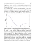
Fig. 7. Discharge profile for a SC under constant current.
The variables V
SCMAX
and C
SC
are indeed related by the number of cells n. The assumption is
that the capacitors will never be charged above the combined maximum voltage rating of all
the cells. Thus, we can introduce this relationship with the following equations,
n
C
C
nVV
SCcell
SC
SCcell
SCMAX
(11)
Generally, V
SCMIN
is chosen as V
SCMAX
/2, from (6), resulting in 75% of the energy being
utilized from the full-of-charge (
SOC
1
= 100%). In applications where high currents are
drawn, the effect of the
R
ESR
has to be taken into account. The energy dissipated W
loss
in the
R
ESR
, as well as in the cabling, and connectors could result in an under-sizing of the number
of capacitors required. For this reason, knowing SC current from (6), one can theoretically
calculate these losses as,
SCMIN
SCNOM
MINESRSCESR
t
0
2
C
loss
V
V
lnCRPdRiW
d
(12)
To calculate the required capacitance C
SC
, one can rewrite (6) as,
loss
SC
2
SCMIN
2
SCMAXSCMIN
WtPVVC
2
1
(13)
From (6) and (13), one obtains
tP
W
1CC
SC
loss
SCMINSC
(14)
where X is the energy ratio.
From the equations above, an iterative method is needed in order to get the desired
optimum value.
1
State Of Charge
Passivity-BasedControlandSlidingModeControl
appliedtoElectricVehiclesbasedonFuelCells,SupercapacitorsandBatteriesontheDCLink 115
C. State of the art and potential application
Developed at the end of the seventies for signal applications (for memory back-up for
example), SCs had at that time a capacitance of some farads and a specific energy of about
0.5 Wh.kg
-1
.
Fig. 8. Comparison between capacitors, supercapacitors, batteries and Fuel cell
High power SCs appear during the nineties and bring high power applications components
with capacitance of thousand of farads and specific energy and power of several Wh.kg
-1
and kW.kg
-1
.
In the energy-power plan, electric double layers SCs are situated between accumulators and
traditional capacitors.
Then these components can carry out two main functions:
- the function "source of energy", where SCs replace electrochemical accumulators, the
main interest being an increase in reliability,
- the function "source of power", for which SCs come in complement with accumulators
(or any other source limited in power), for a decrease in volume and weight of the whole
system.
2.3. State of the art of battery in electric vehicles
An electric vehicle (EV) is a vehicle that runs on electricity, unlike the conventional vehicles
on road today which are major consumers of fossil fuels like gasoline. This electricity can be
either produced outside the vehicle and stored in a battery or produced on board with the
help of FC’s.
The development of EV’s started as early as 1830’s when the first electric carriage was
invented by Robert Andersen of Scotland, which appears to be appalling, as it even precedes
the invention of the internal combustion engine (ICE) based on gasoline or diesel which is
prevalent today. The development of EV’s was discontinued as they were not very
convenient and efficient to use as they were very heavy and took a long time to recharge.
This led to the development of gasoline based vehicles as the one pound of gasoline gave
equal energy as a hundred pounds of batteries and it was relatively much easier to refuel
and use gazoline. However, we today face a rapid depletion of fossil fuel and a major
concern over the noxious green house gases their combustion releases into the atmosphere
causing long term global crisis like climatic changes and global warming. These concerns
EnergyManagement116
are shifting the focus back to development of automotive vehicles which use alternative
fuels for operations. The development of such vehicles has become imperative not only for
the scientists but also for the governments around the globe as can be substantiated by the
Kyoto Protocol which has a total of 183 countries ratifying it (As on January 2009).
A. Batteries technologies
A battery is a device which converts chemical energy directly into electricity. It is an
electrochemical galvanic cell or a combination of such cells which is capable of storing
chemical energy. The first battery was invented by Alessandro Volta in the form of a voltaic
pile in the 1800’s. Batteries can be classified as primary batteries, which once used, cannot
be recharged again, and secondary batteries, which can be subjected to repeated use as they
are capable of recharging by providing external electric current. Secondary batteries are
more desirable for the use in vehicles, and in particular traction batteries are most
commonly used by EV manufacturers. Traction batteries include Lead Acid type, Nickel and
Cadmium, Lithium ion/polymer , Sodium and Nickel Chloride, Nickel and Zinc.
Lead
Acid
Ni - Cd Ni - MH Li – Ion
Li -
polymer
Na -
NiCl
2
Objectives
Specific
Energy
(Wh/Kg)
35 – 40 55 70 – 90 125 155 80 200
Specific
Power
(W/Kg)
80 120 200 260 315 145 400
Energy
Density
(Wh/m
3
)
25 – 35 90 90 200 165 130 300
Cycle Life
(No. of
charging
cycles)
300 1000 600 + 600 + 600 600 1000
Table 1. Comparison between different baterries technologies.
The battery for electrical vehicles should ideally provide a high autonomy (i.e. the distance
covered by the vehicle for one complete discharge of the battery starting from its potential)
to the vehicle and have a high specific energy, specific power and energy density (i.e. light
weight, compact and capable of storing and supplying high amounts of energy and power
respectively). These batteries should also have a long life cycle (i.e. they should be able to
discharge to as near as it can be to being empty and recharge to full potential as many
number of times as possible) without showing any significant deterioration in the
performance and should recharge in minimum possible time. They should be able to operate
over a considerable range of temperature and should be safe to handle, recyclable with low
costs. Some of the commonly used batteries and their properties are summarized in the
Table 1.
Passivity-BasedControlandSlidingModeControl
appliedtoElectricVehiclesbasedonFuelCells,SupercapacitorsandBatteriesontheDCLink 117
B. Principle
A battery consists of one or more voltaic cell, each voltaic cell consists of two half-cells
which are connected in series by a conductive electrolyte containing anions (negatively
charged ions) and cations (positively charged ions). Each half-cell includes the electrolyte
and an electrode (anode or cathode). The electrode to which the anions migrate is called the
anode and the electrode to which cations migrate is called the cathode. The electrolyte
connecting these electrodes can be either a liquid or a solid allowing the mobility of ions.
In the redox reaction that powers the battery, reduction (addition of electrons) occurs to
cations at the cathode, while oxidation (removal of electrons) occurs to anions at the anode.
Many cells use two half-cells with different electrolytes. In that case each half-cell is
enclosed in a container, and a separator that is porous to ions but not the bulk of the
electrolytes prevents mixing. The figure 10 shows the structure of the structure of Lithium–
Ion battery using a separator to differentiate between compartments of the same cell
utilizing two respectively different electrolytes
Each half cell has an electromotive force (or emf), determined by its ability to drive electric
current from the interior to the exterior of the cell. The net emf of the battery is the
difference between the emfs of its half-cells. Thus, if the electrodes have emfs
E
1
and E
2
, then
the net emf is
E
cell
= E
2
- E
1
. Therefore, the net emf is the difference between the reduction
potentials of the half-cell reactions.
The electrical driving force or
∆V
Bat
across the terminals of a battery is known as the terminal
voltage and is measured in volts. The terminal voltage of a battery that is neither charging
nor discharging is called the open circuit voltage and equals the emf of the battery.
An ideal battery has negligible internal resistance, so it would maintain a constant terminal
voltage until exhausted, then dropping to zero. If such a battery maintained 1.5 volts and
stored a charge of one Coulomb then on complete discharge it would perform 1.5 Joule of
work.
Work done by battery (W) = - Charge X Potential Difference
(15)
ElectronsMoles
ElectronsMole
Coulomb
eargCh
(16)
nFEcellW
(17)
Where
n is the number of moles of electrons taking part in redox, F = 96485 coulomb/mole
is the Faraday’s constant i.e. the charge carried by one mole of electrons.
The open circuit voltage,
E
cell
can be assumed to be equal to the maximum voltage that can
be maintained across the battery terminals. This leads us to equating this work done to the
Gibb’s free energy of the system (which is the maximum work that can be done by the
system)
nFEcellmaxWG
(18)
EnergyManagement118
Fig. 9. Showing the apparatus and reactions for a simple galvanic Electrochemical Cell
Fig. 10. Structure of Lithium-Ion Battery
C. Model of Battery
Non Idealities in Batteries: Electrochemical batteries are of great importance in many
electrical systems because the chemical energy stored inside them can be converted into
electrical energy and delivered to electrical systems, whenever and wherever energy is
needed. A battery cell is characterized by the open-circuit potential (
V
OC
), i.e. the initial
potential of a fully charged cell under no-load conditions, and the cut-off potential (
V
cut
) at
which the cell is considered discharged. The electrical current obtained from a cell results
from electrochemical reactions occurring at the electrode-electrolyte interface. There are two
important effects which make battery performance more sensitive to the discharge profile:
- Rate Capacity Effect: At zero current, the concentration of active species in the cell is
uniform at the electrode-electrolyte interface. As the current density increases the
concentration deviates from the concentration exhibited at zero current and state of charge
as well as voltage decrease (Rao et al., 2005)
- Recovery Effect: If the cell is allowed to relax intermittently while discharging, the voltage
gets replenished due to the diffusion of active species thereby giving it more life (Rao et al.,
2005)
Passivity-BasedControlandSlidingModeControl
appliedtoElectricVehiclesbasedonFuelCells,SupercapacitorsandBatteriesontheDCLink 119
D. Equivalent Electrical Circuit of Battery
Many electrical equivalent circuits of battery are found in literature. (Chen at al., 2006)
presents an overview of some much utilized circuits to model the steady and transient
behavior of a battery. The Thevenin’s circuit is one of the most basic circuits used to study
the transient behavior of battery is shown in figure 11.
Fig. 11. Thevenin’s model
It uses a series resistor (R
series
) and an RC parallel network (R
transient
and C
transient
) to predict
the response of the battery to transient load events at a particular state of charge by
assuming a constant open circuit voltage [V
oc
(SOC)] is maintained. This assumption
unfortunately does not help us analyze the steady-state as well as runtime variations in the
battery voltage. The improvements in this model are done by adding more components in
this circuit to predict the steady-state and runtime response. For example, (Salameh at al.,
1992) uses a variable capacitor instead of V
oc
(SOC) to represent nonlinear open circuit
voltage and SOC, which complicates the capacitor parameter.
Fig. 12. Circuit showing battery emf and internal resistance R
internal
However, in our study we are mainly concerned with the recharging of this battery which
occurs while breaking. The SC coupled with the battery accumulates high amount of charge
when breaks are applied and this charge is then utilized to recharge the battery. Therefore,
the design of the battery is kept to a simple linear model which takes into account the
internal resistance (
R
internal
) of the battery and assumes the emf to be constant throughout
the process (Figure. 12).
EnergyManagement120
3. Control of the Electric Vehicles based on FC, SCs
and Batteries on the DC Link
3.1 Structure of the hybrid source
As shown in Fig. 13 the studied system comprises a DC link directly supplied by batteries, a
PEMFC connected to the DC link by means of a Boost converter, and a supercapacitive
storage device connected to the DC link through a current reversible DC-DC converter. The
function of FC and the batteries is to supply mean power to the load, whereas the storage
device is used as a power source: it manages load power peaks during acceleration and
braking.
The aim is to have a constant DC voltage and the challenge is to maintain a constant power
working mode for the main sources (batteries and FC).
3.2. Problem formulation
The main objectives of the proposed study are:
- To compare two control techniques of the hybrid source by controlling the two DC-DC
converters. The first is based on passivity control by using voltage control (on FC and
current control for SC), and the second is based on sliding mode control by using current
controller.
- To maintain a constant mean energy delivered by the FC, without a significant power
peak, and to ensure the transient power is supplied by the SCs.
- To recover energy through the charge of the SC.
After system modelling, equilibrium points are computed in order to ensure the desired
behaviour of the system. When steady state is reached, the load has to be supplied only by
the FC source. So the controller has to maintain the DC bus voltage to a constant value and
the SCs current has to be cancelled. During transient, the power delivered by the DC source
has to be the more constant as possible (without a significant power peak), so the SCs
deliver the transient power to the load. If the load provides current, the SCs recover its
energy.
At equilibrium, the SC has to be charged and the current has to be equal to zero.
I
DL
C
S
I
FC
V
FC
FC
T
FC
L
DL
L
FC
I
b
E
B
V
DL
C
DL
V
SC
I
L
I
SC
T
SC
L
SC
r
B
SC
V
S
T
SC
Load
R
L
L
L
E
L
I
DL
C
S
I
FC
V
FC
FC
T
FC
L
DL
L
FC
I
b
E
B
V
DL
C
DL
V
SC
I
L
I
SC
T
SC
L
SC
r
B
SC
V
S
T
SC
Load
R
L
L
L
E
L
Load
R
L
L
L
E
L
Fig. 13. Structure of the hybrid source
Passivity-BasedControlandSlidingModeControl
appliedtoElectricVehiclesbasedonFuelCells,SupercapacitorsandBatteriesontheDCLink 121
3.3 Port Controlled Hamiltonian System
PCH systems were introduced by van der Schaft and Maschke in the early nineties, and
have since grown to become a large field of interest in the research of electrical, mechanical
and electro-mechanical systems. A recent and very interesting approach in PBC is the
Interconnection and Damping Assignment (IDA-PBC) method, which is a general way of
stabilizing a large class of physical systems) (Ortega et al. 2002) (Becherif et al., 2005).
A. Equations of the system
The overall model of the hybrid system is written in a state space equation by choosing the
following state space vector:
T
LSCSCDLDLFCS
T
7654321
IIVIVIV
xxxxxxxx
(19)
The output voltage of a single cell
V
FC
can be defined as the result of the following expression:
Lim
nFC
nFCm
0
nFC
0FC
i
ii
1logB)ii(R
i
ii
logAEV
(20)
where
E is the thermodynamic potential of the cell representing its reversible voltage, i
FC
is
the delivered current, i
o
is the exchange current, A is the slope of the Tafel line, i
Lim
is the
limiting current, B is the constant in the mass transfer, i
n
is the internal current and R
m
is the
membrane and contact resistances. Hence V
FC
= f(i
FC
).
The fourth term represents the voltage drop resulting from the concentration or mass
transportation of the reacting gases.
In equation (20), the first term represents the FC open circuit voltage, while the three last
terms represent reductions in this voltage to supply the useful voltage of the cell
V
FC
, for a
certain operating condition. Each of the terms can be calculated by the following equations,
The control vector is:
T
SCFC
T
21
U1,U1,
or
T
SCFC
U,UU
(21)
With V
FC
=V
FC
(x
2
) given in (Larminie & Dicks, 2000). In the sequel, V
FC
will be considered as
a measured disturbance, and from physical consideration, it comes that V
FC
[0; V
d
[.
EnergyManagement122
B. Equilibrium
After simple calculations the equilibrium vector is:
T
L
d
SC
B
d
B
L
d
d
B
d
B
L
d
FC
d
d
T
7654321
R
V
,0,0tV,
r
VE
R
V
,V,
r
VE
R
V
V
V
,V
x,x,x,x,x,x,xx
(22)
where
d
V is the desired DC link voltage. An implicit purpose of the proposed structure
shown in Fig.13 is to recover energy to charge the SC. Hence, the desired
voltage
0tVVx
SCSC5
=Constante.
T
d
5
d
FC
T
21
V
x
,
V
V
,
(23)
Or
T
d
5
d
FC
T
SCFC
V
x
1,
V
V
1U,UU
(24)
The natural energy function of the system is:
Qxx
2
1
H
T
(25)
where
LSCSCDLDLFcS
L;L;C;L;C;L;CdiagQ
is a diagonal matrix.
C. Port-Controlled Hamiltonian representation of the system
In the following, a closed loop PCH representation is given. The desired closed loop energy
function is:
xQxH
T
d
~~
2
1
(26)
Where
xxx
~
is the new state space defining the error between the state
x
and its
equilibrium value
x
.
The PCH form of the studied system with the new variable
x
~
as a function of the gradient
of the desired energy (26) is:
,xAH,x
~
i
d
21
(27)
Passivity-BasedControlandSlidingModeControl
appliedtoElectricVehiclesbasedonFuelCells,SupercapacitorsandBatteriesontheDCLink 123
With
2
2
2
2
1
1
21
000
1
00
00
1
000
0
1
00000
0000
1
0
1
1
0
11
00
000000
000
1
00
,
L
L
LDL
SCSCSCDL
SCSC
DLDLDLS
LDLSCDLDLDL
BDL
FCS
DLSFCS
L
R
LC
LCLC
LC
LCLC
LCLCLC
rC
LC
LCLC
(28)
And
7L
6SC
5SC
4DL
3DL
2FC
1S
d
x
~
L
x
~
L
x
~
C
x
~
L
x
~
C
x
~
L
x
~
C
H
(29)
0
xx
L
1
0
0
0
xV
L
1
xxC
,xA
325
SC
11FC
FC
214S
i
(30)
Where
21
T
21
,,
(31)
is a skew symmetric matrix defining the interconnection between the state space and
0
T
is a symmetric positive semi definite matrix defining the damping of the
system.
With
r is a design parameter, the following control laws are proposed:
62211
x
~
rand
(32)
EnergyManagement124
Proposition 1: The origin of the closed loop PCH system (27), with the control laws (32) and
(23) with the radially unbounded energy function (26), is globally stable.
Proof: The closed loop dynamic of the PCH system (27) with the laws (32) and (23) with the
radially unbounded energy function (26) is:
d
21
H,x
~
(33)
where
0;;0;0;
1
;0;0
222
T
L
L
SC
d
BDL
L
R
L
rV
rC
diag
(34)
The derivative of the desired energy function (26) along the trajectory of (33) is:
0HHx
~
HH
d
T
d
T
dd
(35)
3.4 Sliding mode control of the system
Due to the weak request on the FC, a classical PI controller is adapted for the boost
converter. Because of the fast response in the transient power and the possibility to work
with a variable or a constant frequency, a non-linear sliding mode control (ayad et al, 2007)
which allows management of the charge and discharge of the SC tank is chosen for the DC-
DC bidirectional SC converter.
The current supplied by the FC is limited to an interval [I
MIN
, I
MAX
]. Within this interval, the
FC boost ensures the regulation of this current to its reference. But, as soon as the load
current is greater than I
MAX
or lower than I
MIN
, the boost becomes unable to regulate the
desired current. The lacking or excess current is then provided or absorbed by the storage
device, hence the DC link current is kept equal to its reference level. Consequently, three
modes can be defined to optimize the function of the hybrid source:
- The normal mode, for which the load current is within the interval [I
MIN
, I
MAX
]. In this
mode, the boost ensures the regulation of the DC link current, and the control of the
bidirectional SC converter leads to the charge or the discharge of SC up to a reference
voltage level V
SCREF
,
- The discharge mode, for which the load current is greater than I
MAX
. The current reference
of the boost is then saturated to I
MAX
, and the DC-DC converter ensures the regulation of the
DC link current by supplying the lacking current through the SC discharge,
- The recovery mode, for which the load current is lower than I
MIN
. The power reference of
the controlled rectifier is then saturated to I
MIN
and the DC-DC converter ensures the
regulation of the DC link current by absorbing the excess current through the SC charge.
A. DC-DC Fuel Cell converter control principle
The FC current reference
*
FC
I
is generated by means of a PI current loop control on a DC link
current and load current. The switching device is controlled by a hysterisis comparator.
t
0
DLLIDLLp
*
FC
dtIIkIIkI
(36)
where k
p
and k
i
are the proportional and integral gains.
Passivity-BasedControlandSlidingModeControl
appliedtoElectricVehiclesbasedonFuelCells,SupercapacitorsandBatteriesontheDCLink 125
P.I
corrector
FC
U
+
_
FC
I
*
FC
I
+
_
P.I
corrector
FC
U
+
_
+
_
FC
I
*
FC
I
+
_
+
_
I
L
I
DL
P.I
corrector
FC
U
+
_
FC
I
*
FC
I
+
_
P.I
corrector
FC
U
+
_
+
_
FC
I
*
FC
I
+
_
+
_
I
L
I
DL
Fig. 14. Control of the FC converter
B. DC-DC Supercapacitors converter control principle
To ensure proper function for the three modes, we use a sliding mode control for the
bidirectional SC converter. Thus we define a sliding surface S as a function of the DC link
current I
DL
, the load current I
L
, the SC voltage V
SC
, its reference
*
SC
V
and the SC current I
SC
:
IIkIIS
SCCLDL
(37)
with
t
0
*
SCSCis
*
SCSCps
dtVVkVVkI
(38)
With, k
ps
and k
is
are the proportional and integral gains.
When S < 0, the lower
T
SC
=1 in Fig.14 is switched on, and the upper
0T
SC
is switched
off. When S > 0, the upper
1T
SC
is switched on and the lower
T
SC
=0 is switched off.
The FC PI controller ensures that I
DL
tracks I
L
. The SC PI controller ensures that V
SC
tracks its
reference
*
SC
V
.
k
C
is the coefficient of proportionality, which ensures that the sliding surface equals zero by
tracking the SC currents to its reference I when the FC controller cannot ensure I
DL
tracks I
L
.
In steady state conditions, the FC converter ensures that the first term of the sliding surface
is zero, and the integral term of equation (38) implies that
*
SCSC
VV
. Then, imposing S = 0
leads to I
SC
= 0, as far as the boost converter output current I
DL
is not limited so that the
storage element supplies energy only during power transient and I
DL
limitation.
The general system of the DC link and the DC-DC SC converter equations can be written as:
CBUAXX
(39)
With
T
SCSCDL
IVIVX
EnergyManagement126
And
0kC/k0
00C/10
0L/1L/rL/1
00C/1C.r1
A
isSCps
SC
SCSCSCSC
DLDLB
T
SC
DL
DL
SC
00
L
V
C
I
B
,
T
DL
LDL
000
C
)II(
T
*
SCis
DLB
B
Vk00
)Cr(
E
C
,
SC
UU
If we denote
CC
k0k0G
(40)
the sliding surface is then given by
GXCS
DL
(41)
In order to set the system dynamics, we define the reaching law
SKsignSS
(42)
with
0K
if
S
and
nK
if
S
(43)
The linear term
XS imposes the dynamics inside the error bandwidth. The choice of a
high value of (
2f
C
) ensures a small static error when S . The non-linear term
SKsign
permits to reject perturbation effects (uncertainty of the model, variations of the
working conditions…). This term allows compensation high values of error
S due to
the above mentioned perturbations. The choice of a small value of leads to high current
ripple (chattering effect) but the static error remains small. A high value of forces a
reduction in the value of to ensure the stability of the system and leads to a higher static
error.
Once the parameters (, K, ) of the reaching law are determined, it is possible to calculate
the continuous equivalent control, which allows the state trajectory on the sliding surface to
be maintained. Using Equations (39), (41) and (42), we find:
DL
1
SCeq
C)S(KsignGXGCGAXGBU
(44)
(37) and (39) give the equation:
GGBBGAGBBAA
11
eq
(45)
This equation allows the determination of the poles of the system during the sliding motion
as a function of and k
C
. The parameters k
is
and k
ps
are then determined by solving S = 0.
Passivity-BasedControlandSlidingModeControl
appliedtoElectricVehiclesbasedonFuelCells,SupercapacitorsandBatteriesontheDCLink 127
This equation is justified by the fact that the sliding surface dynamic is much greater than
the SC voltage variation.
C. Stability
Consider the following Lyapunov function:
2
S
2
1
V
(46)
Where
, S is the sliding surface.
The derivative of the Lyapunov function along the trajectory of (42) in the closed loop with
the control (44) gives:
0)S(KSsignSSSV
2
(47)
With
0K,
Hence, the origin of the closed loop of the system (39) with the control (44) and the sliding
surface (41) is asymptotically stable.
3.5 Simulation results of the hybrid source control
The whole system has been implemented in MATLAB-SIMULINK with the following
parameters associated to the hybrid sources:
- FC parameters: P
MAX
= 400 W.
- DC link parameters: V
DL
= 24 V.
- SC parameters: C
SC
= 3500/6 F, V15V
*
SC
.
The results presented in this section have been carried out by connecting the hybrid source
to a "R, L and E
L
" load.
A. Sliding mode control applied to the hybrid source
Figures 15, 16 and 17 present the behaviour of currents I
DL
, I
DL
, I
SC
, I
B
and the DC link
voltage V
DL
for transient responses obtained for a transition from the normal mode to the
discharge mode by using sliding mode control. The test is performed by changing sharply
the e.m.f load voltage E
L
in the interval of t[0.5 s, 1.5 s]. The load current I
L
changes from
16.8 A to 25 A. The current load I
L
= 16.8 A corresponds to a normal mode and the current
load I
L
= 25 A to a discharge mode.
At the starting of the system, only the FC provides the mean power to the load. The storage
device current reference is equal to zero, we are in normal mode. In the transient state, the
load current I
L
became greater then the DC link current I
DL
. The storage device current
reference became positive thanks to control function which compensate this positive value
by the difference between the SC voltage and its reference. We are in discharging mode.
After the load variation (t > 1.5 s), the current in the DC link became equal to the load
current. The SC current I
SC
became null. We have a small variation in the batteries currents.
EnergyManagement128
I
L
I
DL
Fig. 15. Load and DC link currents
I
SC
I
B
Fig. 16. SC and batteries currents
Fig. 17. DC link voltage
Passivity-BasedControlandSlidingModeControl
appliedtoElectricVehiclesbasedonFuelCells,SupercapacitorsandBatteriesontheDCLink 129
B. Passivity Based Control applied to the hybrid source
Figure 18 shows the FC voltage and current. Figure 19 presents the SC voltage and current
response. The SC supply power to the load in the transient and in the steady state no power
or energy is extracted since the current x
6
= I
SC
is null.
The positive sens of I
SC
means that the SCs supply the load and the negative one
corresponds to the recover of energy from the FC to the SC. Figure 20 presents the batteries
voltage and its current. Figure 21 presents the response of the system to changes in the load
current I
L
. The DC Bus voltage tracks well the reference, i.e. very low overshoot and no
steady state error are observed. It can be seen from this figure that the system with the
proposed controller is robust towards load resistance changes. Figure 22 shows the FC Boost
controller, the SC bidirectional converter controller and the changes in the Load resistance
RL. U
SC
and U
FC
are in the set [0; 1].
V
FC
(V)
I
FC
(A)
V
FC
(V)
I
FC
(A)
Fig. 18. FC voltage and FC current
V
SC
(V)
I
SC
(A)
V
SC
(V)
I
SC
(A)
Fig. 19. SC voltage and SC current
EnergyManagement130
V
B
(V)
I
b
(A)
V
B
(V)
I
b
(A)
Fig. 20. Batteries voltage and batteries current
V
DL
, V
d
(V)
I
L
(A)
V
DL
, V
d
(V)
I
L
(A)
Fig.21. DC link voltage and load current
U
FC
R
L
()
U
SC
U
FC
R
L
()
U
SC
Fig. 22. (a) FC Boost control. (b) SC DC-DC (c) Load resistance change
Passivity-BasedControlandSlidingModeControl
appliedtoElectricVehiclesbasedonFuelCells,SupercapacitorsandBatteriesontheDCLink 131
4. Conclusion
In this paper, control principles of a hybrid DC source have been presented. This source
uses the fuel cell as mean power source, SCs as auxiliary transient power source and
batteries on the DC link.
Passivity Based Control and Sliding Mode Control principles have been applied and
validated by simulation results. Include main findings and highlight the positive points of
the simulation results and the possibility of applying this new concept in Fuel Cell
applications.
PCH structure of the overall system is given exhibiting important physical properties in
terms of variable interconnection and damping of the system. The problem of the DC Bus
Voltage control is solved using simple linear controllers based on an IDA-PBC approach.
With the sliding mode principle control, we have a robustness control. But the sliding
surface is generated in function of multiple variables: DC link voltage, SCs current and
voltage.
With PBC, only two measures are needed to achieve the control aims of this complex system
(the FC Voltage and the SC current), while for the Sliding mode control we need to achieve
the control aims of this complex system (the FC Voltage, the SC current, the SC voltage, load
and DC link currents). The sliding mode is faster in terms of response to a set point change
or disruption.
The PBC control laws are completely independent from the system’s parameters, and then
this controller is robust towards the parameter variation. The Sliding mode controller is
function of the system parameter and is therefore sensitive to there changes.
The PBC control laws are very simple to realize and produce continuous behavior while the
sliding mode control is more complicated (realization of the surface and the control laws)
and introduce nonlinearities by commutation.
Global Stability proofs are given and encouraging simulation results has been obtained.
Many benefits can be expected from the proposed structure such that supplying and
absorbing the power picks by using SC which also allows recovering energy.
5. References
Kishinevsky, Y. & Zelingher, S. (2003). Coming clean with fuel cells, IEEE Power & Energy
Magazine, vol. 1, issue: 6, Nov Dec. 2003, pp. 20-25.
Larminie, J. & Dicks, A. (2000). Fuel cell systems explained, Wiley, 2000.
Pischinger, S.; Schönfelder, C. & Ogrzewalla, J. (2006). Analysis of dynamic requirements for
fuel cell systems for vehicle applications, J. Power Sources, vol. 154, no. 2, pp. 420-
427, March 2006.
Moore, R. M.; Hauer, K. H.; Ramaswamy, S. & Cunningham, J. M. (2006). Energy utilization
and efficiency analysis for hydrogen fuel cell vehicles, J. Power Sources, 2006.
Corbo, P.; Corcione, F. E.; Migliardini, F. & Veneri, O. (2006). Experimental assessment of
energy-management strategies in fuel-cell propulsion systems, J. Power Sources,
2006.
Rufer, A.; Hotellier, D. & Barrade, P. (2004). A Supercapacitor-Based Energy-Storage
Substation for Voltage - Compensation in Weak Transportation Networks,” IEEE
Trans. Power Delivery, vol. 19, no. 2, April 2004, pp. 629-636.
EnergyManagement132
Thounthong, P.; Raël, S. & Davat, B. (2007). A new control strategy of fuel cell and
supercapacitors association for distributed generation system, IEEE Trans. Ind.
Electron, Volume 54, Issue 6, Dec. 2007 Page(s): 3225 – 3233
Corrêa, J. M.; Farret, F. A.; Gomes, J. R. & Simões, M. G. (2003). Simulation of fuel-cell stacks
using a computer-controlled power rectifier with the purposes of actual high-
power injection applications, IEEE Trans. Ind. App., vol. 39, no. 4, pp. 1136-1142,
July/Aug. 2003.
Benziger, J. B.; Satterfield, M. B.; Hogarth, W. H. J.; Nehlsen, J. P. & Kevrekidis; I. G. (2006).
The power performance curve for engineering analysis of fuel cells, J. Power
Sources, 2006.
Granovskii, M.; Dincer, I. & Rosen, M. A. (2006). Environmental and economic aspects of
hydrogen production and utilization in fuel cell vehicles, J. Power Sources, vol. 157,
pp. 411-421, June 19, 2006
Ortega, R.; van der Schaft, A.J.; Maschke, B. & Escobar, G. (2002). Interconnection and
damping assignment passivity–based control of port–controlled hamiltonian
systems, Automatica, vol.38(4), pp.585–596, 2002.
Becherif, M. & Mendes, E. (2006). Stability and robustness of Disturbed- Port Controlled
Hamiltonian system with Dissipation, 16th IFAC World Congress, Prague, 2005.
Becherif, M. & Ayad, M. Y. (2006). Modelling and Passivity-Based Control of Hybrid
Sources: Fuel cell and Supercapacitors,
In 41st IEEE-IAS 2006, USA.
Ayad, M. Y.; Gualous, A.; Cirrincione, M. & Miraoui, A. (2007). Study And Realization Of A
Power Source Using Supercapacitors Matrix and Fuel cell, in Proc. 2nd European
Ele-Drive Transportation Conference EET-2007 - Brussels, 30th May - 1st June 2007
Ayad, M. Y.; Pierfederici, S.; Raël, S. & Davat, B. (2007). Voltage Regulated Hybrid DC
Source using supercapacitors, Energy Conversion and Management, Volume 48,
Issue 7, July 2007, Pages 2196-2202.
Belhachemi, F.; Rael, S. & Davat, B. (2000). A Physical based model of power elctric double
layer supercapacitors, IAS 2000, 35th IEEE Industry Applications Conference,
Rome, 8-12 October
Rao, V.; Singhal, G.; Kumar, A. & Navet, N. (2005). Model for Embedded Systems Battery,
Proceedings of the 18th International Conference on VLSI Design held jointly with
4th International Conference on Embedded Systems Design (IEEE-VLSID’05), 2005.
Chen, M.; Gabriel, A.; Rincon-Mora. (2006). Accurate Electrical Battery Model Capable of
Predicting Runtime and
I–V Performance. . IEEE Trans. Energy Convers, Vol. 21,
No.2, pp.504-511 June 2006.
Salameh, Z.M.; Casacca, M.A. & Lynch, W.A. (1992). A mathematical model for lead-acid
batteries,
IEEE Trans. Energy Convers., vol. 7, no. 1, pp. 93–98, Mar. 1992.