Báo cáo hóa học: " Au Nanoparticles as Interfacial Layer for CdS Quantum Dot-sensitized Solar Cells" pdf
Bạn đang xem bản rút gọn của tài liệu. Xem và tải ngay bản đầy đủ của tài liệu tại đây (433.44 KB, 6 trang )
NANO EXPRESS
Au Nanoparticles as Interfacial Layer for CdS Quantum
Dot-sensitized Solar Cells
Guang Zhu
•
Fengfang Su
•
Tian Lv
•
Likun Pan
•
Zhuo Sun
Received: 26 May 2010 / Accepted: 15 July 2010 / Published online: 28 July 2010
Ó The Author(s) 2010. This article is published with open access at Springerlink.com
Abstract Quantum dot-sensitized solar cells based on
fluorine-doped tin oxide (FTO)/Au/TiO
2
/CdS photoanode
and polysulfide electrolyte are fabricated. Au nanoparticles
(NPs) as interfacial layer between FTO and TiO
2
layer are
dip-coated on FTO surface. The structure, morphology and
impedance of the photoanodes and the photovoltaic per-
formance of the cells are investigated. A power conversion
efficiency of 1.62% has been obtained for FTO/Au/TiO
2
/
CdS cell, which is about 88% higher than that for FTO/
TiO
2
/CdS cell (0.86%). The easier transport of excited
electron and the suppression of charge recombination in the
photoanode due to the introduction of Au NP layer should
be responsible for the performance enhancement of the
cell.
Keywords Quantum dot-sensitized solar cell Á
Gold nanoparticles Á Interfacial layer
Introduction
Quantum dot-sensitized solar cells (QDSSCs) are consid-
ered as a promising candidate for the development of next
generation solar cells because they can be fabricated by
simple and low-cost techniques [1, 2]. The development of
nanotechnogy, especially the synthesis and application of
nanomaterials [3–8], facilitates the progress of QDSSCs
and enables them to receive more and more interests.
Currently, the efforts on improving the performance of
QDSSCs have mainly been focused on fundamental issues,
such as improved understanding of device physics [9],
optimization of device structure by advanced processing
methods [10, 11] and development of high-performance
materials [12–16]. These combined efforts have led to very
encouraging power conversion efficiency of 4.22% [17].
However, such efficiency is far away for the practical
applications. As a result, further exploration on the opti-
mization of QDSSC performance is necessary.
For QDSSCs, electrons generated by the quantum dots
have to pass through numerous grain boundaries and the
interfaces between conductive substrate and semiconductor
oxide layer to reach the conductive substrate via conduc-
tion band of semiconductor oxide. Therefore, the control of
the charge carrier transportation at interfaces is one of the
most challenging issues in the improvement of QDSSCs.
Lee et al. [18, 19] reported the modification of QDSSCs by
using single-walled carbon nanotubes (SWCNTs) on
indium-doped tin oxide electrodes. The power conversion
efficiency of the cell was increased by 50.0% for CdS
QDSSCs and 35.6% for PbS QDSSCs due to the improved
charge-collecting efficiency and reduced recombination in
the presence of SWCNTs. Kim et al. [20] used graphene-
TiO
2
composite as an interfacial layer between fluorine-
doped tin oxide (FTO) layer and nanocrystalline TiO
2
for
dye-sensitized solar cells. The introduction of graphene-
TiO
2
increased the efficiency from 4.8 to 5.26% due to the
retardation of the back-transport reaction resulting from the
direct contact of the electrolyte with the FTO substrate.
As a noble metal, nanosized Au exhibits unusual electric
and optical properties as well as high chemical stability
[21–23]. Therefore, Au can be considered as an interfacial
layer between active layer and conductive substrate to
improve the performance of cells. Kouskoussa et al.
[24, 25] employed a Au ultrathin layer between FTO or
G. Zhu Á F. Su Á T. Lv Á L. Pan (&) Á Z. Sun
Engineering Research Center for Nanophotonics & Advanced
Instrument, Ministry of Education, Department of Physics,
East China Normal University, Shanghai, China
e-mail:
123
Nanoscale Res Lett (2010) 5:1749–1754
DOI 10.1007/s11671-010-9705-z
aluminum-doped zinc oxide anode and organic electron
donor layer to improve the interface resistance of organic
solar cells. A higher conversion efficiency of cells had been
achieved due to better hole collection efficiency due to the
introduction of Au ultrathin layer. However, using nano-
sized Au as interfacial layer in the photoanode for
improving the QDSSC performance has seldom been
reported despite their expected potential to enhance the
solar energy conversion efficiency due to favorable charge
collection.
In this work, we reported CdS QDSSCs using Au
nanoparticles (NPs) as interfacial layer between FTO and
TiO
2
layer. A large improvement in the efficiency up to
1.62% is achieved when compared with 0.86% for the
QDSSC without Au NP interfacial layer. The easier
transport of excited electron and the suppression of charge
recombination in the photoanode due to the introduction of
Au NP layer should be responsible for the performance
enhancement of the cell.
Experimental
FTO glass (resistivity: 14 X/h, Nippon Sheet Glass, Japan)
was used as the substrate for nanocrystalline TiO
2
(P25,
Degussa) electrodes. Cadmium nitrate [Cd(NO
3
)
2
], sodium
sulfide [Na
2
S], methanol [CH
3
OH] and ethanol [CH
3
CH
2
OH] (analytical grade purity) were purchased from
Shanghai Chemical Reagents Co. Ltd. and were used
without further purification.
The Au NP colloid solution was prepared by the mod-
ified tannic acid/citrate method using chlorauric acid tri-
hydrate, sodium citrate tribasic dehydrate, potassium
carbonate anhydrous and tannic acid [26]. The concentra-
tion of the Au NPs is about 0.3 mM.
Prior to the fabrication of TiO
2
film, FTO glass was
ultrasonically cleaned sequentially in HCl, acetone, ethanol
and water each for 30 min. After drying in the air, the FTO
glass was immersed in Au NP colloid solution at 70°C for
30 min. TiO
2
film was prepared by screen printing of TiO
2
paste on the FTO glass, followed by sintering at 500°C for
30 min. The thickness of TiO
2
layer was about 5 lm.
CdS deposition on the TiO
2
film was performed by
successive ionic layer adsorption and reaction (SILAR)
technique [27]. The film was dipped into an ethanol solu-
tion containing 0.33 M Cd(NO
3
)
2
for 30 s, rinsed with
ethanol and then dipped for another 30 s into a 0.5 M Na
2
S
methanol solution and rinsed again with methanol. The
two-step dipping procedure was considered to be one cycle.
It is known that the amount of CdS QDs assembled on the
photoanode increases with the number of SILAR cycles.
Too thin or too thick CdS layer is not beneficial to the
performance of QDSSCs and thus appropriate SILAR cycle
is very important [28, 29]. In our experiments, the best
performance of QDSSCs can be achieved for the pho-
toanode assembled with CdS in about 12 SILAR cycles.
Direct deposition of CdS on screen-printed TiO
2
(TiO
2
/
CdS) film without Au NP interfacial layer by SILAR
process with 12 cycles was also carried out for comparison.
The UV–vis transmittance spectra of FTO glass and
FTO glass with Au NPs (FTO/Au) were detected using a
UV–vis spectrophotometer (Hitachi U3900). The mor-
phology and structure of TiO
2
and TiO
2
/CdS films were
characterized by using a Hitachi S-4800 field emission
scanning electron microscopy (FESEM) and a JEOL-
2010 high-resolution transmission electron microscope
(HRTEM), respectively. Impedance spectroscopy (IS)
measurements [30–32] were carried out in dark conditions
at forward bias: 0–0.7 V, applying a 10 mV AC sinusoidal
signal over the constant applied bias with the frequency
ranging between 500 kHz and 0.1 Hz (Autolab, PGSTAT
302 N and FRA2 module).
The QDSSCs were fabricated in a sandwich structure
with TiO
2
film as photoanode and thin Au-sputtered FTO
glass as counter electrode. Water/methanol (3:7 by volume)
solution was used as a co-solvent of the polysulfide elec-
trolyte [29]. The electrolyte solution consists of 0.5 M
Na
2
S, 2 M S and 0.2 M KCl. The active area of the cell
was 0.25 cm
2
. Photocurrent–voltage measurement was
performed with a Keithley model 2440 Source Meter and a
Newport solar simulator system (equipped with a 1 kW
xenon arc lamp, Oriel) at one sun (AM 1.5G, 100
mWcm
-2
), which was calibrated with a reference Si ref-
erence solar cell (P/N 91150 V, Oriel). Incident photon to
current conversion efficiency (IPCE) was measured as a
function of wavelength from 300 to 800 nm using an Oriel
300 W xenon arc lamp and a lock-in amplifier M 70104
(Oriel) under monochromator illumination, which was
calibrated with a mono-crystalline silicon diode.
Results and Discussion
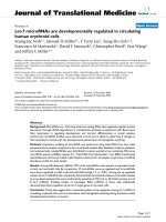
Figure 1a shows the low-magnification HRTEM image of
Au NPs. The size of Au NPs is mainly distributed from 3 to
8 nm (the inset of Fig. 1a). High-magnification HRTEM
image (Fig. 1b) shows that the Au NPs have a d-spacing of
0.236 nm corresponding to (111) lattice plane. The trans-
mittance spectra of FTO and FTO/Au are presented in
Fig. 1c. It can be seen that there is little transmittance
degradation (*1%) when FTO is coated with Au NPs,
which shall not affect the performance of cells.
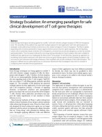
Figure 2a and b show FESEM images of TiO
2
and TiO
2
/
CdS films, respectively. The TiO
2
film is constructed by a
random agglomeration of tiny-sized TiO
2
nanocrystalline
particles. The porous structure of TiO
2
favors an easy
1750 Nanoscale Res Lett (2010) 5:1749–1754
123
penetration of electrolyte, as well as Cd and S precursors,
during deposition. When CdS is deposited onto TiO
2
film,
an apparent difference in the surface morphology is
observed. This result indicates that a great amount of CdS
QDs is assembled on the surface of TiO
2
film. Figure 2c
shows a low-magnification HRTEM image of TiO
2
/CdS
film. The larger size of the particles (about 30 nm) when
compared with pure P25 TiO
2
particles (about 20–25 nm)
indicating the surface of TiO
2
is coated with CdS by
SILAR processes. Figure 2d shows a high-magnification
HRTEM image of the interface region in TiO
2
/CdS film.
The larger crystallite is identified to be a TiO
2
NP. The
lattice spacing measured for this crystalline plane is
0.352 nm, corresponding to the (101) plane of anatase TiO
2
(JCPDS 21–1272). Around TiO
2
crystallite edge, fine
crystallites are observed. The crystallites connecting to the
TiO
2
have lattice fringes of 0.335 nm which is ascribed to
(111) plane of CdS (JCPDS 80-0019). Therefore, the
Fig. 1 a Low-magnification HRTEM image of Au NPs (Inset is the
size distribution histogram of Au NPs); b high-magnification HRTEM
image of Au NPs; c transmittance spectra of FTO and FTO/Au
Fig. 2 Surface morphologies of a TiO
2
and b TiO
2
/CdS films by
FESEM measurements; c Low-magnification and d high-magnifica-
tion HRTEM images of TiO
2
/CdS film
Nanoscale Res Lett (2010) 5:1749–1754 1751
123
HRTEM image confirms that CdS QDs are attached to the
surface of TiO
2
.
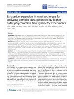
Figure 3 shows the I–V curves of the cells with and
without the Au NP interfacial layer (named as FTO/TiO
2
/
CdS and FTO/Au/TiO
2
/CdS cells). The open circuit
potential (V
oc
), short circuit current (I
sc
), fill factor (FF)
and conversion efficiency (g) of FTO/TiO
2
/CdS and
FTO/Au/TiO
2
/CdS cells are listed in Table 1. It can be
observed that the I
sc
,V
oc
and g have increased from
5.72 mAcm
-2
, 0.47 V and 0.86% for FTO/TiO
2
/CdS cell
to 7.11 mAcm
-2
, 0.56 V and 1.62% for FTO/Au/TiO
2
/CdS
cell, respectively, while FF increase somewhat. Figure 4
compares the IPCE spectra of FTO/TiO
2
/CdS and FTO/Au/
TiO
2
/CdS cells. The IPCE is defined as the number of
photogenerated charge carriers contributing to the current
per incident photon. The FTO/Au/TiO
2
/CdS cell shows a
typical spectral response of TiO
2
/CdS blend with a maxi-
mum IPCE of 41% at 440 nm, while for the FTO/TiO
2
/
CdS cell, the peak reaches 36% only. The insertion of Au
NP interfacial layer demonstrates a substantial enhance-
ment of *14% at 440 nm in the IPCE. This result also
indicates that Au NP layer facilitates the excited electron
transport from CdS to TiO
2
film.
The energy levels of FTO, Au, TiO
2
and CdS are
schematically shown in Fig. 5a. The conduction band of
TiO
2
is -4.2 eV (vs. vacuum) [33]. The work function of
Au is around -5.1 eV [34], lower than the one of FTO
(-4.2–4.4 eV) [35]. However, the contact between Au and
FTO can modify the Fermi level of FTO to a lower energy
and form a stepwise energy level between TiO
2
and FTO/
Au. Such a stepwise energy level built in the electrode is
advantageous to the electron transfer from TiO
2
to FTO via
Au NP layer. The easy electron transfer from TiO
2
to Au
NPs when small-sized Au NPs contact with TiO
2
to form a
nanoscale heterointerface has also been described by
Shibata et al. [36] and Kiyonaga et al. [37]. Figure 5b
shows a stepwise structure of energy level for efficient
transport of excited electrons in the electrode. The presence
of Au NP layer on FTO not only provides efficient elec-
tron-transfer route with enhanced charge collection which
contributes to the enhanced I
sc
[38] but also suppresses the
charge recombination by reducing back-transport reaction
between the electrolyte and FTO substrate which improves
the V
oc
[19]. As a result, the g of the FTO/Au/TiO
2
/CdS
cell is increased remarkably.
The easier transport of excited electron and the sup-
pression of charge recombination in the photoanode due to
the introduction of Au NP layer can be described well by
analyzing the impedance data of FTO/TiO
2
/CdS and FTO/
Au/TiO
2
/CdS cells. The obtained impedance spectra are
Fig. 3 I-V curves of FTO/TiO
2
/CdS and FTO/Au/TiO
2
/CdS cells
Table 1 Photovoltaic parameters of FTO/TiO
2
/CdS and FTO/Au/
TiO
2
/CdS cells
Electrode V
oc
(V) I
sc
(mA/cm
2
)FF g (%)
FTO/Au/TiO
2
/CdS 0.56 7.11 0.41 1.62
FTO/TiO
2
/CdS 0.47 5.72 0.38 0.86
Fig. 4 IPCE curves of FTO/TiO
2
/CdS and FTO/Au/TiO
2
/CdS cells
Fig. 5 a Schematic diagram of energy levels of FTO, Au, TiO
2
and
CdS; b stepwise structure of energy level for efficient transport of
excited electrons in the electrode
1752 Nanoscale Res Lett (2010) 5:1749–1754
123
characterized by the presence of two semicircles in a
Nyquist plot [30, 31]. The high-frequency semicircle is
related to the charge transfer at the interfaces of the elec-
trolyte/counter electrode, and the low-frequency one is due
to the contribution from the chemical capacitance of
nanostructured TiO
2
(C
l
) and the recombination resistance
between TiO
2
and the polysulfide electrolyte (R
rec
)[30,
31]. Figure 6 shows the C
l
and R
rec
of the cells with and
without Au NP layer at various applied potentials obtained
from IS fitting. Since the chemical capacitance records the
density of states in the TiO
2
, the shift of C
l
to lower
potential for the cell with Au NP layer indicates a down-
ward displacement of the TiO
2
conduction band (Fig. 6a),
which increases the electron injection driving force due to a
more favorable QD and TiO
2
conduction band alignment
[31]. Figure 6b shows that R
rec
decreases with the increase
in applied potential for both cells. At low potentials, the
cell without Au NP layer shows lower recombination
resistance (i.e., higher recombination) compared to the cell
with Au NP layer, which can explain the higher I
sc
mea-
sured for the cell with Au NP layer [31]. The result further
confirms that the introduction of Au NP layer into FTO/
TiO
2
electrode favors the electron transport and reduces the
charge recombination in the photoanode.
Conclusions
The Au NPs were dip-coated on FTO surface as interfacial
layer between FTO and TiO
2
film to improve the photo-
voltaic performance of QDSSCs. The performance of the
cells was investigated. The results show that the g of FTO/
Au/TiO
2
/CdS cell reaches up to 1.62% under one sun
illumination, which is 88% higher than that of FTO/TiO
2
/
CdS cell. Such an enhancement in photovoltaic perfor-
mance should be ascribed to the easier transport of excited
electron and the suppression of charge recombination in the
photoanode due to the introduction of Au NP layer.
Acknowledgments This work was supported by Shanghai Pujiang
Program (No. 08PJ14043), Special Project for Nanotechnology of
Shanghai (No. 0952nm02200) and Program of Shanghai Subject
Chief Scientist (No. 08XD1421000).
Open Access This article is distributed under the terms of the
Creative Commons Attribution Noncommercial License which per-
mits any noncommercial use, distribution, and reproduction in any
medium, provided the original author(s) and source are credited.
References
1. B. O’Regan, M. Gra
¨
tzel, Nature 353, 737 (1991)
2. W.K. Seok, A.K. Gupta, S.J. Roh, W. Lee, S.H. Han, Bull.
Korean Chem. Soc. 28, 1311 (2007)
3. J. Liu, F. Liu, K. Gao, J.S. Wu, D.F. Xue, J. Mater. Chem. 19,
6073 (2009)
4. J. Liu, H. Xia, L. Lu, D.F. Xue, J. Mater. Chem. 20, 1506 (2010)
5. J. Liu, D.F. Xue, Adv. Mater. 20, 2622 (2008)
6. C.L. Yan, L. Nikolova, A. Dadvand, C. Harnagea, A. Sarkissian,
D.F. Perepichka, D.F. Xue, F. Rosei, Adv. Mater. 22, 1741 (2010)
7. J. Liu, H. Xia, D.F. Xue, L. Lu, J. Am. Chem. Soc. 131, 12086
(2009)
8. C. Yan, D. Xue, Adv. Mater. 20, 1055 (2008)
9. P.V. Kamat, J. Phys. Chem. C 112, 18737 (2008)
10. W.G. Yang, F.R. Wan, S.W. Chen, C.H. Jiang, Nanoscale Res.
Lett. 4, 1486 (2009)
11. U. Ahmad, Nanoscale Res. Lett. 4, 1004 (2009)
12. S.M. Yang, C.H. Huang, J. Zhai, Z.S. Wang, L. Jiang, J. Mater.
Chem. 12, 1459 (2002)
13. S.C. Lin, Y.L. Lee, C.H. Chang, Y.J. Shen, Y.M. Yang, Appl.
Phys. Lett. 90, 143517 (2007)
14. I. Robel, V. Subramanian, M. Kuno, P.V. Kamat, J. Am. Chem.
Soc. 128, 2385 (2006)
15. R. Plass, P. Serge, J. Krua
¨
ger, M. Gra
¨
tzel, J. Phys. Chem. B 106,
7578 (2002)
16. P. Hoyer, R. Koa
¨
nenkamp, Appl. Phys. Lett. 66, 349 (1995)
17. Y.L. Lee, Y.S. Lo, Adv. Funct. Mater. 19, 604 (2009)
18. W. Lee, J. Lee, S. Lee, W. Yi, S.H. Han, B.W. Cho, Appl. Phys.
Lett. 92, 153510 (2008)
19. W. Lee, J. Lee, S.K. Min, T. Park, W. Yi, S.H. Han, Mater. Sci.
Eng. B 156, 48 (2009)
20. S.R. Kim, M.K. Parvez, M. Chhowalla, Chem. Phys. Lett. 483,
124 (2009)
21. C.B. Murry, C.R. Kagan, M.G. Bawendi, Science 270, 1335 (1995)
22. B.F. Ziolo, E.P. Giannelis, B.A. Weinstein, M.P. O’Horo, B.N.
Ganguly, V. Mehrotra, M.W. Russell, D.R. Huffmann, Science
257, 219 (1992)
Fig. 6 a Chemical capacitance (C
l
) and b recombination resistance
(R
rec
) as a function of voltage. Inset is the magnified image of (b)ina
voltage range of 0.3–0.7 V
Nanoscale Res Lett (2010) 5:1749–1754 1753
123
23. C.P. Collier, R.J. Saykally, J.J. Shiang, S. Henrichs, Science 277,
1978 (1997)
24. B. Kouskoussa, M. Morsli, K. Benchouk, G. Louarn, L. Cattin, A.
Khelil, J.C. Bernede, Phys. Status Solidi A 206, 311 (2009)
25. J.C. Berned, Y. Berredjem, L. Cattin, M. Morsli, Appl. Phys.
Lett. 92, 083304 (2008)
26. J.W. Slot, H.J. Geuze, Eur. J. Cell Biol. 38, 87 (1985)
27. D.R. Baker, P.V. Kamat, Adv. Funct. Mater. 19, 805 (2009)
28. Y.J. Tak, S.J. Hong, J.S. Lee, K.J. Yong, J. Mater. Chem. 19,
5945 (2009)
29. Y.L. Lee, C.H. Chang, J. Power Sources 185, 584 (2008)
30. I. Mora-Sero, S. Gimenez, F. Fabregat-Santiago, R. Gomez, Q.
Shen, T. Toyoda, J. Bisquert, Acc. Chem. Res. 42, 1848 (2009)
31. E.M. Barea, M. Shalom, S. Gimenez, I. Hod, I. Mora-Sero, A.
Zaban, J. Bisquert, J. Am. Chem. Soc. 132, 6834 (2010)
32. G.P. Smestad, F.C. Krebs, C.M. Lampert, C.G. Granqvist, K.L.
Chopra, X. Mathew, H. Takakura, Sol. Energy Mater. Sol. Cells
87, 117 (2005)
33. M. Gra
¨
tzel, Nature 414, 338 (2001)
34. B. Kouskoussa, M. Morsli, K. Benchouk, G. Louarn, L. Cattin, A.
Khelil, J.C. Bernede, Phys. Status Solidi A 206, 311 (2009)
35. A.C. Arias, L.S. Roman, T. Kugler, R. Toniolo, M.S. Meruvia,
I.A. Hummelgen, Thin Solid Films 371, 201 (2000)
36. N. Shibata, A. Goto, K. Matsunaga, T. Mizoguchi, S.D. Findlay,
T. Yamamoto, Y. Ikuhara, Phys. Rev. Lett. 102, 136105 (2009)
37. T. Kiyonaga, M. Fujii, T. Akita, H. Kobayashi, H. Tada, Phys.
Chem. Chem. Phys. 10, 6553 (2008)
38. S.H. Kang, J.Y. Kim, Y. Kim, H.S. Kim, Y.E. Sung, J. Phys.
Chem. C 111, 9614 (2007)
1754 Nanoscale Res Lett (2010) 5:1749–1754
123