Advances in Robot Manipulators Part 9 doc
Bạn đang xem bản rút gọn của tài liệu. Xem và tải ngay bản đầy đủ của tài liệu tại đây (3.58 MB, 40 trang )
AdvancesinRobotManipulators312
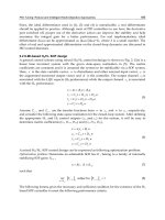
Fig. 4. Evolution of the applied torque for the Computed-Torque strategy.
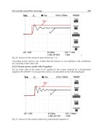
Fig. 5. Evolution of the position errors.
Fig. 6. Velocity errors.
5. Conclusions
The trajectory-tracking problem for the omnidirectional mobile robot considering its
dynamic model has been addressed and solved by means of a full state information time
varying feedback based on a methodology that exploits the passivity properties of the exact
tracking error dynamics. The asymptotic stability of the closed loop system is formally
proved. Numerical simulations are proposed to illustrate the properties of the closed-loop
system showing a better performance than the control obtained by the well known
Computed-Torque approach.
6. Acknowledgment
This work was partially supported by CONACyT México, under Grants: 61713 and 82741.
7. References
Bétourné, A. & Campion G. (1996) Dynamic Modelling and Control Design of a Class of
Omnidirectional Mobile Robots. Proceedings of the 1996 IEEE Int. Conference on
Robotics and Automation, pp. 2810-2815, Minneapolis, USA.
Campion, G.; Bastin, G. & D'Andréa-Novel, B. (1996) Structural Properties and Clasification
of Kinematics and Dynamics Models of Wheeled Mobile Robots. IEEE Transactions
on Robotics and Automation, Vol. 12, No. 1, pp. 47-61.
DynamicTrajectory-TrackingControlofan
OmnidirectionalMobileRobotBasedonaPassiveApproach 313
Fig. 4. Evolution of the applied torque for the Computed-Torque strategy.
Fig. 5. Evolution of the position errors.
Fig. 6. Velocity errors.
5. Conclusions
The trajectory-tracking problem for the omnidirectional mobile robot considering its
dynamic model has been addressed and solved by means of a full state information time
varying feedback based on a methodology that exploits the passivity properties of the exact
tracking error dynamics. The asymptotic stability of the closed loop system is formally
proved. Numerical simulations are proposed to illustrate the properties of the closed-loop
system showing a better performance than the control obtained by the well known
Computed-Torque approach.
6. Acknowledgment
This work was partially supported by CONACyT México, under Grants: 61713 and 82741.
7. References
Bétourné, A. & Campion G. (1996) Dynamic Modelling and Control Design of a Class of
Omnidirectional Mobile Robots. Proceedings of the 1996 IEEE Int. Conference on
Robotics and Automation, pp. 2810-2815, Minneapolis, USA.
Campion, G.; Bastin, G. & D'Andréa-Novel, B. (1996) Structural Properties and Clasification
of Kinematics and Dynamics Models of Wheeled Mobile Robots. IEEE Transactions
on Robotics and Automation, Vol. 12, No. 1, pp. 47-61.
AdvancesinRobotManipulators314
Canudas, C.; Siciliano, B.; Bastin, G.; Brogliato, B.; Campion, G.; D'Andrea-Novel, B. ; De
Luca, A.; Khalil, W.; Lozano, R.; Ortega, R.; Samson, C. & Tomei, P. (1996) Theory of
Robot Control. Springer-Verlag, London.
Carter, B.; Good, M.; Dorohoff, M.; Lew, J.; Williams II, R. L. & Gallina, P. (2001) Mechanical
design and modeling of an omni-directional robocup player. Proceedings RoboCup
2001 International Symposium, Seattle, WA, USA.
Chung, J. H.; Yi, B. J.; Kim, W. K. & Lee, H. (2003) The Dynamic Modeling and Analysis for
An Omnidirectional Mobile Robot with Three Caster Wheels. Proceedings of the
2003 IEEE Int. Conference on Robotics and Automation, pp. 521-527, Taipei, Taiwan.
D'Andrea-Novel, B.; Bastin, G. & Campion, G. (1992) Dynamic Feedback Linearization of
Nonholonomic Wheeled Mobile Robots. Proceedings of the IEEE International
Conference on Robotic and Automation, pp. 2527-2532, Nice, France.
Kalmár-Nagy, T.; D'Andrea, R. & Ganguly, P. (2004) Near-Optimal Dynamic Trajectory and
Control of an Omnidirectional Vehicle. Robotics and Autonomous Systems, Vol. 46,
pp. 47-64.
Liu, Y.; Wu, X.; Zhu, J. and Lew, J. (2003) Omni-directional mobile robot controller design
by trajectory linearization. Proceedings of the American Control Conference, pp. 3423-
3428, Denver, Colorado, USA.
Niño-Suárez, P. A.; Aranda-Bricaire, E. & Velasco-Villa, M. (2006) Discrete-time sliding
mode path-tracking control for a wheeled mobile robot. Proc. of the 45th IEEE
Conference on Decision and Control, pp. 3052-3057, San Diego, CA, USA.
Oriolo, G.; De Luca, A. & Venditteli, M. (2002) WMR control via dynamic feedback
linearization: Design, implementation, and experimental validation. IEEE
Transaction on Control Systems Technology, Vol. 10, No. 6, pp. 835-852.
Ortega, R.; Loria, A.; Nicklasson, P. J. & Sira-Ramírez H. (1998) Passivity-based Control of
Euler Lagrange Systems. Springer, New York, USA.
Ortega, R.; van der Schaft, A.; Mareels, I. & Maschke, B. (2001) Putting energy back in
control. IEEE Control Syst. Magazine, Vol. 21, No. 2, pp. 18-33.
Sira-Ramrez H. (2005) Are non-linear controllers really necessary in power electronics
devices?. European Power Electronics Conference EPE-2005, Dresden, Germany.
Sira-Ramrez, H. & Silva-Ortigoza, R. (2006) Design Techniques in Power Electronics Devices.
Springer-Verlag, Power Systems Series,, London. ISBN: 1-84628-458-9.
Sira-Ramírez, H. & Rodríguez-Cortés, H. (2008) Passivity Based Control of Electric Drives.
Internal Report, Centro de Investigación y de Estudios Avanzados, 2008.
Velasco-Villa M.; Alvarez-Aguirre, A. & Rivera-Zago G. (2007) Discrete-Time control of an
omnidirectional mobile robot subject to transport delay. IEEE American Control
Conference 2007, pp. 2171-2176, New York City, USA.
Velasco-Villa M.; del-Muro-Cuellar B. &Alvarez-Aguirre, A. (2007) Smith-Predictor
compensator for a delayed omnidirectional mobile robot. 15th Mediterranean
Conference on Control and Automation, T30-027, Athens, Greece.
Vázquez J. A. & Velasco-Villa M. (2008) Path-Tracking Dynamic Model Based Control of an
Omnidirectional Mobile Robot. 17th IFAC World Congress, Seoul, Korea.
Williams, R. L.; Carter, B. E.; Gallina, P. & G. Rosati. (2002) Dynamic Model With Slip for
Wheeled Omnidirectional Robots. IEEE Transactions on Robotics and Automation
,
Vol. 18, pp. 285-293.
EclecticTheoryofIntelligentRobots 315
EclecticTheoryofIntelligentRobots
E.L.Hall,S.M.AlhajAli,M.Ghaffari,X.LiaoandMingCao
X
Eclectic Theory of Intelligent Robots
E. L. Hall, S. M. Alhaj Ali*, M. Ghaffari,
X. Liao and Ming Cao
Center for Robotics Research
University of Cincinnati
Cincinnati, OH 45221-0072 USA
* The Hashemite Univ. (Jordan)
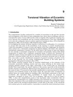
1. Introduction
The purpose of this paper is to describe a concept of eclecticism for the design, development,
simulation and implementation of a real time controller for an intelligent, vision guided
robot or robots. The use of an eclectic perceptual, creative controller that can select its own
tasks and perform autonomous operations is illustrated. This eclectic controller is a new
paradigm for robot controllers and is an attempt to simplify the application of intelligent
machines in general and robots in particular. The idea is to uses a task control center and
dynamic programming approach. However, the information required for an optimal
solution may only partially reside in a dynamic database so that some tasks are impossible
to accomplish. So a decision must be made about the feasibility of a solution to a task before
the task is attempted. Even when tasks are feasible, an iterative learning approach may be
required. The learning could go on forever. The dynamic database stores both global
environmental information and local information including the kinematic and dynamic
models of the intelligent robot. The kinematic model is very useful for position control and
simulations. However, models of the dynamics of the manipulators are needed for tracking
control of the robot’s motions. Such models are also necessary for sizing the actuators,
tuning the controller, and achieving superior performance. Simulations of various control
designs are shown. Much of the model has also been used for the actual prototype Bearcat
Cub mobile robot. This vision guided robot was designed for the Intelligent Ground Vehicle
Contest. A novel feature of the proposed approach lies in the fact that it is applicable to both
robot arm manipulators and mobile robots such as wheeled mobile robots. This generality
should encourage the development of more mobile robots with manipulator capability since
both models can be easily stored in the dynamic database. The multi task controller also
permits wide applications. The use of manipulators and mobile bases with a high-level
control are potentially useful for space exploration, manufacturing robots, defense robots,
medical robotics, and robots that aid people in daily living activities.
An important question in the application of intelligent machines is: can a major paradigm
shift can be effected from industrial robots to a more generic service robot solution? That is,
can we perform an eclectic design? (Hall, et al. 2007)
16
AdvancesinRobotManipulators316
The purpose of this paper is to examine the theory of robust learning for intelligent
machines. A main question in the application of intelligent machines is: can a major
paradigm shift can be effected?
Eclecticism as defined by Wikipedia as “ a conceptual approach that does not hold rigidly to a single
paradigm or set of assumptions, but instead draws upon multiple theories, styles, or ideas to gain
complementary insights into a subject, or applies different theories in particular cases.”
A scientific paradigm had been defined by Kuhn as “answers to the following key questions:
what is to be observed and scrutinized,
what kind of questions are supposed to be asked and probed for answers in
relation to this subject,
how are these questions are to be structured,
how should the results of scientific investigations be interpreted.
how is an experiment to be conducted, and what equipment is available to conduct
the experiment.
“Thus, within normal science, the paradigm is the set of exemplary experiments that are likely to be
copied or emulated. The prevailing paradigm often represents a more specific way of viewing reality,
or limitations on acceptable programs for future research, than the much more general scientific
method.”
In the eclectic control, some answers to the key questions are:
The performance of the intelligent machine will be observed
Actual or simulated behaviors will lead to questions of normal or useful responses
Questions should be structured to permit answers from queries of the database
Objectively by anyone in the world
Simulations are much more cost effective than actual performance tests
The proposed theory for eclectic learning is also based on the previous perceptual creative
controller for an intelligent robot that uses a multi- modal adaptive critic for performing
learning in an unsupervised situation but can also be trained for tasks in another mode and
then is permitted to operate autonomously. The robust nature is derived from the automatic
changing of task modes based on a dynamic data base and internal measurements of error at
appropriate locations in the controller.
The eclectic controller method is designed for complex real world environments. However,
analysis and simulation is needed to clarify the decision processes and reduce the danger in
real world operations.
The eclectic controller uses a perceptual creative learning architecture to integrate a Task
Control Center (TCC) and a dynamic database (DD) with adaptive critic learning algorithms
to permit these solutions. Determining the tasks to be performed and the data base to be
updated are the two key elements of the design. These new decision processes encompass
both decision and estimation theory and can be modeled by neural networks and
implemented with multi-threaded computers.
The main thrust of this paper is to present the eclectic theory of learning that can be used for
developing control architectures for intelligent machines. Emphasis will be placed on the
missing key element, the dynamic data base, since the control architectures for neural
network control of vehicles in which the kinematic and dynamic models are known but one
or more parameters must be estimated is a simple task that has been demonstrated.
The mathematical models for the kinematics and dynamics were developed and the main
emphasis was to explore the use of neural network control and demonstrate the advantages
of these learning methods. The results indicate the method of solution and its potential
application to a large number of currently unsolved problems in complex environments.
The adaptive critic neural network control is an important starting point for future learning
theories that are applicable to robust control and learning situations.
The general goal of this research is to further develop an eclectic theory of learning that is
based on human learning but applicable to machine learning and to demonstrate its
application in the design of robust intelligent systems. To obtain broadly applicable results,
a generalization of adaptive critic learning called Creative Control (CC) for intelligent robots
in complex, unstructured environments has been used. The creative control learning
architecture integrates a Task Control Center (TCC) and a Dynamic Knowledge Database
(DKD) with adaptive critic learning algorithms.
Recent learning theories such as the adaptive critic have been proposed in which a critic
provides a grade to the controller of an action module such as a robot. The creative control
process which is used is “beyond the adaptive critic.”
A mathematical model of the creative control process is presented that illustrates the use for
mobile robots.
1.1 Dynamic Programming
The intelligent robot in this paper is defined as a decision maker for a dynamic system that
may make decisions in discrete stages or over a time horizon. The outcome of each decision
may not be fully predictable but may be anticipated or estimated to some extent before the
next decision is made. Furthermore, an objective or cost function can be defined for the
decision. There may also be natural constraints. Generally, the goal is to minimize this cost
function over some decision space subject to the constraints. With this definition, the
intelligent robot can be considered as a set of problems in dynamic programming and
optimal control as defined by Bertsekas (Bertsekas, 2000).
Dynamic programming (DP) is the only approach for sequential optimization applicable to
general nonlinear and stochastic environments. However, DP needs efficient approximate
methods to overcome its dimensionality problems. It is only with the presence of artificial
neural network (ANN) and the invention of back propagation that such a powerful and
universal approximate method has become a reality.
The essence of dynamic programming is Bellman's Principle of Optimality.
(White and Sofge, 1992)
“An optimal policy has the property that whatever the initial state and initial decision are, the
remaining decisions must constitute an optimal policy with regard to the state resulting from the first
decision” (Bertsekas, 2000) (p.83).
The original Bellman equation of dynamic programming for adaptive critic algorithm may
be written as shown in Eq (1):
0
)(
)1/()))1(())(),(((max))(( UrtRJtutRUtRJ
tu
(1)
EclecticTheoryofIntelligentRobots 317
The purpose of this paper is to examine the theory of robust learning for intelligent
machines. A main question in the application of intelligent machines is: can a major
paradigm shift can be effected?
Eclecticism as defined by Wikipedia as “ a conceptual approach that does not hold rigidly to a single
paradigm or set of assumptions, but instead draws upon multiple theories, styles, or ideas to gain
complementary insights into a subject, or applies different theories in particular cases.”
A scientific paradigm had been defined by Kuhn as “answers to the following key questions:
what is to be observed and scrutinized,
what kind of questions are supposed to be asked and probed for answers in
relation to this subject,
how are these questions are to be structured,
how should the results of scientific investigations be interpreted.
how is an experiment to be conducted, and what equipment is available to conduct
the experiment.
“Thus, within normal science, the paradigm is the set of exemplary experiments that are likely to be
copied or emulated. The prevailing paradigm often represents a more specific way of viewing reality,
or limitations on acceptable programs for future research, than the much more general scientific
method.”
In the eclectic control, some answers to the key questions are:
The performance of the intelligent machine will be observed
Actual or simulated behaviors will lead to questions of normal or useful responses
Questions should be structured to permit answers from queries of the database
Objectively by anyone in the world
Simulations are much more cost effective than actual performance tests
The proposed theory for eclectic learning is also based on the previous perceptual creative
controller for an intelligent robot that uses a multi- modal adaptive critic for performing
learning in an unsupervised situation but can also be trained for tasks in another mode and
then is permitted to operate autonomously. The robust nature is derived from the automatic
changing of task modes based on a dynamic data base and internal measurements of error at
appropriate locations in the controller.
The eclectic controller method is designed for complex real world environments. However,
analysis and simulation is needed to clarify the decision processes and reduce the danger in
real world operations.
The eclectic controller uses a perceptual creative learning architecture to integrate a Task
Control Center (TCC) and a dynamic database (DD) with adaptive critic learning algorithms
to permit these solutions. Determining the tasks to be performed and the data base to be
updated are the two key elements of the design. These new decision processes encompass
both decision and estimation theory and can be modeled by neural networks and
implemented with multi-threaded computers.
The main thrust of this paper is to present the eclectic theory of learning that can be used for
developing control architectures for intelligent machines. Emphasis will be placed on the
missing key element, the dynamic data base, since the control architectures for neural
network control of vehicles in which the kinematic and dynamic models are known but one
or more parameters must be estimated is a simple task that has been demonstrated.
The mathematical models for the kinematics and dynamics were developed and the main
emphasis was to explore the use of neural network control and demonstrate the advantages
of these learning methods. The results indicate the method of solution and its potential
application to a large number of currently unsolved problems in complex environments.
The adaptive critic neural network control is an important starting point for future learning
theories that are applicable to robust control and learning situations.
The general goal of this research is to further develop an eclectic theory of learning that is
based on human learning but applicable to machine learning and to demonstrate its
application in the design of robust intelligent systems. To obtain broadly applicable results,
a generalization of adaptive critic learning called Creative Control (CC) for intelligent robots
in complex, unstructured environments has been used. The creative control learning
architecture integrates a Task Control Center (TCC) and a Dynamic Knowledge Database
(DKD) with adaptive critic learning algorithms.
Recent learning theories such as the adaptive critic have been proposed in which a critic
provides a grade to the controller of an action module such as a robot. The creative control
process which is used is “beyond the adaptive critic.”
A mathematical model of the creative control process is presented that illustrates the use for
mobile robots.
1.1 Dynamic Programming
The intelligent robot in this paper is defined as a decision maker for a dynamic system that
may make decisions in discrete stages or over a time horizon. The outcome of each decision
may not be fully predictable but may be anticipated or estimated to some extent before the
next decision is made. Furthermore, an objective or cost function can be defined for the
decision. There may also be natural constraints. Generally, the goal is to minimize this cost
function over some decision space subject to the constraints. With this definition, the
intelligent robot can be considered as a set of problems in dynamic programming and
optimal control as defined by Bertsekas (Bertsekas, 2000).
Dynamic programming (DP) is the only approach for sequential optimization applicable to
general nonlinear and stochastic environments. However, DP needs efficient approximate
methods to overcome its dimensionality problems. It is only with the presence of artificial
neural network (ANN) and the invention of back propagation that such a powerful and
universal approximate method has become a reality.
The essence of dynamic programming is Bellman's Principle of Optimality.
(White and Sofge, 1992)
“An optimal policy has the property that whatever the initial state and initial decision are, the
remaining decisions must constitute an optimal policy with regard to the state resulting from the first
decision” (Bertsekas, 2000) (p.83).
The original Bellman equation of dynamic programming for adaptive critic algorithm may
be written as shown in Eq (1):
0
)(
)1/()))1(())(),(((max))(( UrtRJtutRUtRJ
tu
(1)
AdvancesinRobotManipulators318
Where R(t) is the model of reality or state form, U( R(t),u(t)) is the utility function or local
cost, u(t) is the action vector, J(R(t)) is the criteria or cost-to-go function at time t, r and U
0
are constants that are used only in infinite-time-horizon problems and then only sometimes,
and where the angle brackets refer to expected value.
The user provides a utility function, U, and a stochastic model of the plant, R, to be
controlled. The expert system then tries to solve the Bellman equation for the chosen model
and utility function to achieve the optimum value of J by picking the action vector u(t). If an
optimum J cannot be determined, an approximate or estimate value of the J function is used
to obtain an approximate optimal solution.
Regarding the finite horizon problems, which we normally try to cope with, one can use Eq (2):
)1/()))1(())(),(((max))((
)(
rtRJtutRUtRJ
tu
(2)
Dynamic programming gives the exact solution to the problem of how to maximize a utility
function U(R(t), u(t)) over the future times, t, in a nonlinear stochastic environment.
Dynamic programming converts a difficult long-term problem in optimization over time
<U(R(t))>, the expected value of U(R(t)) over all the future times, into a much more
straightforward problem in simple, short-term function maximization – after we know the
function J. Thus, all of the approximate dynamic programming methods discussed here are
forced to use some kind of general-purpose nonlinear approximation to the J function, the
value function in the Bellman equation, or something closely related to J(Werbos, 1999).
In most forms of adaptive critic design, we approximate J by using a neural network.
Therefore, we approximate J(R) by some function
),(
ˆ
WRJ
, where W is a set of weights or
parameters,
J
ˆ
is called a critic network (Widrow, et al., 1973)
If the weights W are adapted or iteratively solved for, in real time learning or offline
iteration, we call the Critic an Adaptive Critic (Werbos, 1999).
An adaptive critic design (ACD) is any system which includes an adapted critic component;
a critic, in turn, is a neural net or other nonlinear function approximation which is trained to
converge to the function J(X).
In adaptive critic learning or designs, the critic network learns to approximate the cost-to-go
or strategic utility function J and uses the output of an action network as one of its’ inputs,
directly or indirectly. When the critic network learns, back propagation of error signals is
possible along its input feedback to the action network. To the back propagation algorithm,
this input feedback looks like another synaptic connection that needs weights adjustment.
Thus, no desired control action information or trajectory is needed as supervised learning.
2. Adaptive Critic And Creative Control
Most advanced methods in neurocontrol are based on adaptive critic learning techniques
consisting of an action network, adaptive critic network, and model or identification
network as show in Figure 1. These methods are able to control processes in such a way,
which is approximately optimal with respect to any given criteria taking into consideration
of particular nonlinear environment. For instance, when searching for an optimal trajectory
to the target position, the distance of the robot from this target position can be used as a
criteria function. The algorithm will compute the proper steering, acceleration signals for
control of vehicle, and the resulting trajectory of the vehicle will be close to optimal. During
trials (the number depends on the problem and the algorithm used) the system will improve
performance and the resulting trajectory will be close to optimal. The freedom of choice of
the criteria function makes the method applicable to a variety of problems. The ability to
derive a control strategy only from trial/error experience makes the system capable of
semantic closure. These are very strong advantages of this method.
Fig. 1. Structure of the adaptive critic controller (Jaska and Sinc, 2000)
Creative Learning Structure
It is assumed that we can use a kinematic model of a mobile robot to provide a simulated
experience to construct a value function in the critic network and to design a kinematic
based controller for the action network. A proposed diagram of creative learning algorithm
is shown in Figure 2 (Jaska and Sinc, 2000). In this proposed diagram, there are six
important components: the task control center, the dynamic knowledge database, the critic
network, the action network, the model-based action and the utility funtion. Both the critic
network and action network can be constructed by using any artificial neural networks with
sigmoidal function or radial basis function (RBF). Furthermore, the kinematic model is also
used to construct a model-based action in the framework of adaptive critic-action approach.
In this algorithm, dynamic databases are built to generalize the critic network and its
training process and provide evironmental information for decision making. It is especially
critical when the operation of mobile robots is in an unstructured environments.
Furthermore, the dynamic databases can also used to store environmental parameters such
as Global Position System (GPS) way points, map information, etc. Another component in
the diagram is the utility function for a tracking problem (error measurement). In the
EclecticTheoryofIntelligentRobots 319
Where R(t) is the model of reality or state form, U( R(t),u(t)) is the utility function or local
cost, u(t) is the action vector, J(R(t)) is the criteria or cost-to-go function at time t, r and U
0
are constants that are used only in infinite-time-horizon problems and then only sometimes,
and where the angle brackets refer to expected value.
The user provides a utility function, U, and a stochastic model of the plant, R, to be
controlled. The expert system then tries to solve the Bellman equation for the chosen model
and utility function to achieve the optimum value of J by picking the action vector u(t). If an
optimum J cannot be determined, an approximate or estimate value of the J function is used
to obtain an approximate optimal solution.
Regarding the finite horizon problems, which we normally try to cope with, one can use Eq (2):
)1/()))1(())(),(((max))((
)(
rtRJtutRUtRJ
tu
(2)
Dynamic programming gives the exact solution to the problem of how to maximize a utility
function U(R(t), u(t)) over the future times, t, in a nonlinear stochastic environment.
Dynamic programming converts a difficult long-term problem in optimization over time
<U(R(t))>, the expected value of U(R(t)) over all the future times, into a much more
straightforward problem in simple, short-term function maximization – after we know the
function J. Thus, all of the approximate dynamic programming methods discussed here are
forced to use some kind of general-purpose nonlinear approximation to the J function, the
value function in the Bellman equation, or something closely related to J(Werbos, 1999).
In most forms of adaptive critic design, we approximate J by using a neural network.
Therefore, we approximate J(R) by some function
),(
ˆ
WRJ
, where W is a set of weights or
parameters,
J
ˆ
is called a critic network (Widrow, et al., 1973)
If the weights W are adapted or iteratively solved for, in real time learning or offline
iteration, we call the Critic an Adaptive Critic (Werbos, 1999).
An adaptive critic design (ACD) is any system which includes an adapted critic component;
a critic, in turn, is a neural net or other nonlinear function approximation which is trained to
converge to the function J(X).
In adaptive critic learning or designs, the critic network learns to approximate the cost-to-go
or strategic utility function J and uses the output of an action network as one of its’ inputs,
directly or indirectly. When the critic network learns, back propagation of error signals is
possible along its input feedback to the action network. To the back propagation algorithm,
this input feedback looks like another synaptic connection that needs weights adjustment.
Thus, no desired control action information or trajectory is needed as supervised learning.
2. Adaptive Critic And Creative Control
Most advanced methods in neurocontrol are based on adaptive critic learning techniques
consisting of an action network, adaptive critic network, and model or identification
network as show in Figure 1. These methods are able to control processes in such a way,
which is approximately optimal with respect to any given criteria taking into consideration
of particular nonlinear environment. For instance, when searching for an optimal trajectory
to the target position, the distance of the robot from this target position can be used as a
criteria function. The algorithm will compute the proper steering, acceleration signals for
control of vehicle, and the resulting trajectory of the vehicle will be close to optimal. During
trials (the number depends on the problem and the algorithm used) the system will improve
performance and the resulting trajectory will be close to optimal. The freedom of choice of
the criteria function makes the method applicable to a variety of problems. The ability to
derive a control strategy only from trial/error experience makes the system capable of
semantic closure. These are very strong advantages of this method.
Fig. 1. Structure of the adaptive critic controller (Jaska and Sinc, 2000)
Creative Learning Structure
It is assumed that we can use a kinematic model of a mobile robot to provide a simulated
experience to construct a value function in the critic network and to design a kinematic
based controller for the action network. A proposed diagram of creative learning algorithm
is shown in Figure 2 (Jaska and Sinc, 2000). In this proposed diagram, there are six
important components: the task control center, the dynamic knowledge database, the critic
network, the action network, the model-based action and the utility funtion. Both the critic
network and action network can be constructed by using any artificial neural networks with
sigmoidal function or radial basis function (RBF). Furthermore, the kinematic model is also
used to construct a model-based action in the framework of adaptive critic-action approach.
In this algorithm, dynamic databases are built to generalize the critic network and its
training process and provide evironmental information for decision making. It is especially
critical when the operation of mobile robots is in an unstructured environments.
Furthermore, the dynamic databases can also used to store environmental parameters such
as Global Position System (GPS) way points, map information, etc. Another component in
the diagram is the utility function for a tracking problem (error measurement). In the
AdvancesinRobotManipulators320
diagram, X
k
, X
kd
, X
kd+1
are inputs and Y is the ouput and J(t), J(t+1) is the critic function at
the time.
Fig. 2. Proposed Creative Learning Algorithm Structure
Dynamic Knowledge Database (DKD)
The dynamic databases contain domain knowledge and can be modified to permit
adaptation to a changing environment. Dynamic knowledge databases may be called a
“neurointerface”
(Widrow and Lamego, 2002) in a dynamic filtering system based on neural
networks (NNs) and serves as a “coupler” between a task control center and a nonlinear
system or plant that is to be controlled or directed. The purpose of the coupler is to provide
the criteria functions for the adaptive critic learning system and filter the task strategies
commanded by the task control center. The proposed dynamic database contains a copy of
the model (or identification). Action and critic networks are utilized to control the plant
under nominal operation, as well as make copies of a set of parameters (or scenario)
previously adapted to deal with a plant in a known dynamic environment. The database
also stores copies of all the partial derivatives required when updating the neural networks
using backpropagation through time (Yen and Lima, 2002). The dynamic database can be
expanded to meet the requirements of complex and unstructured environments.
The data stored in the dynamic database can be uploaded to support offline or online
training of the dynamic plant and provide a model for identification of nonlinear dynamic
Dynamic
(Critic)
Knowledge
Database
…
Critic n
J(
t+1
)
Critic 2
Critic Network
Critic 1
Action
Network
Model-
based
Action
Utility
function
-
-
Z
-1
-
J(t)
Y
Xdk+1
Xk
Xk
Xdk
Xdk+1
-
Task
Control
Center
Criteria filters Adaptive critic learning system
environment with its modeling function. Another function module of the database
management is designed to analyze the data stored in the database including the sub-task
optima, pre-existing models of the network and newly added models. The task program
module is used to communicate with the task control center. The functional structure of the
proposed database management system (DBMS) is shown in Figure 3. The DBMS can be
customized from an object-relational database.
In existing models the database is considered to be static. The content of the data base may
be considered as information. However, our experience with the World Wide Web is that
the “information” is dynamic and constantly changing and often wrong.
Fig. 3. Functional structure of dynamic database
2.3 Task Control Center (TCC)
The task control center (TCC) can build task-level control systems for the creative learning
system. By "task-level", we mean the integration and coordination of perception, planning and
real-time control to achieve a given set of goals (tasks) (Lewis, et al., 1999). TCC provides a
general task control framework, and it is to be used to control a wide variety of tasks. Although
the TCC has no built-in control functions for particular tasks (such as robot path planning
algorithms), it provides control functions, such as task decomposition, monitoring, and resource
management, that are common to many applications. The particular task built-in rules or criteria
or learning J functions are managed by the dynamic database controlled with TCC to handle the
allocation of resources. The dynamic database matches the constraints on a particular control
scheme or sub-tasks or environment allocated by TCC.
The task control center acts as a decision-making system. It integrates domain knowledge or
criteria into the database of the adaptive learning system. According to Simmons (Simmons,
2002), the task control architecture for mobile robots provides a variety of control constructs that
are commonly needed in mobile robot applications, and other autonomous mobile systems. The
goal of the architecture is to enable autonomous mobile robot systems to easily specify
hierarchical task-decomposition strategies, such as how to navigate to a particular location, or
how to collect a desired sample, or how to follow a track in an unstructured environment. This
can include temporal constraints between sub-goals, leading to a variety of sequential or
concurrent behaviors. TCC schedules the execution of planned behaviors, based on those
temporal constraints acting as a decision-making control center.
T
T
a
a
s
s
k
k
C
C
o
o
n
n
t
t
r
r
o
o
l
l
C
C
e
e
n
n
t
t
e
e
r
r
…
…
D
D
y
y
n
n
a
a
m
m
i
i
c
c
D
D
a
a
t
t
a
a
b
b
a
a
s
s
e
e
A
A
n
n
a
a
l
l
y
y
s
s
i
i
s
s
M
M
o
o
d
d
e
e
l
l
i
i
n
n
T
T
a
a
s
s
k
k
P
P
r
r
o
o
g
g
r
r
a
a
m
m
A
A
d
d
a
a
p
p
t
t
i
i
v
v
e
e
C
C
r
r
i
i
t
t
i
i
c
c
M
d
d
l
l
…
…
…
…
EclecticTheoryofIntelligentRobots 321
diagram, X
k
, X
kd
, X
kd+1
are inputs and Y is the ouput and J(t), J(t+1) is the critic function at
the time.
Fig. 2. Proposed Creative Learning Algorithm Structure
Dynamic Knowledge Database (DKD)
The dynamic databases contain domain knowledge and can be modified to permit
adaptation to a changing environment. Dynamic knowledge databases may be called a
“neurointerface”
(Widrow and Lamego, 2002) in a dynamic filtering system based on neural
networks (NNs) and serves as a “coupler” between a task control center and a nonlinear
system or plant that is to be controlled or directed. The purpose of the coupler is to provide
the criteria functions for the adaptive critic learning system and filter the task strategies
commanded by the task control center. The proposed dynamic database contains a copy of
the model (or identification). Action and critic networks are utilized to control the plant
under nominal operation, as well as make copies of a set of parameters (or scenario)
previously adapted to deal with a plant in a known dynamic environment. The database
also stores copies of all the partial derivatives required when updating the neural networks
using backpropagation through time (Yen and Lima, 2002). The dynamic database can be
expanded to meet the requirements of complex and unstructured environments.
The data stored in the dynamic database can be uploaded to support offline or online
training of the dynamic plant and provide a model for identification of nonlinear dynamic
Dynamic
(Critic)
Knowledge
Database
…
Critic n
J(
t+1
)
Critic 2
Critic Network
Critic 1
Action
Network
Model-
based
Action
Utility
function
-
-
Z
-1
-
J(
t
)
Y
Xdk+1
Xk
Xk
Xdk
Xdk+1
-
Task
Control
Center
Criteria filters Adaptive critic learning system
environment with its modeling function. Another function module of the database
management is designed to analyze the data stored in the database including the sub-task
optima, pre-existing models of the network and newly added models. The task program
module is used to communicate with the task control center. The functional structure of the
proposed database management system (DBMS) is shown in Figure 3. The DBMS can be
customized from an object-relational database.
In existing models the database is considered to be static. The content of the data base may
be considered as information. However, our experience with the World Wide Web is that
the “information” is dynamic and constantly changing and often wrong.
Fig. 3. Functional structure of dynamic database
2.3 Task Control Center (TCC)
The task control center (TCC) can build task-level control systems for the creative learning
system. By "task-level", we mean the integration and coordination of perception, planning and
real-time control to achieve a given set of goals (tasks) (Lewis, et al., 1999). TCC provides a
general task control framework, and it is to be used to control a wide variety of tasks. Although
the TCC has no built-in control functions for particular tasks (such as robot path planning
algorithms), it provides control functions, such as task decomposition, monitoring, and resource
management, that are common to many applications. The particular task built-in rules or criteria
or learning J functions are managed by the dynamic database controlled with TCC to handle the
allocation of resources. The dynamic database matches the constraints on a particular control
scheme or sub-tasks or environment allocated by TCC.
The task control center acts as a decision-making system. It integrates domain knowledge or
criteria into the database of the adaptive learning system. According to Simmons (Simmons,
2002), the task control architecture for mobile robots provides a variety of control constructs that
are commonly needed in mobile robot applications, and other autonomous mobile systems. The
goal of the architecture is to enable autonomous mobile robot systems to easily specify
hierarchical task-decomposition strategies, such as how to navigate to a particular location, or
how to collect a desired sample, or how to follow a track in an unstructured environment. This
can include temporal constraints between sub-goals, leading to a variety of sequential or
concurrent behaviors. TCC schedules the execution of planned behaviors, based on those
temporal constraints acting as a decision-making control center.
T
T
a
a
s
s
k
k
C
C
o
o
n
n
t
t
r
r
o
o
l
l
C
C
e
e
n
n
t
t
e
e
r
r
…
…
D
D
y
y
n
n
a
a
m
m
i
i
c
c
D
D
a
a
t
t
a
a
b
b
a
a
s
s
e
e
A
A
n
n
a
a
l
l
y
y
s
s
i
i
s
s
M
M
o
o
d
d
e
e
l
l
i
i
n
n
T
T
a
a
s
s
k
k
P
P
r
r
o
o
g
g
r
r
a
a
m
m
A
A
d
d
a
a
p
p
t
t
i
i
v
v
e
e
C
C
r
r
i
i
t
t
i
i
c
c
M
d
d
l
l
…
…
…
…
AdvancesinRobotManipulators322
Integrating the TCC with the adaptive critic learning system and interacting with the dynamic
database, the creative learning system provides both task-level and real-time control or learning
within a single architectural framework. Through interaction with human beings to attain the
input information for the system, the TCC could decompose the task strategies to match the
dynamic database for the rules of sub-tasks by constructing a distributed system with flexible
mechanisms, which automatically provide the right data at the right time. The TCC also provides
orderly access to the resources of the dynamic database with built-in learning mechanisms
according to a queue mechanism. This is the inter-process communication capability between the
task control center and the dynamic database. The algorithm on how to link the task control
center and the dynamic database is currently done by the human designers.
Creative learning controller for intelligent robot control
Creative learning may be used to permit exploration of complex and unpredictable
environments, and even permit the discovery of unknown problems, ones that are not yet
recognized but may be critical to survival or success. By learning the domain knowledge, the
system should be able to obtain the global optima and escape local optima. The method attempts
to generalizes the highest level of human learning – imagination. As a ANN robot controller, the
block diagram of the creative controller can be presented in Figure 4.
Experience with the guidance of a mobile robot has motivated this study and has progressed
from simple line following to the more complex navigation and control in an unstructured
environment. The purpose of this system is to better understand the adaptive critic learning
theory and move forward to develop more human-intelligence-like components into the
intelligent robot controller. Moreover, it should extend to other applications. Eventually,
integrating a criteria knowledge database into the action module will develop a powerful
adaptive critic learning module.
Fig. 4. Block diagram of creative controller
Sensors
Robo
t
Y
Yd
+
+
+
Primary
Controller
Secondary
Controller
Creative
Controller
A creative controller is designed to integrate domain knowledge or criteria database and the
task control center into the adaptive critic neural network controller. It provides a needed
and well-defined structure for autonomous mobile robot application. In effect, it replaces a
human doing remote control. We have used the intelligent mobile robot as the test-bed for
the creative controller.
The task control center of the creative learning system can be considered hierarchically as
follows:
Mission for robot – e.g. mobile robot
Task for robot to follow – J : task control
Track for robot to follow
Learn non-linear system model- model discovery
Learn unknown parameters
Adaptive Critic system Implementation
Adaptive Critic system and NN
In order to develop the creative learning algorithm addressed above, we have taken a
bottom-up approach to implement adaptive critic controllers by first using neural network
for on-line or off-line learning methods.
16
Then the proposed dynamic knowledge database
and task control center are added with some to be realized in future research projects.
Tuning algorithm and stability analysis
For linear time invariant systems it is straightforward to examine stability by investigating
the poles in the s-plane. However, stability of a nonlinear dynamic systems is much more
complex, thus the stability criteria and tests are much more difficult to apply than those for
linear time invariant systems
17-19
. For general nonlinear continuous time systems, the state
space model is
)](),([ tutxfx
)](),([ tutxgy
(3)
where the nonlinear differential equation is in state variable form, x(t) is the state vector and
u(t) is the input and the second equation y(t) is the output of the system.
Creative controller and nonlinear dynamic system
For a creative controller, the task control center and the dynamic database are not time-
variable systems; therefore, the adaptive critic learning component determines the stability
of the creative controller. As it is discussed in the previous section, the adaptive critic
learning is based on critic and action network designs, which are originated from artificial
neural network (ANN), thus stability of the system is determined by the stability of the
neural networks (NN) or convergence of the critic network and action network training
procedure.
The creative controller is a nonlinear system. It is not realistic to explore all the possibilities
of the nonlinear systems and prove that the controller is in a stable state. We have used both
robot arm manipulators and mobile robot models to examine a large class of problems
known as tracking in this study. The objective of tracking is to follow a reference trajectory
as closely as possible. This may also be called optimal control since we optimize the tracking
error over time.
EclecticTheoryofIntelligentRobots 323
Integrating the TCC with the adaptive critic learning system and interacting with the dynamic
database, the creative learning system provides both task-level and real-time control or learning
within a single architectural framework. Through interaction with human beings to attain the
input information for the system, the TCC could decompose the task strategies to match the
dynamic database for the rules of sub-tasks by constructing a distributed system with flexible
mechanisms, which automatically provide the right data at the right time. The TCC also provides
orderly access to the resources of the dynamic database with built-in learning mechanisms
according to a queue mechanism. This is the inter-process communication capability between the
task control center and the dynamic database. The algorithm on how to link the task control
center and the dynamic database is currently done by the human designers.
Creative learning controller for intelligent robot control
Creative learning may be used to permit exploration of complex and unpredictable
environments, and even permit the discovery of unknown problems, ones that are not yet
recognized but may be critical to survival or success. By learning the domain knowledge, the
system should be able to obtain the global optima and escape local optima. The method attempts
to generalizes the highest level of human learning – imagination. As a ANN robot controller, the
block diagram of the creative controller can be presented in Figure 4.
Experience with the guidance of a mobile robot has motivated this study and has progressed
from simple line following to the more complex navigation and control in an unstructured
environment. The purpose of this system is to better understand the adaptive critic learning
theory and move forward to develop more human-intelligence-like components into the
intelligent robot controller. Moreover, it should extend to other applications. Eventually,
integrating a criteria knowledge database into the action module will develop a powerful
adaptive critic learning module.
Fig. 4. Block diagram of creative controller
Sensors
Robo
t
Y
Yd
+
+
+
Primary
Controller
Secondary
Controller
Creative
Controller
A creative controller is designed to integrate domain knowledge or criteria database and the
task control center into the adaptive critic neural network controller. It provides a needed
and well-defined structure for autonomous mobile robot application. In effect, it replaces a
human doing remote control. We have used the intelligent mobile robot as the test-bed for
the creative controller.
The task control center of the creative learning system can be considered hierarchically as
follows:
Mission for robot – e.g. mobile robot
Task for robot to follow – J : task control
Track for robot to follow
Learn non-linear system model- model discovery
Learn unknown parameters
Adaptive Critic system Implementation
Adaptive Critic system and NN
In order to develop the creative learning algorithm addressed above, we have taken a
bottom-up approach to implement adaptive critic controllers by first using neural network
for on-line or off-line learning methods.
16
Then the proposed dynamic knowledge database
and task control center are added with some to be realized in future research projects.
Tuning algorithm and stability analysis
For linear time invariant systems it is straightforward to examine stability by investigating
the poles in the s-plane. However, stability of a nonlinear dynamic systems is much more
complex, thus the stability criteria and tests are much more difficult to apply than those for
linear time invariant systems
17-19
. For general nonlinear continuous time systems, the state
space model is
)](),([ tutxfx
)](),([ tutxgy
(3)
where the nonlinear differential equation is in state variable form, x(t) is the state vector and
u(t) is the input and the second equation y(t) is the output of the system.
Creative controller and nonlinear dynamic system
For a creative controller, the task control center and the dynamic database are not time-
variable systems; therefore, the adaptive critic learning component determines the stability
of the creative controller. As it is discussed in the previous section, the adaptive critic
learning is based on critic and action network designs, which are originated from artificial
neural network (ANN), thus stability of the system is determined by the stability of the
neural networks (NN) or convergence of the critic network and action network training
procedure.
The creative controller is a nonlinear system. It is not realistic to explore all the possibilities
of the nonlinear systems and prove that the controller is in a stable state. We have used both
robot arm manipulators and mobile robot models to examine a large class of problems
known as tracking in this study. The objective of tracking is to follow a reference trajectory
as closely as possible. This may also be called optimal control since we optimize the tracking
error over time.
AdvancesinRobotManipulators324
Critic and Action NN Weights Tuning Algorithm
In adaptive critic learning controller, both the critic network and action network use
multilayer NN. Multilayer NN are nonlinear in the weights V and so weight tuning
algorithms that yield guaranteed stability and bounded weights in closed-loop feedback
systems have been difficult to discover until a few years ago.
3. Some Eclectic Control Scenarios
Urban Rescue Scenarios
Suppose a mobile robot is used for urban rescue as shown in Figure 5. It waits at a start
location until a call is received from a command center. Then it must go rescue a person.
Since it is in an urban environment, it must use the established roadways. Along the
roadways, it can follow pathways. However, at intersections, it must choose between
various paths to go to the next block. Therefore, it must use a different criteria at the corners
than along the track. The overall goal is to arrive at the rescue site with minimum time. To
clarify the situations consider the following steps.
1. Start location – the robot waits at this location until it receives a task command to
go to a certain location.
2. Along the path, the robot follows a road marked by lanes. It can use a minimum
mean square error between its location and the lane location during this travel.
3. At intersections, the lanes disappear but a database gives a GPS waypoint and the
location of the rescue goal.
This example requires the use of both continuous and discrete tracking, a database of known
information and multiple criteria optimization. It is possible to add a large number of real-
world issues including position estimation, perception, obstacles avoidance, communication,
etc.
Fig. 5. Simple urban rescue site
Destination
Start
A
C
B
D
Error
J1
J2
T
S
E F
G
In an unstructured environment as shown in Figure 5, we assume that information collected
about different potions of the environment could be available to the mobile robot,
improving its overall knowledge. As any robot moving autonomously in this environment
must have some mechanism for identifying the terrain and estimating the safety of the
movement between regions (blocks), it is appropriate for a coordination system to assume
that both local obstacle avoidance and a map-building module are available for the robot
which is to be controlled. The most important module in this system is the adaptive system
to learn about the environment and direct the robot action.
18
A Global Position System (GPS) may be used to measure the robot position and the distance
from the current site to the destination and provide this information to the controller to
make its decision on what to do at next move. The GPS system or other sensors could also
provides the coordinates of the obstacles for the learning module to learn the map, and then
aid in avoiding the obstacles when navigating through the intersections A, B or G, D to
destination T.
Task control center
The task control center (TCC) acts a decision-making command center. It takes
environmental perception information from sensors and other inputs to the creative
controller and derives the criteria functions. We can decompose the robot mission at the
urban rescue site shown as Figure 5 into sub-tasks as shown in Figure 6. Moving the robot
between the intersections, making decisions is based on control-center-specified criteria
functions to minimize the cost of mission. It’s appropriate to assume that J1 and J2 are the
criteria functions that the task control center will transfer to the learning system at the
beginning of the mission from the Start point to Destination (T). J1 is a function of t related
to tracking error. J2 is to minimize the distance of the robot from A to T since the cost is
directly related to the distance the robot travels.
From Start (S) to intersection A: robot follow the track SA with the J1 as objective
function
From intersection A to B or D: which one will be the next intersection, the control
center takes both J1 and J2 as objective functions.
Fig. 6. Mission decomposition diagrams
Dynamic databases
Dynamic databases would store task-oriented environment knowledge, adaptive critic
learning parameters and other related information for accomplishing the mission. In this
scenario, the robot is commanded to reach a dangerous site to conduct a rescue task. The
Urban Rescue
Follow a track
Local Navigating
Navigating to A
EclecticTheoryofIntelligentRobots 325
Critic and Action NN Weights Tuning Algorithm
In adaptive critic learning controller, both the critic network and action network use
multilayer NN. Multilayer NN are nonlinear in the weights V and so weight tuning
algorithms that yield guaranteed stability and bounded weights in closed-loop feedback
systems have been difficult to discover until a few years ago.
3. Some Eclectic Control Scenarios
Urban Rescue Scenarios
Suppose a mobile robot is used for urban rescue as shown in Figure 5. It waits at a start
location until a call is received from a command center. Then it must go rescue a person.
Since it is in an urban environment, it must use the established roadways. Along the
roadways, it can follow pathways. However, at intersections, it must choose between
various paths to go to the next block. Therefore, it must use a different criteria at the corners
than along the track. The overall goal is to arrive at the rescue site with minimum time. To
clarify the situations consider the following steps.
1. Start location – the robot waits at this location until it receives a task command to
go to a certain location.
2. Along the path, the robot follows a road marked by lanes. It can use a minimum
mean square error between its location and the lane location during this travel.
3. At intersections, the lanes disappear but a database gives a GPS waypoint and the
location of the rescue goal.
This example requires the use of both continuous and discrete tracking, a database of known
information and multiple criteria optimization. It is possible to add a large number of real-
world issues including position estimation, perception, obstacles avoidance, communication,
etc.
Fig. 5. Simple urban rescue site
Destination
Start
A
C
B
D
Error
J1
J2
T
S
E F
G
In an unstructured environment as shown in Figure 5, we assume that information collected
about different potions of the environment could be available to the mobile robot,
improving its overall knowledge. As any robot moving autonomously in this environment
must have some mechanism for identifying the terrain and estimating the safety of the
movement between regions (blocks), it is appropriate for a coordination system to assume
that both local obstacle avoidance and a map-building module are available for the robot
which is to be controlled. The most important module in this system is the adaptive system
to learn about the environment and direct the robot action.
18
A Global Position System (GPS) may be used to measure the robot position and the distance
from the current site to the destination and provide this information to the controller to
make its decision on what to do at next move. The GPS system or other sensors could also
provides the coordinates of the obstacles for the learning module to learn the map, and then
aid in avoiding the obstacles when navigating through the intersections A, B or G, D to
destination T.
Task control center
The task control center (TCC) acts a decision-making command center. It takes
environmental perception information from sensors and other inputs to the creative
controller and derives the criteria functions. We can decompose the robot mission at the
urban rescue site shown as Figure 5 into sub-tasks as shown in Figure 6. Moving the robot
between the intersections, making decisions is based on control-center-specified criteria
functions to minimize the cost of mission. It’s appropriate to assume that J1 and J2 are the
criteria functions that the task control center will transfer to the learning system at the
beginning of the mission from the Start point to Destination (T). J1 is a function of t related
to tracking error. J2 is to minimize the distance of the robot from A to T since the cost is
directly related to the distance the robot travels.
From Start (S) to intersection A: robot follow the track SA with the J1 as objective
function
From intersection A to B or D: which one will be the next intersection, the control
center takes both J1 and J2 as objective functions.
Fig. 6. Mission decomposition diagrams
Dynamic databases
Dynamic databases would store task-oriented environment knowledge, adaptive critic
learning parameters and other related information for accomplishing the mission. In this
scenario, the robot is commanded to reach a dangerous site to conduct a rescue task. The
Urban Rescue
Follow a track
Local Navigating
Navigating to A
AdvancesinRobotManipulators326
dynamic databases saved a copy of the GPS weight points S, A, B, C, D, E, F, G and T. The
map for direction and possible obstacle information is also stored in the dynamic databases.
A copy of the model parameters can be saved in the dynamic database as shown in the
simplified database Figure 7. The action model will be updated in the dynamic database if
the current training results are significantly superior to the previous model stored in the
database.
Fig. 7. Semantic dynamic database structure
Robot Learning Module
Initial plans such as road tracking and robot navigating based on known and assumed
information, can be used to incrementally revise the plan as new information is discovered
about the environment. The control center will create criteria functions according to the
revised information of the world through the user interface. These criteria functions along
with other model information of the environment will be input to the learning system. There
is a data transfer module from the control center to the learning system as well as a module
from the learning system to the dynamic database. New knowledge is used to explore and
learn, training according to the knowledge database information and then decide which to
store in the dynamic database and how to switch the criteria. The simplest style in the
adaptive critic family is heuristic dynamic programming (HDP). This is NN on-line adaptive
critic learning. There is one critic network, one action network and one model network in
the learning structure. U(t) is the utility function. R is the critic signal as J (criteria function).
The learning structure and the parameters are saved a copy in the dynamic database for the
system model searching and updating.
Other Demonstrations
The UC Robot Team is attempting to exploit its many years of autonomous ground vehicle
research experience to demonstrate its capabilities for designing and fabricating a smart
vehicle control for unmanned systems operation as shown in Figures 8, 9 and 10. The
purpose of this research is to perform a proof by demonstration through system design and
integration of a new autonomous vehicle that would integrate advanced technologies in
Creative Control with advanced autonomous robotic systems.
Database fields
Field Description
MODEL_ID Action model ID
MODEL_NAME
Action model name
UTILITY_FUN Utility function
CRITERIA_FUN
Criteria function
… …
Adaptive Critic Training Parameters
INPUT_CRITIC Input to critic network
DELT_J J(t+1)-J(t)
… …
The main thrust of our effort is the intelligent control software which provides not only
adaptation but also learning and prediction capabilities. However, since a proof by
demonstration is needed, further efforts in simulation and implementation are necessary.
This new Creative Control has been developed over the past several years and has been the
subject of many UC dissertations and papers.
Fig. 8. Bearcat Cub intelligent vehicle designed for IGVC
Fig. 9. NAC Jeep prototype at UC
Fig. 10. Hybrid Vehicle
EclecticTheoryofIntelligentRobots 327
dynamic databases saved a copy of the GPS weight points S, A, B, C, D, E, F, G and T. The
map for direction and possible obstacle information is also stored in the dynamic databases.
A copy of the model parameters can be saved in the dynamic database as shown in the
simplified database Figure 7. The action model will be updated in the dynamic database if
the current training results are significantly superior to the previous model stored in the
database.
Fig. 7. Semantic dynamic database structure
Robot Learning Module
Initial plans such as road tracking and robot navigating based on known and assumed
information, can be used to incrementally revise the plan as new information is discovered
about the environment. The control center will create criteria functions according to the
revised information of the world through the user interface. These criteria functions along
with other model information of the environment will be input to the learning system. There
is a data transfer module from the control center to the learning system as well as a module
from the learning system to the dynamic database. New knowledge is used to explore and
learn, training according to the knowledge database information and then decide which to
store in the dynamic database and how to switch the criteria. The simplest style in the
adaptive critic family is heuristic dynamic programming (HDP). This is NN on-line adaptive
critic learning. There is one critic network, one action network and one model network in
the learning structure. U(t) is the utility function. R is the critic signal as J (criteria function).
The learning structure and the parameters are saved a copy in the dynamic database for the
system model searching and updating.
Other Demonstrations
The UC Robot Team is attempting to exploit its many years of autonomous ground vehicle
research experience to demonstrate its capabilities for designing and fabricating a smart
vehicle control for unmanned systems operation as shown in Figures 8, 9 and 10. The
purpose of this research is to perform a proof by demonstration through system design and
integration of a new autonomous vehicle that would integrate advanced technologies in
Creative Control with advanced autonomous robotic systems.
Database fields
Field Description
MODEL_ID Action model ID
MODEL_NAME
Action model name
UTILITY_FUN Utility function
CRITERIA_FUN
Criteria function
… …
Adaptive Critic Training Parameters
INPUT_CRITIC Input to critic network
DELT_J J(t+1)-J(t)
… …
The main thrust of our effort is the intelligent control software which provides not only
adaptation but also learning and prediction capabilities. However, since a proof by
demonstration is needed, further efforts in simulation and implementation are necessary.
This new Creative Control has been developed over the past several years and has been the
subject of many UC dissertations and papers.
Fig. 8. Bearcat Cub intelligent vehicle designed for IGVC
Fig. 9. NAC Jeep prototype at UC
Fig. 10. Hybrid Vehicle
AdvancesinRobotManipulators328
4. CONCLUSIONS AND RECOMMENDATIONS
The eclectic control is proposed and described as a general perceptual creative adaptive
critic learning system. The task control center is a decision-making command center for the
intelligent creative learning system. The dynamic knowledge database integrates task
control center and adaptive critic learning algorithm into one system. It also provides a
knowledge domain for the task command center to perform decision-making. Furthermore,
creative learning can be used to explore complex and unpredictable environments, and even
permit the discovery of unknown problems. By learning the domain knowledge, the system
should be able to obtain the global optima and escape local optima. The challenge is now in
implementing such concepts in practical applications.
5. REFERENCES
Bertsekas, D. P., Dynamic Programming and Optimal Control, Vol. I, Second Edition,
Athena Scientific, Belmont, MA, 2000, pp. 2, 364.
Brumitt, B.L., A Mission Planning System for Multiple Mobile Robots in Unknown,
Unstructured, and Changing Environments. 1998, Carnegie Mellon University.
Campos, J., and F.L. Lewis. Adaptive Critic Neural Network for Feedforward
Compensation. in American Control Conference, 1999.
Cao, P.M, „Autonomous Runway Soil Survey System with the Fusion Of Global and Local
Navigation Mechanism‟, Ph.D. Dissertation, June 2004.
Ghaffari, M., X. Liao, E. Hall, A Model for the Natural Language Perception-based Creative
Control of Unmanned Ground Vehicles. in SPIE Conference Proceedings. 2004.
Hall, E.L. , Ghaffari, M. , Liao, X., Alhaj Ali, S.M. , Sarkar, S., Reynolds, S. and Mathur, K. ,
“Eclectic Theory of Intelligent Robots,” Proc. of Intelligent Robots and Computer
Vision, Boston, MA, SPIE 2007
Jaksa, R., and P. Sinc, Large Adaptive Critics and Mobile Robotics. July 2000.
Lewis, F.L., S. Jagannathan, and A. Yesildirek, Neural Network Control of Robot manipulators
and Nonlinear Systems. 1999, Philadelphia: Taylor and Francis.
Lewis, F.L., D.M. Dawson, and C.T. Abdallah, Robot Manipulator Control: Theory and Practice.
2nd Rev&Ex edition ed. 2003: Marcel Dekker (December 1, 2003). 430.
Liao, X., and E. Hall. Beyond Adaptive Critic - Creative Learning for Intelligent
Autonomous Mobile Robots. in Intelligent Engineering Systems Through Artificial
Neural Networks, ANNIE, in Cooperation with the IEEE Neural Network Council.
2002. St. Louis - Missouri.
Liao, X., et al. Creative Control for Intelligent Autonomous Mobile Robots. in Intelligent
Engineering Systems Through Artificial Neural Networks, ANNIE. 2003.
Pang, X. and Werbos, P.J., “Generalized Maze Navigation: SRN Critics Solve What
Feedforward or Hebbian Nets Cannot”, Systems, Man, and Cybernetics, IEEE
International Conference on, pp.1764 -1769, v.3, 1996.
Simmons, R., Task Control Architecture. TCA/www/
TCA-history.html, 2002.
Stubberud, A.R. and S.C. Stubberud, Stability, in Handbook of Industrial Automation, R.L. Shell
and E.L. Hall, Editors. 2000, MARCEL DEKKER, INC.: New York.
Syam, R. et al. Control of Nonholonomic Mobile Robot by an Adaptive Actor-Critic Method
with Simulated Experience Based Value-Functions. in Proc. of the 2002 IEEE
International Conference on Robotics and Automation. 2002.
Werbos, P.J. “Tutorial on Neurocontrol, Control Theory and Related Techniques: From
Backpropagation to Brain-Like Intelligent Systems,” the Twelfth International
Conference on Mathematical and Computer Modelling and Scientific Computing (12th
ICMCM & SC), 1999.
Systems,” the Twelfth International Conference on Mathematical and Computer Modelling and
Scientific Computing (12th ICMCM & SC), , 1999.
Werbos, P.J., “Backpropagation and Neurocontrol: a Review and Prospectus,” IJCNN Int Jt
Conf Neural Network, pp.209-216,1989.
White, D. and Sofge, D. Handbook of Intelligent Control, Van Nostrand, 1992
Widrow, B., Gupta, N. and Maitra, S. “Punish/reward: Learning with a Critic in Adaptive
Threshold Systems,” IEEE Trans. Systems, Man, Cybemetics, v.5 pp. 455-465, 1973.
Widrow, B. and Lamego, M.M. Neurointerfaces. Control Systems Technology, IEEE
Transactions on, 2002. 10(2): p. 221 -228.
Yen, G.G. and Lima, P.G., "Dynamic Database Approach for Fault Tolerant Control Using
Dual Heuristic Programming". in Proceedings of the American Control Conference.
May 2002.
This new Creative Control has been developed over the past several years and has been the
subject of many UC dissertations and papers (Cao, 2004)( Liao et al. 2003)
( Hall, et al, 2007)
EclecticTheoryofIntelligentRobots 329
4. CONCLUSIONS AND RECOMMENDATIONS
The eclectic control is proposed and described as a general perceptual creative adaptive
critic learning system. The task control center is a decision-making command center for the
intelligent creative learning system. The dynamic knowledge database integrates task
control center and adaptive critic learning algorithm into one system. It also provides a
knowledge domain for the task command center to perform decision-making. Furthermore,
creative learning can be used to explore complex and unpredictable environments, and even
permit the discovery of unknown problems. By learning the domain knowledge, the system
should be able to obtain the global optima and escape local optima. The challenge is now in
implementing such concepts in practical applications.
5. REFERENCES
Bertsekas, D. P., Dynamic Programming and Optimal Control, Vol. I, Second Edition,
Athena Scientific, Belmont, MA, 2000, pp. 2, 364.
Brumitt, B.L., A Mission Planning System for Multiple Mobile Robots in Unknown,
Unstructured, and Changing Environments. 1998, Carnegie Mellon University.
Campos, J., and F.L. Lewis. Adaptive Critic Neural Network for Feedforward
Compensation. in American Control Conference, 1999.
Cao, P.M, „Autonomous Runway Soil Survey System with the Fusion Of Global and Local
Navigation Mechanism‟, Ph.D. Dissertation, June 2004.
Ghaffari, M., X. Liao, E. Hall, A Model for the Natural Language Perception-based Creative
Control of Unmanned Ground Vehicles. in SPIE Conference Proceedings. 2004.
Hall, E.L. , Ghaffari, M. , Liao, X., Alhaj Ali, S.M. , Sarkar, S., Reynolds, S. and Mathur, K. ,
“Eclectic Theory of Intelligent Robots,” Proc. of Intelligent Robots and Computer
Vision, Boston, MA, SPIE 2007
Jaksa, R., and P. Sinc, Large Adaptive Critics and Mobile Robotics. July 2000.
Lewis, F.L., S. Jagannathan, and A. Yesildirek, Neural Network Control of Robot manipulators
and Nonlinear Systems. 1999, Philadelphia: Taylor and Francis.
Lewis, F.L., D.M. Dawson, and C.T. Abdallah, Robot Manipulator Control: Theory and Practice.
2nd Rev&Ex edition ed. 2003: Marcel Dekker (December 1, 2003). 430.
Liao, X., and E. Hall. Beyond Adaptive Critic - Creative Learning for Intelligent
Autonomous Mobile Robots. in Intelligent Engineering Systems Through Artificial
Neural Networks, ANNIE, in Cooperation with the IEEE Neural Network Council.
2002. St. Louis - Missouri.
Liao, X., et al. Creative Control for Intelligent Autonomous Mobile Robots. in Intelligent
Engineering Systems Through Artificial Neural Networks, ANNIE. 2003.
Pang, X. and Werbos, P.J., “Generalized Maze Navigation: SRN Critics Solve What
Feedforward or Hebbian Nets Cannot”, Systems, Man, and Cybernetics, IEEE
International Conference on, pp.1764 -1769, v.3, 1996.
Simmons, R., Task Control Architecture. TCA/www/
TCA-history.html, 2002.
Stubberud, A.R. and S.C. Stubberud, Stability, in Handbook of Industrial Automation, R.L. Shell
and E.L. Hall, Editors. 2000, MARCEL DEKKER, INC.: New York.
Syam, R. et al. Control of Nonholonomic Mobile Robot by an Adaptive Actor-Critic Method
with Simulated Experience Based Value-Functions. in Proc. of the 2002 IEEE
International Conference on Robotics and Automation. 2002.
Werbos, P.J. “Tutorial on Neurocontrol, Control Theory and Related Techniques: From
Backpropagation to Brain-Like Intelligent Systems,” the Twelfth International
Conference on Mathematical and Computer Modelling and Scientific Computing (12th
ICMCM & SC), 1999.
Systems,” the Twelfth International Conference on Mathematical and Computer Modelling and
Scientific Computing (12th ICMCM & SC), , 1999.
Werbos, P.J., “Backpropagation and Neurocontrol: a Review and Prospectus,” IJCNN Int Jt
Conf Neural Network, pp.209-216,1989.
White, D. and Sofge, D. Handbook of Intelligent Control, Van Nostrand, 1992
Widrow, B., Gupta, N. and Maitra, S. “Punish/reward: Learning with a Critic in Adaptive
Threshold Systems,” IEEE Trans. Systems, Man, Cybemetics, v.5 pp. 455-465, 1973.
Widrow, B. and Lamego, M.M. Neurointerfaces. Control Systems Technology, IEEE
Transactions on, 2002. 10(2): p. 221 -228.
Yen, G.G. and Lima, P.G., "Dynamic Database Approach for Fault Tolerant Control Using
Dual Heuristic Programming". in Proceedings of the American Control Conference.
May 2002.
This new Creative Control has been developed over the past several years and has been the
subject of many UC dissertations and papers (Cao, 2004)( Liao et al. 2003)
( Hall, et al, 2007)
AdvancesinRobotManipulators330
Enhancedstiffnessmodelingofserialmanipulatorswithpassivejoints 331
Enhancedstiffnessmodelingofserialmanipulatorswithpassivejoints
AnatolPashkevich,AlexandrKlimchikandDamienChablat
x
Enhanced stiffness modeling of serial
manipulators with passive joints
Anatol Pashkevich
1,2
, Alexandr Klimchik
1,2
and Damien Chablat
2
1
Ecole des Mines de Nantes
2
Institut de Recherches en Communications et Cybernetique de Nantes
France
Abstract
The chapter focuses on the enhanced stiffness modeling and analysis of serial kinematic
chains with passive joints, which are widely used in parallel robotic systems. In contrast to
previous works, the stiffness is evaluated for the loaded working mode corresponding to the
static equilibrium of the elastic forces and the external wrench acting upon the manipulator
end point. It is assumed that the manipulator elasticity is described by a multidimensional
lumped-parameter model, which consists of a chain of rigid bodies connected by 6-dof
virtual springs. Each of these springs characterize flexibility of the corresponding link or
actuating joint and takes into account both their translational/rotational compliance and the
coupling between them. The proposed technique allows finding the full-scale “load-
deflection” relation for any given workspace point and to linearise it taking into account
variation of the manipulator Jacobian due to the external load. These enable evaluating
critical forces that may provoke non-linear behavior of the manipulator, such as sudden
failure due to elastic instability (buckling). The advantages of the developed technique are
illustrated by several examples that deal with kinematic chains employed in typical parallel
manipulators.
Keywords
Stiffness model, external loading, kinetostatic analysis, passive joints, buckling, divergence
of equilibrium, static stability
1. Introduction
Due to the increasing industrial needs, novel approaches in mechanical design of robotic
manipulators are targeted at essential reduction of moving masses and achieving high
dynamic performances with relatively low energy consumption. This motivates using
advanced kinematical architectures and light-weight materials, as well as minimization of
the cross-sections of all manipulator elements (Siciliano & Khatib, 2008). The primary
constraint for such minimization is the mechanical stiffness of the manipulator, which must
be evaluated taking into account external disturbances (loading) imposed by a relevant
17
AdvancesinRobotManipulators332
manufacturing process. However, in robotic literature, the manipulator stiffness is usually
evaluated by a linear model, which defines the static response to the external force/torque,
assuming that the compliant deflections are small and the external loading is insignificant
(Zhang et al., 2009; Majou et al., 2007). At the same time, in many practical applications
(such as milling, for instance), the loading is essential and conventional stiffness modeling
techniques must be used with great caution (Los et al., 2008). Moreover, for the
manipulators with light-weight links, there is a potential danger of buckling phenomena
that is known from general theory of elastic stability (Timoshenko & Goodier, 1970). Hence,
the existing stiffness modeling techniques for high-performance robotic manipulators must
be revised and enhanced, in order to add ability of detecting non-linear effects and avoid
structural failures caused by the loading.
The existing approaches for the manipulator stiffness modeling may be roughly divided into
three main groups: the Finite Element Analysis (FEA) (Piras et al., 2005; Hu et al., 2007;
Nagai
& Liu 2007), the matrix structural analysis (SMA) (Deblaise et al. 2006, Martin, 1966,
Li et al., 2002), and the virtual joint method (VJM) that is often called the lumped modeling
(Gosselin, 1990; Pashkevich et. al. 2008; Quennouelle & Gosselin 2008 a). The most accurate
of them is the Finite Element Analysis, which allows modeling links and joints with its true
dimension and shape. However it is usually applied at the final design stage because of the
high computational expenses required for the repeated remeshing of the complicated 3D
structure over the whole workspace. The SMA also incorporates the main ideas of the FEA,
but operates with rather large elements – 3D flexible beams that are presented in the
manipulator structure. This leads obviously to the reduction of the computational expenses,
but does not provide clear physical relations required for the parametric stiffness analysis.
And finally, the VJM method is based on the expansion of the traditional rigid model by
adding the virtual joints (localized springs), which describe the elastic deformations of the
links, joints and actuators (Salisbury, 1980; Gosselin, 1990). The VJM technique is widely
used at the pre-design stage and will be extended in this paper for the case of the preloaded
manipulators.
It should be noted, that there are a number of variations and simplifications of the VJM,
which differ in modeling assumptions and numerical procedures. Recent modification of
this method allows to extend it to the over-constrained manipulator and to apply it at any
workspace point, including the singular ones (Pashkevich et. al. 2009 a, b). Besides, to take
into account real shape of the manipulator components, the stiffness parameters may be
evaluated using the FEA modeling. The latter provided the FEA-accuracy throughout the
whole workspace without exhaustive remeshing required for the classical FEA.
At present, there is very limited number of publication that directly addressed the problem
of the stiffness modeling for loaded manipulators. The most essential results were obtained
in (Alici, & Shirinzadeh; 2005; Quennouelle & Gosselin, 2008 b; Kovecses & Angeles, 2007)
where the stiffness matrix was computed taking into account the change in the manipulator
configuration due to the preloading. However, the problem of finding the corresponding
loaded equilibrium was omitted, so the Jacobian and Hessian were computed in a
traditional way, i.e. for the neighborhood of the unloaded equilibrium. The latter yielded
essential computational simplification but also imposed crucial limitations, not allowing
detecting the buckling and other non-liner effects.
This chapter focuses on the stiffness modeling of serial kinematic chains with passive joints,
which are widely used in parallel robotic systems. It presents an enhanced solution of the
considered problem, taking into account influence of the external force/torque on the
manipulator configuration as well as change in the Jacobian due to the external loading. It
implements the virtual joint technique that describes the compliance of the manipulator
elements by a set of localized six-dimensional springs separated by rigid links and perfect
joints. In contrast to previous works, the developed technique allows to obtain the full-scale
“load-deflection” relation for any given workspace point and to compute the desired matrix
for any manipulator configuration (including singular ones), implicitly taking into account
the kinematic redundancy imposed by the passive joints. Besides, it enables designer to
evaluate critical forces that may provoke non-linear manipulator behaviour, such as sudden
failure due to elastic instability (buckling) which has not been previously studied in robotic
literature. Another contribution is a numerical algorithm for computing the loaded
equilibrium and its analytical criteria for its stability analysis.
The remainder of the chapter is organized as follows. Section 2 defines the research problem
and basic assumptions. In Section 3, it is proposed a numerical algorithm for computing of
the loaded static equilibrium and its stability analysis. Section 4 focuses on the stiffness
matrix evaluation taking into account external loading and presence of passive joints.
Section 5 contains a set of illustrative examples that demonstrate possible nonlinear
behavior of loaded serial kinematic chains. And finally, Section 6 summarizes the main
results and contributions.
2. Problem of Stiffness modelling
2.1 Manipulator Architecture
Let us consider a general serial kinematic chain, which consists of a fixed “Base”, a number
of flexible actuated joints “Ac”, a serial chain of flexible “Links”, a number of passive joints
“Ps” and a moving “Platform” at the end of the chain (Fig. 1). It is assumed that all links are
separated by the joints (actuated or passive, rotational or translational) and the joint type
order is arbitrary. Besides, it is admitted that some links may be separated by actuated and
passive joints simultaneously. Such architecture can be found in most of parallel
manipulators (Fig. 2) where several similar kinematic chains are connected to the same base
and platform in a different way (with rotation of 90° or 120°, for instance), in order to
eliminate the redundancy caused by the passive joints. It is obvious that such kinematic
chains are statically under-constrained and their stiffness analysis can not be performed by
direct application of the standard methods.
Typical examples of the examined kinematic chains can be found in 3-PUU translational
parallel kinematic machine (Li & Xu, 2008), in Delta parallel robot (Clavel, 1988) or in
parallel manipulators of the Orthoglide family (Chablat & Wenger, 2003) and other
manipulators (Merlet, 2006). It worth mentioning that here a specific spatial arrangement of
under-constrained chains yields the over-constrained mechanism that posses a high structural
rigidity with respect to the external force. In particular, for Orthoglide, each kinematic chain
prevents the platform from rotating about two orthogonal axes and any combination of two
kinematic chains suppresses all possible rotations of the platform. Hence, the whole set of
three kinematic chains produces non-singular stiffness matrix while for each separate chain
the stiffness matrix is singular. This motivates development of dedicated stiffness analysis
techniques that are presented below.
Enhancedstiffnessmodelingofserialmanipulatorswithpassivejoints 333
manufacturing process. However, in robotic literature, the manipulator stiffness is usually
evaluated by a linear model, which defines the static response to the external force/torque,
assuming that the compliant deflections are small and the external loading is insignificant
(Zhang et al., 2009; Majou et al., 2007). At the same time, in many practical applications
(such as milling, for instance), the loading is essential and conventional stiffness modeling
techniques must be used with great caution (Los et al., 2008). Moreover, for the
manipulators with light-weight links, there is a potential danger of buckling phenomena
that is known from general theory of elastic stability (Timoshenko & Goodier, 1970). Hence,
the existing stiffness modeling techniques for high-performance robotic manipulators must
be revised and enhanced, in order to add ability of detecting non-linear effects and avoid
structural failures caused by the loading.
The existing approaches for the manipulator stiffness modeling may be roughly divided into
three main groups: the Finite Element Analysis (FEA) (Piras et al., 2005; Hu et al., 2007;
Nagai
& Liu 2007), the matrix structural analysis (SMA) (Deblaise et al. 2006, Martin, 1966,
Li et al., 2002), and the virtual joint method (VJM) that is often called the lumped modeling
(Gosselin, 1990; Pashkevich et. al. 2008; Quennouelle & Gosselin 2008 a). The most accurate
of them is the Finite Element Analysis, which allows modeling links and joints with its true
dimension and shape. However it is usually applied at the final design stage because of the
high computational expenses required for the repeated remeshing of the complicated 3D
structure over the whole workspace. The SMA also incorporates the main ideas of the FEA,
but operates with rather large elements – 3D flexible beams that are presented in the
manipulator structure. This leads obviously to the reduction of the computational expenses,
but does not provide clear physical relations required for the parametric stiffness analysis.
And finally, the VJM method is based on the expansion of the traditional rigid model by
adding the virtual joints (localized springs), which describe the elastic deformations of the
links, joints and actuators (Salisbury, 1980; Gosselin, 1990). The VJM technique is widely
used at the pre-design stage and will be extended in this paper for the case of the preloaded
manipulators.
It should be noted, that there are a number of variations and simplifications of the VJM,
which differ in modeling assumptions and numerical procedures. Recent modification of
this method allows to extend it to the over-constrained manipulator and to apply it at any
workspace point, including the singular ones (Pashkevich et. al. 2009 a, b). Besides, to take
into account real shape of the manipulator components, the stiffness parameters may be
evaluated using the FEA modeling. The latter provided the FEA-accuracy throughout the
whole workspace without exhaustive remeshing required for the classical FEA.
At present, there is very limited number of publication that directly addressed the problem
of the stiffness modeling for loaded manipulators. The most essential results were obtained
in (Alici, & Shirinzadeh; 2005; Quennouelle & Gosselin, 2008 b; Kovecses & Angeles, 2007)
where the stiffness matrix was computed taking into account the change in the manipulator
configuration due to the preloading. However, the problem of finding the corresponding
loaded equilibrium was omitted, so the Jacobian and Hessian were computed in a
traditional way, i.e. for the neighborhood of the unloaded equilibrium. The latter yielded
essential computational simplification but also imposed crucial limitations, not allowing
detecting the buckling and other non-liner effects.
This chapter focuses on the stiffness modeling of serial kinematic chains with passive joints,
which are widely used in parallel robotic systems. It presents an enhanced solution of the
considered problem, taking into account influence of the external force/torque on the
manipulator configuration as well as change in the Jacobian due to the external loading. It
implements the virtual joint technique that describes the compliance of the manipulator
elements by a set of localized six-dimensional springs separated by rigid links and perfect
joints. In contrast to previous works, the developed technique allows to obtain the full-scale
“load-deflection” relation for any given workspace point and to compute the desired matrix
for any manipulator configuration (including singular ones), implicitly taking into account
the kinematic redundancy imposed by the passive joints. Besides, it enables designer to
evaluate critical forces that may provoke non-linear manipulator behaviour, such as sudden
failure due to elastic instability (buckling) which has not been previously studied in robotic
literature. Another contribution is a numerical algorithm for computing the loaded
equilibrium and its analytical criteria for its stability analysis.
The remainder of the chapter is organized as follows. Section 2 defines the research problem
and basic assumptions. In Section 3, it is proposed a numerical algorithm for computing of
the loaded static equilibrium and its stability analysis. Section 4 focuses on the stiffness
matrix evaluation taking into account external loading and presence of passive joints.
Section 5 contains a set of illustrative examples that demonstrate possible nonlinear
behavior of loaded serial kinematic chains. And finally, Section 6 summarizes the main
results and contributions.
2. Problem of Stiffness modelling
2.1 Manipulator Architecture
Let us consider a general serial kinematic chain, which consists of a fixed “Base”, a number
of flexible actuated joints “Ac”, a serial chain of flexible “Links”, a number of passive joints
“Ps” and a moving “Platform” at the end of the chain (Fig. 1). It is assumed that all links are
separated by the joints (actuated or passive, rotational or translational) and the joint type
order is arbitrary. Besides, it is admitted that some links may be separated by actuated and
passive joints simultaneously. Such architecture can be found in most of parallel
manipulators (Fig. 2) where several similar kinematic chains are connected to the same base
and platform in a different way (with rotation of 90° or 120°, for instance), in order to
eliminate the redundancy caused by the passive joints. It is obvious that such kinematic
chains are statically under-constrained and their stiffness analysis can not be performed by
direct application of the standard methods.
Typical examples of the examined kinematic chains can be found in 3-PUU translational
parallel kinematic machine (Li & Xu, 2008), in Delta parallel robot (Clavel, 1988) or in
parallel manipulators of the Orthoglide family (Chablat & Wenger, 2003) and other
manipulators (Merlet, 2006). It worth mentioning that here a specific spatial arrangement of
under-constrained chains yields the over-constrained mechanism that posses a high structural
rigidity with respect to the external force. In particular, for Orthoglide, each kinematic chain
prevents the platform from rotating about two orthogonal axes and any combination of two
kinematic chains suppresses all possible rotations of the platform. Hence, the whole set of
three kinematic chains produces non-singular stiffness matrix while for each separate chain
the stiffness matrix is singular. This motivates development of dedicated stiffness analysis
techniques that are presented below.
AdvancesinRobotManipulators334
Fig. 1. General serial kinematic chain and its VJM model (Ac – actuated joint, Ps – passive
joint).
Fig. 2. Architecture of typical parallel manipulators and their kinematics chains
2.2 Basic Assumptions
To evaluate the stiffness of the considered serial manipulator, let us apply a modification of
the virtual joint method (VJM), which is based on the lump modeling approach (Gosselin,
1990). According to this approach, the original rigid model should be extended by adding
virtual joints (localized springs), which describe elastic deformations of the links. Besides,
virtual springs are included in the actuating joints, to take into account the stiffness of the
control loop. Under such assumptions, the kinematic chain can be described by the
following serial structure:
(a) a rigid link between the manipulator base and the first actuating joint described by the
constant homogenous transformation matrix
Base
T ;
(b) the 6-d.o.f. actuating joints defining three translational and three rotational actuator
coordinates, which are described by the homogenous matrix function
3
i
D
a
T θ where
, , , , ,
i ai ai ai ai ai ai
a x y z x y z
θ are the virtual spring coordinates;
(c) the 6-d.o.f. passive joints defining three translational and three rotational passive joins
coordinates, which are described by the homogenous matrix function
3
i
D
p
T q where
, , , , ,
i i i i i i i
p
x y z x y z
q q q q q q
q are the passive joint coordinates;
(d) the rigid links, which are described by the constant homogenous transformation matrix
i
L
ink
T ;
(e) a 6-d.o.f. virtual joint defining three translational and three rotational link-springs, which
are described by the homogenous matrix function
3
i
D
Link
T θ , where
, , , , ,
i i i i i i i
L
ink x y z x y z
θ ,
, ,
i i i
x
y z
and
, ,
i i i
x
y z
correspond to the elementary
translations and rotations respectively;
(f) a rigid link from the last link to the end-effector, described by the homogenous matrix
transformation
Tool
T
.
In the frame of these notations, the final expression defining the end-effector location subject
to variations of all joint coordinates of a single kinematic chain may be written as the
product of the following homogenous matrices
2 1 2
3 3 3 3
i i i i i
B
ase D a D p Link D Link D p Tool
i
T T T θ T q T T θ T q T
(1)
where the components
3
, ( ), ,
i
B
ase D Link Tool
T T T T may be factorized with respect to the terms
including the joint variables, in order to simplify computing of the derivatives (Jacobian and
Hessian) .
This expression includes both traditional geometric variables (passive and active joint
coordinates) and stiffness variables (virtual joint coordinates). Explicit position and
orientation of the end-effector can by extracted from the matrix
T
in a standard way
(Angeles, 2007) , so finally the kinematic model can be rewritten as the vector function
( , )t g
q θ (2)
where the vector
( , )
T
t p φ includes the position ( , , )
T
x
y zp and orientation
( , , )
T
x y z
φ of the end-platform, the vector
1 2
( , , , )
T
n
q q qq contains all passive joint
coordinates, the vector
1 2
( , , , )
T
m
θ collects all virtual joint coordinates, n is the
number of passive joins,
m
is the number of virtual joints.
2.3 Problem statement
In general, the stiffness model describes the resistance of an elastic body or a mechanism to
deformations caused by an external force or torque. It can be defined by the relation
( )fF Δt , where ( )f is the function that associates a deformation Δt with an external
force F that causes it. It worth mentioning that the function ( )f can de determined even
for the singular configurations (or redundant kinematics) while the inverse statement is not
generally true. For relatively small deformations, this function is defined through the
‘‘stiffness matrix”
K , which defines the linear relation
0 0
( , )
F K q θ Δt (3)
between the six-dimensional translational/rotational displacements
(Δ , Δ , Δ , Δ , Δ , Δ )
T
x y z
x y z Δt , and the static forces/torques
, , , , ,
x
y z x y z
F F F M M MF
causing this transition. Here, the vector
0 01 02 0
( , , , )
T
n
q q qq includes all passive joint
coordinates, the vector
0 01 02 0
( , , , )
T
m
θ collects all virtual joint coordinates, n is the
Enhancedstiffnessmodelingofserialmanipulatorswithpassivejoints 335
Fig. 1. General serial kinematic chain and its VJM model (Ac – actuated joint, Ps – passive
joint).
Fig. 2. Architecture of typical parallel manipulators and their kinematics chains
2.2 Basic Assumptions
To evaluate the stiffness of the considered serial manipulator, let us apply a modification of
the virtual joint method (VJM), which is based on the lump modeling approach (Gosselin,
1990). According to this approach, the original rigid model should be extended by adding
virtual joints (localized springs), which describe elastic deformations of the links. Besides,
virtual springs are included in the actuating joints, to take into account the stiffness of the
control loop. Under such assumptions, the kinematic chain can be described by the
following serial structure:
(a) a rigid link between the manipulator base and the first actuating joint described by the
constant homogenous transformation matrix
Base
T ;
(b) the 6-d.o.f. actuating joints defining three translational and three rotational actuator
coordinates, which are described by the homogenous matrix function
3
i
D
a
T θ where
, , , , ,
i ai ai ai ai ai ai
a x y z x y z
θ are the virtual spring coordinates;
(c) the 6-d.o.f. passive joints defining three translational and three rotational passive joins
coordinates, which are described by the homogenous matrix function
3
i
D
p
T q where
, , , , ,
i i i i i i i
p
x y z x y z
q q q q q q
q are the passive joint coordinates;
(d) the rigid links, which are described by the constant homogenous transformation matrix
i
L
ink
T ;
(e) a 6-d.o.f. virtual joint defining three translational and three rotational link-springs, which
are described by the homogenous matrix function
3
i
D
Link
T θ , where
, , , , ,
i i i i i i i
L
ink x y z x y z
θ ,
, ,
i i i
x
y z
and
, ,
i i i
x
y z
correspond to the elementary
translations and rotations respectively;
(f) a rigid link from the last link to the end-effector, described by the homogenous matrix
transformation
Tool
T
.
In the frame of these notations, the final expression defining the end-effector location subject
to variations of all joint coordinates of a single kinematic chain may be written as the
product of the following homogenous matrices
2 1 2
3 3 3 3
i i i i i
B
ase D a D p Link D Link D p Tool
i
T T T θ T q T T θ T q T
(1)
where the components
3
, ( ), ,
i
B
ase D Link Tool
T T T T may be factorized with respect to the terms
including the joint variables, in order to simplify computing of the derivatives (Jacobian and
Hessian) .
This expression includes both traditional geometric variables (passive and active joint
coordinates) and stiffness variables (virtual joint coordinates). Explicit position and
orientation of the end-effector can by extracted from the matrix
T
in a standard way
(Angeles, 2007) , so finally the kinematic model can be rewritten as the vector function
( , )t g q θ (2)
where the vector
( , )
T
t p φ includes the position ( , , )
T
x
y zp and orientation
( , , )
T
x y z
φ of the end-platform, the vector
1 2
( , , , )
T
n
q q qq contains all passive joint
coordinates, the vector
1 2
( , , , )
T
m
θ collects all virtual joint coordinates, n is the
number of passive joins,
m
is the number of virtual joints.
2.3 Problem statement
In general, the stiffness model describes the resistance of an elastic body or a mechanism to
deformations caused by an external force or torque. It can be defined by the relation
( )fF Δt , where ( )f is the function that associates a deformation Δt with an external
force F that causes it. It worth mentioning that the function ( )f can de determined even
for the singular configurations (or redundant kinematics) while the inverse statement is not
generally true. For relatively small deformations, this function is defined through the
‘‘stiffness matrix”
K , which defines the linear relation
0 0
( , ) F K q θ Δt (3)
between the six-dimensional translational/rotational displacements
(Δ , Δ , Δ , Δ , Δ , Δ )
T
x y z
x y z Δt , and the static forces/torques
, , , , ,
x
y z x y z
F F F M M MF
causing this transition. Here, the vector
0 01 02 0
( , , , )
T
n
q q qq includes all passive joint
coordinates, the vector
0 01 02 0
( , , , )
T
m
θ collects all virtual joint coordinates, n is the