Design and implementation an iot application platform for salangane house management system
Bạn đang xem bản rút gọn của tài liệu. Xem và tải ngay bản đầy đủ của tài liệu tại đây (9.25 MB, 99 trang )
MINISTRY OF EDUCATION AND TRAINING
HO CHI MINH CITY UNIVERSITY OF TECHNOLOGY AND EDUCATION
GRADUATION PROJECT
COMPUTER ENGINEERING TECHNOLOGY
DESIGN AND IMPLEMENTATION AN IOT
APPLICATION PLATFORM FOR SALANGANE
HOUSE MANAGEMENT SYSTEM
LECTURER: TRUONG QUANG PHUC, M.Eng
STUDENT: PHAN TAN DUNG
NGUYEN VAN DAO
SKL010592
Ho Chi Minh City, December 2022
HO CHI MINH CITY UNIVERSITY OF TECHNOLOGY AND
EDUCATION
FACULTY FOR HIGH QUALITY TRAINING
GRADUATION PROJECT
DESIGN AND IMPLEMENTATION AN IOT
APPLICATION PLATFORM FOR SALANGANE
HOUSE MANAGEMENT SYSTEM
PHAN TẤN DŨNG
Student ID: 18119011
NGUYỄN VĂN ĐẠO
Student ID: 18119013
Major: COMPUTER ENGINEERING TECHNOLOGY
Advisor: TRƯƠNG QUANG PHÚC, M.Eng
Ho Chi Minh City, December 2022
THE SOCIALIST REPUBLIC OF VIETNAM
Independence – Freedom– Happiness
-------Ho Chi Minh City, December 17, 2022
GRADUATION PROJECT ASSIGNMENT
Student name: Phan Tấn Dũng
Student ID: 18119011
Student name: Nguyễn Văn Đạo
Student ID: 18119013
Major: Computer Engineering Technology
Class: 18119CLA
Advisor: Trương Quang Phúc, MEng
Phone number: _________________
Date of assignment: _____________________
Date of submission: _____________
1. Project title: Design and Implementation an IoT Application Platform for Salangane House Management
System
2. Initial materials provided by the advisor: ___________________________________
3. Content of the project: _________________________________________________
4. Final product: ________________________________________________________
CHAIR OF THE PROGRAM
ADVISOR
(Sign with full name)
(Sign with full name)
Trương Quang Phúc
THE SOCIALIST REPUBLIC OF VIETNAM
Independence – Freedom– Happiness
-------Ho Chi Minh City, December 17, 2022
ADVISOR’S EVALUATION SHEET
Student name: Phan Tấn Dũng
Student ID: 18119011
Student name: Nguyễn Văn Đạo
Student ID: 18119013
Major: Computer Engineering Technology
Project title: Design and Implementation an IoT Application Platform for Salangane House
Management System
Advisor: Trương Quang Phúc, M.Eng
EVALUATION
1. Content of the project:
.................................................................................................................................................
.................................................................................................................................................
2. Strengths:
.................................................................................................................................................
.................................................................................................................................................
3. Weaknesses:
.................................................................................................................................................
.................................................................................................................................................
4. Approval for oral defense? (Approved or denied)
Approved
5. Overall evaluation: (Excellent, Good, Fair, Poor)
Good
6. Mark: 9.0 (in words: .........................................................................................)
Ho Chi Minh City, Dec 17, 2022
ADVISOR
(Sign with full name)
Trương Quang Phúc
HO CHI MINH CITY OF UNIVERSITY OF
TECHNOLOGY AND EDUCATION
FACULTY OF HIGH QUALITY TRAINING
SOCIALIST REPUBLIC OF VIETNAM
Independence – Freedom – Happiness
Ho Chi Minh City, January 10, 2023
MODIFYING EXPLANATION OF THE GRADUATION PROJECT
MAJOR: COMPUTER TECHNOLOGY ENGINEERING
1. Project title: Design and Implementation an IoT Application Platform for
Salangane House Management System.
2. Student name: Nguyễn Văn Đạo
ID: 18119013
Student name: Phan Tấn Dũng
ID: 18119011
3. Advisor: Trương Quang Phúc, M. Eng
4. Defending Council: Council 2, Room: A3-404, 3rd January 2023.
5. Modifying explanation of the graduation project:
No
Council comments
Editing results
Note
“System requirement” is in chapter 3.
Added
“Customer
needs”
and
“Specifications” in chapter 3.
1
Provide requirements,
specifications in details.
2
Parameter values that are selected for
Authors should show the parameter
design are modified and added in
values which are selected for
“HARDWARE”
(chapter
2)
and
design. What are requirements of
“SPECIFICATIONS” (chapter 3), and
system?
“System requirement” is in chapter 3.
3
Authors should consider interaction
of parameters each other. The
variation in the temperature can
affect humidity for example.
Head of Department
(Sign with full name)
The temperature and humidity parameters
are considered for auto mode that is shown
in “Central processing unit block” in
chapter 3.
Advisor
(Sign with full name)
Students
(Sign with full name)
Trương Quang Phúc
Số hiệu: BM16/QT-PKHCN-QHQT-NCKH/02 Lần soát xét: 02
Ngày hiệu lực: 01/4/2020
Trang: 1/1
THE SOCIALIST REPUBLIC OF VIETNAM
Independence – Freedom– Happiness
-------Ho Chi Minh City, December 17, 2022
PRE-DEFENSE EVALUATION SHEET
Student name: Phan Tấn Dũng
Student ID: 18119011
Student name: Nguyễn Văn Đạo
Student ID: 18119013
Major: Computer Engineering Technology
Project title: Design and Implementation an IoT Application Platform for Salangane House
Management System
Name of Reviewer: .................................................................................................................
EVALUATION
1. Content and workload of the project
.................................................................................................................................................
.................................................................................................................................................
.................................................................................................................................................
.................................................................................................................................................
2. Strengths:
.................................................................................................................................................
.................................................................................................................................................
.................................................................................................................................................
3. Weaknesses:
.................................................................................................................................................
.................................................................................................................................................
.................................................................................................................................................
4. Approval for oral defense? (Approved or denied)
.................................................................................................................................................
5. Overall evaluation: (Excellent, Good, Fair, Poor)
.................................................................................................................................................
6. Mark:……………….(in words: ........................................................................................)
Ho Chi Minh City, month day, year
REVIEWER
(Sign with full name)
THE SOCIALIST REPUBLIC OF VIETNAM
Independence – Freedom– Happiness
--------
EVALUATION SHEET OF
DEFENSE COMMITTEE MEMBER
Student name: Phan Tấn Dũng
Student ID: 18119011
Student name: Nguyễn Văn Đạo
Student ID: 18119013
Major: Computer Engineering Technology
Project title: Design and Implementation an IoT Application Platform for Salangane House
Management System
Name of Defense Committee Member:
...................................................................................................................................................
EVALUATION
1. Content and workload of the project
.................................................................................................................................................
.................................................................................................................................................
.................................................................................................................................................
.................................................................................................................................................
2. Strengths:
.................................................................................................................................................
.................................................................................................................................................
.................................................................................................................................................
3. Weaknesses:
.................................................................................................................................................
.................................................................................................................................................
.................................................................................................................................................
4. Overall evaluation: (Excellent, Good, Fair, Poor)
.................................................................................................................................................
5. Mark:……………….(in words: ........................................................................................)
Ho Chi Minh City, …, …, …
COMMITTEE MEMBER
(Sign with full name)
SUPERVISOR APPROVAL
……………………………………………………………………………………
…………………………………………………………………………………………
…………………………………………………………………………………………
…………………………………………………………………………………………
…………………………………………………………………………………………
…………………………………………………………………………………………
…………………………………………………………………………………………
…………………………………………………………………………………………
…………………………………………………………………………………………
…………………………………………………………………………………………
…………………………………………………………………………………………
……………………………………………………………….…………………………
…………………………………………………………………………………………
…………………………………………………………………………………………
…………………………………………………………………………………………
…………………………………………………………………………………………
…………………………………………………………………………………………
…………………………………………………………………………………………
…………………………………………………………………………………………
…………………………………………………………………………………………
…………………………………………………………………………………………
…………………………………………………………………………………………
…………………………………….……………………………………………………
…………………………………………………………………………………………
…………………………………………………………………………………………
…………………………………………………………………………………………
…………………………………………………………………………………………
…………………………………………………………………………………………
…………………………………………………………………………………………
…………………………………………………………………………………………
…………………………………………………………………………………………
…………………………………………………………………………………………
…………………………………………………………………………………………
………….………………………………………………………………………………
…………………………………………………………………………………………
…………………………………………………………………………………………
…………………………………………………………………………………………
…………………………………………………………………………………………
…………………………………………………………………………………………
…………………………………………………………………………………………
…………………………………………………………………………………………
…………………………………………………………………………………………
…………………………………………………………………………………………
i
ACKNOWLEDGMENTS
We would like to thank all of the teachers in Faculty for High Quality Training
who instructed the valuable knowledge in our major for my team. We appreciate this
knowledge to complete our graduation thesis.
We would like to express our very great appreciation to TRUONG QUANG
PHUC, M.Eng for his valuable advice during the planning, designing, and finishing of
this project. His guidance helped my team to be able to enhance the idea and develop
this project.
We would also like to extend our thanks to all of the great classmates in class
18119CLA who gave many essential comments to contribute to this project.
Finally, although we complete and achieve some goals in this project, there are
also some inevitable defects in this project. We hope teachers and classmates
sympathize with the problems. We wish to receive advices from teachers and
classmates.
Thank you very much!
ii
ABSTRACT
In this project, we built an IoT Platform using Wi-Fi communication protocol to
support users to be able to observe some environmental parameters such as
temperature value, humidity value, light value and operation states of some devices
such as a speaker, fans, a light bulb, a humidifier in the salangane house. This system
will collect environmental data by reading data from sensors. The environment data
will be stored on Firebase and then displayed on the website and mobile application.
Users can supervise and control the devices remotely. In addition, users can also
observe warning of environmental parameters through the website or the mobile
application.
The system is built with four parts. Firstly, we have to design a controlling box
using ESP32 to communicate with the temperature/humidity sensor and light sensor
for collecting the environmental parameters. This box with ESP32 also controls the
devices in this system. Secondly, we build a database by using the Realtime Database
of Google Firebase to store device states and the environmental parameters that are
collected by the controlling box. Thirdly, the purpose of building the website is to help
the user to be able to control the devices, observe some knowledge about Salangane
and supervise environmental parameters, and warnings of these parameters. Fourth, a
mobile application is built to control the devices, supervise environmental parameters,
and warnings of these parameters.
iii
TABLE OF CONTENTS
LIST OF FIGURES ................................................................................................................................... VII
LIST OF TABLES ...................................................................................................................................... X
LIST OF ABBREVIATIONS .......................................................................................................................XI
CHAPTER 1 OVERVIEW ......................................................................................................................... 1
1.1
INTRODUCTION ............................................................................................................................. 1
1.2
OBJECTIVES .................................................................................................................................... 2
1.3
LIMITATION .................................................................................................................................... 2
1.4
RESEARCH CONTENT ...................................................................................................................... 3
1.5
OUTLINE ......................................................................................................................................... 3
CHAPTER 2
2.1
2.2
2.3
BACKGROUND ............................................................................................................... 5
TECHNICAL INFORMATION ABOUT SALANGANES FARMING ......................................................... 5
2.1.1
SALANGANES BEHAVIOR ............................................................................................... 5
2.1.2
SALANGANES GROWING CONDITIONS .......................................................................... 5
THEORETICAL BASIS ....................................................................................................................... 6
2.2.1
PWM TECHNIQUE (PULSE WIDTH MODULATION) .......................................................... 6
2.2.2
ONE-WIRE COMMUNICATION PROTOCOL ..................................................................... 8
2.2.3
I2C COMMUNICATION PROTOCOL ................................................................................. 9
PROGRAMMING TOOL ................................................................................................................. 13
2.3.1
PROTEUS ......................................................................................................................13
2.3.2
ARDUINO IDE ...............................................................................................................13
2.3.3
VISUAL STUDIO CODE ...................................................................................................13
2.4
THINGSPEAK ................................................................................................................................ 14
2.5
FIREBASE ...................................................................................................................................... 14
2.6
OVERVIEW OF HTML, CSS, JAVASCRIPT........................................................................................ 15
2.7
2.6.1
HTML ............................................................................................................................15
2.6.2
CSS ...............................................................................................................................15
2.6.3
JavaScript .....................................................................................................................17
CONTROLLING SYSTEM ON SMARTPHONE APPLICATION ............................................................ 17
2.7.1
2.8
APP INVENTOR .............................................................................................................17
HARDWARE .................................................................................................................................. 18
2.8.1
ESP32-WROOM-32 MICROCONTROLLER .......................................................................18
2.8.2
DUAL FULL BRIDGE DRIVER – L298................................................................................19
iv
2.8.3
RELAY MODULE ............................................................................................................20
2.8.4
I2C MODULE ..................................................................................................................20
2.8.5
LCD 20x4.......................................................................................................................21
2.8.6
SPEAKER MODULE ........................................................................................................22
2.8.7
LIGHT BULB ..................................................................................................................23
2.8.8
HUMIDIFIER ..................................................................................................................23
2.8.9
MOTOR.........................................................................................................................24
CHAPTER 3
DESIGN AND IMPLEMENTATION.................................................................................. 25
3.1
CUSTOMER NEEDS ....................................................................................................................... 25
3.2
SPECIFICATIONS ........................................................................................................................... 25
3.2.1
FUNCTIONS...................................................................................................................25
3.2.2
SENSOR PROPERTIES ....................................................................................................25
3.3
SYSTEM REQUIREMENTS ............................................................................................................. 27
3.4
BLOCK DIAGRAM.......................................................................................................................... 27
3.5
DETAIL HARDWARE DESIGNS ....................................................................................................... 29
3.6
3.5.1
Sensor Block .................................................................................................................29
3.5.2
Buttons Block ...............................................................................................................31
3.3.3
Display Block ................................................................................................................32
3.3.4
Actuator Block ..............................................................................................................33
3.3.5
Central processing unit block ........................................................................................38
3.5.3
The power supply block ................................................................................................45
DETAIL SOFTWARE DESIGNS ........................................................................................................ 46
3.6.1
MOBILE APPLICATION BLOCK .......................................................................................46
3.6.2
DESIGN THE WEBSITE ...................................................................................................49
CHAPTER 4
RESULTS ...................................................................................................................... 52
4.1
HARDWARE IMPLEMENTATION ................................................................................................... 52
4.2
SOFTWARE IMPLEMENTATION .................................................................................................... 54
4.3
4.2.1
WEBSITE INTERFACE .....................................................................................................54
4.2.2
ANDROID MOBILE APPLICATION ..................................................................................61
SYSTEM OPERATION .................................................................................................................... 62
CHAPTER 5
5.1
CONCLUSIONS AND FUTURE WORK ............................................................................. 71
CONCLUSIONS.............................................................................................................................. 71
5.1.1
Advantages ..................................................................................................................71
5.1.2
Drawbacks ...................................................................................................................72
v
5.2
FUTURE WORK ............................................................................................................................. 72
APPENDIX ........................................................................................................................................ 73
REFERENCES .................................................................................................................................. 77
vi
LIST OF FIGURES
Figure 2.1: PWM technique ....................................................................................6
Figure 2.2: Duty cycle of PWM technique .............................................................7
Figure 2.3: Average output voltage of PWM technique .........................................7
Figure 2.4: One-wire communication standard [7] .................................................8
Figure 2.5: Bus operation of one-wire standard [8] ................................................8
Figure 2.6: I2C communication structure [10] .......................................................9
Figure 2.7: I2C message frame .............................................................................10
Figure 2.8: Devices in I2C communication protocol ............................................10
Figure 2.9: Start condition in I2C communication protocol .................................11
Figure 2.10: Transmission in I2C communication protocol [10] .........................12
Figure 2.11: Stop condition in I2C communication protocol ...............................12
Figure 2.12: Firebase ............................................................................................14
Figure 2.13: App Inventor.....................................................................................18
Figure 2.14: NodeMCU ESP32 ............................................................................18
Figure 2.15: Pinout of NodeMCU ESP32 ............................................................19
Figure 2.16: L298 motor driver ............................................................................19
Figure 2.17: Relay module 1 channel 5V .............................................................20
Figure 2.18: I2C module .......................................................................................21
Figure 2.19: LCD 20x4 .........................................................................................21
Figure 2.20: Module GM4563 ..............................................................................22
Figure 2.21: Light bulb .........................................................................................23
Figure 2.22: Humidifier ........................................................................................23
Figure 2.23: Motor 12V ........................................................................................24
Figure 3.1: DHT11 sensor.....................................................................................25
Figure 3.2: Light sensor ........................................................................................26
Figure 3.3: Block diagram of Salagane house management system ....................28
Figure 3.4: The schematic for DHT11 ..................................................................29
Figure 3.5: The schematic for connecting light sensor .........................................30
vii
Figure 3.6: Schematic for buttons block ...............................................................31
Figure 3.7: Schematic for connection between buttons and ESP32 .....................32
Figure 3.8: Connection between MCU and I2C LCD 20x4 .................................33
Figure 3.9: The schematic for H-bridge circuit ....................................................33
Figure 3.10: The schematic for L298 module and motors ....................................34
Figure 3.11: Operation of relay module................................................................35
Figure 3.12: Schematic for controlling light bulb.................................................36
Figure 3.13: Schematic for controlling humidifier ...............................................37
Figure 3.14: Schematic for controlling speaker ....................................................37
Figure 3.15: Schematic for ESP32 ........................................................................38
Figure 3.16: Main programming flowchart ..........................................................40
Figure 3.17: Programming flowchart for manual mode .......................................41
Figure 3.18: Programming flowchart for automatic mode ...................................44
Figure 3.19: Flowchart for mobile application .....................................................47
Figure 3.20: Design interface on App Inventor ....................................................48
Figure 3.21: Connecting GG Firebase on App Inventor .......................................48
Figure 3.22: Blocks interface on App Inventor ....................................................49
Figure 3.23: Contents of Website interface ..........................................................49
Figure 3.24: Flowchart of Manual mode in website .............................................50
Figure 4.1: Top-down view of the project ............................................................52
Figure 4.2: Outer view of controlling box (UP-DOWN view) .............................53
Figure 4.3: Inner view of hardware implementation (UP-DOWN view) .............53
Figure 4.4: Home Page .........................................................................................54
Figure 4.5: Information Page ................................................................................55
Figure 4.6: Basic knowledge of information page Interface ................................55
Figure 4.7: Some product prices of information page Interface ...........................56
Figure 4.8: Technique for taking care of Salangane .............................................56
Figure 4.9: Environmental Parameters Page.........................................................57
Figure 4.10: Temperature parameter on the Website ...........................................58
viii
Figure 4.11: Humidity parameter on the Website.................................................58
Figure 4.12: Light parameter on the Website .......................................................59
Figure 4.13: Manual Mode Page with devices off ................................................59
Figure 4.14: Manual Mode Page with devices on ................................................60
Figure 4.15: Auto Mode Page ...............................................................................60
Figure 4.16: Android mobile application ..............................................................61
Figure 4.17 : Controlling interface of mobile application ....................................62
Figure 4.18: Result of controlling box, mobile application and website ..............63
Figure 4.19: Updating environmental parameters to Firebase ..............................63
Figure 4.20: Result of displaying environmental status .......................................64
Figure 4.21: Operation of manual mode ...............................................................64
Figure 4.22: Operation of controlling light bulb...................................................65
Figure 4.23: Operation of controlling humidifier .................................................65
Figure 4.24: Operation of controlling speaker ......................................................66
Figure 4.25: Operation of controlling fans ...........................................................66
Figure 4.26: Operation of auto mode ....................................................................67
Figure 4.27: Auto mode when temperature and humidity are satisfied ................67
Figure 4.28: Auto mode when temperature is low and humidity is satisfied .......68
Figure 4.29: Auto mode when temperature and humidity are low .......................68
Figure 4.30: Auto mode when temperature is high and humidity is low .............69
Figure 4.31: Auto mode when temperature is low and humidity is high .............69
ix
LIST OF TABLES
Table 2.1: HTML tags...........................................................................................15
Table 3.1: Connection between DHT11 and ESP32 ............................................29
Table 3.2: Features of some light sensors .............................................................30
Table 3.3: Connection between buttons and ESP32 .............................................31
Table 3.4: Connection between I2C module and ESP32 ......................................32
Table 3.5: Connection between L298 module and ESP32 ...................................34
Table 3.6: Connection diagram of ESP32 ............................................................39
Table 3.7: Calculated power consumption of each device ...................................46
x
LIST OF ABBREVIATIONS
ABBREVIATIONS
MCU
LCD
GG Firebase
PWM
Wi-Fi
HTML
CSS
SoC
IoT
AC
DC
UART
GPIO
ARM
MIT
SDA
SCL
I2C
DESCRIPTION
Microcontroller Unit
Liquid Crystal Display
Google Firebase
Pulse Width Modulation
Wireless Fidelity
Hypertext Markup Language
Cascading Style Sheets
System On Chip
Internet Of Things
Alternating Current
Direct Current
Universal Asynchronous Receiver / Transmitter
General Purpose Input Output
Advanced RISC Machine
Massachusetts Institute of Technology
Serial Data
Serial Clock
Inter-Integrated Circuit
xi
Faculty for High Quality Training – HCMC University of Technology and Education
CHAPTER 1
OVERVIEW
1.1 INTRODUCTION
In this day and age, the development of the Fourth Industrial Revolution
(Industry 4.0) has created profound changes in all areas of our lives, accompanied
by the emergence advancement of IoT technology. IoT stands for "Internet of
Things" refers to the ability of devices to connect to one another via the Internet,
using sensors, software, and other technologies that allow objects and devices to
collect and exchange data with one another. With the support of technology age
this 4.0, the application of IoT in the livestock industry becomes more convenient
than ever and helps people to improve their income and product quality as well.
And one of the most popular Internet of Things (IoT) applications in the livestock
industry is the bird nest management system, which makes it easier and more
convenient for people to care for birds’ nest inside the house.
Sarangani’s Nest is regarded as a valuable food, having significant nutritional
content and outstanding health benefits. Because a bird's nest includes essential
nutrients that the body cannot synthesize on its own, the addition of a bird's nest is
a way to help the body be healthier. Furthermore, the bird's nest is a source of
nutritious food that may assist the elderly in battle aging and illnesses, health
restoration, faster metabolism, and immune strengthening, lower blood pressure
and improve cardiac function [1]. Therefore, bird’s nest farming is one of the
professions that bring high economic efficiency to Vietnam, our nation has various
potentials and benefits for the growth of salangane farming due to the advantage of
geography. However, exploiting a bird's nest in the wild takes a lot of time, effort,
and a very limited amount, which does not match the demands of customers today
[2]. As a result, the model of raising salangane in the house was developed to
improve the quality and the number of products as well as meet the market's need
for this nutritious food source while also providing a high income for farmers.
However, the raising of salangane can bring such high economic value, it will
face many difficulties and challenges. People should be knowledgeable in all
aspects of bird's nest farming, such as installing devices to entice salangane to nest,
1
Faculty for High Quality Training – HCMC University of Technology and Education
caring for swiftlets to avoid diseases, managing equipment, and harvesting nests
[3]. Furthermore, the salangane housing must guarantee that the direction of the
swiftlets inside and outside the house, as well as environmental parameters such as
light, temperature, and humidity, are consistent in order to maintain the salangane
for an extended period of time. Another important factor is that the investment cost
for the nest is very important to ensure that people's equipment can work well to
ensure the health of the salangane. Nowadays, in rural areas few farming
households apply monitoring and remote-control devices to stabilize parameters
such as temperature, humidity, and light. Most people only use their hands to adjust
these parameters based on their personal experiences and do not know the exact
parameters, which results in the salangane not returning to the nest or death due to
disease [4].
From the above issues, our group chose the topic “Design and
implementation an IoT application platform for the Salangane house
management system” The system will collect and help the users to be able to
monitor changes in the environmental conditions of Salangane house in order to
adjust the equipment, ensure a stable living environment and improve product
quality. Furthermore, the system will enable users to monitor their Salangane house
remotely.
1.2 OBJECTIVES
Design a Salangane house management system that includes functions such as
measuring temperature, humidity, and light intensity and display warnings about
environmental parameters for users to control directly by using website and mobile
application installed on their Android phones.
Building the system that has 2 controlling modes including automatic control
mode and manual control mode. With automatic mode, the system can base on
sensor parameters to control the devices to meet the ideal living conditions of the
Salangane. With manual mode, users can control devices through physical buttons,
buttons on the website or their Android mobile application.
Design a website by using HTML and CSS. Building an Android mobile
application to display, monitor sensor data, provide warnings to the user and
control the hardware devices.
1.3 LIMITATION
In this project, we concentrate on managing and controlling some features of the
artificial accommodation of Sarangani to guarantee the living and growth of this kind
of bird. However, this system has some limitations that we have to concern about:
2
Faculty for High Quality Training – HCMC University of Technology and Education
• The goal of our group's project is only to build a collection system that collects
information about temperature, humidity, light, and gives several warnings
about parameters, allowing users to monitor environmental parameters and
control devices in their bird's nest via the physical buttons, mobile application
and website.
• If the actuators or sensors are broken down, the system cannot warn users of
this problem.
• This project is applied on the small model and this project cannot be applied in
real life currently.
• This system can be applied on an only specific area.
1.4 RESEARCH CONTENT
These are descriptions of the implemented contents:
• Content 1: Refer to documents and survey suitable environmental parameters
for bird nest farming.
• Content 2: Calculate and design block diagrams to select devices.
• Content 3: Research about ESP32 microcontroller, sensors such as temperature,
humidity, light and devices based on block diagrams.
• Content 4: Find out the ESP32 module's protocol for communicating with the
sensors and the website.
• Content 5: Design and simulation system on proteus.
• Content 6: Write programs for microcontroller.
• Content 7: Design of website and application interface.
• Content 8: Implement the printed circuit board and connect all modules.
• Content 9: Test and evaluate the system after completion.
• Content 10: Writing a report
• Content 11: Prepare slides for presentation
1.5 OUTLINE
This report will be divided into five chapters below:
Chapter 1. OVEREVIEW: This chapter gives a brief introduction to the system
we research.
Chapter 2. BACKGROUND: This chapter introduces the theoretical basis of the
components, technique and software. We will give the brief introduction about the
hardware using to build the system.
3
Faculty for High Quality Training – HCMC University of Technology and Education
Chapter 3. DESIGN AND IMPLEMENTATION: This part is about the block
diagram of the system and system requirements, the details of each component and
how they can be designed in this project.
Chapter 4. RESULTS: Show the results obtained.
Chapter 5. CONCLUSIONS AND FUTURE WORK: Overall evaluation of the
model, and suggestions for things that can be improved in the future.
4
Faculty for High Quality Training – HCMC University of Technology and Education
CHAPTER 2
BACKGROUND
2.1
TECHNICAL INFORMATION ABOUT SALANGANES FARMING
2.1.1 SALANGANES BEHAVIOR
Salangane adults have an average weight of 13.24 g. Their feathers are pale black
above, and dark gray below. In the middle of the back and tail are gray feathers, it has
black toenails, brown-black longan seed eyes, and a silver-gray chin that forms a
beaded ring. The claws of swiftlets are very well developed because they often use
their feet to cling to the supports such as cliffs, walls, and wooden shelves. Salnganes
do not eat food like poultry, they do not eat bran and do not eat food provided by
humans as well. They only eat small insects (size 0.01–0.72g) such as bees, termites,
damselflies or locusts. Salanganes usually hunt at altitudes ranging from 0 to 50
meters, they get up early every day to catch insects. The proportion of feed ingredients
varies from month to month and year to year, changing the proportion of insect groups
flying in the air. They can fly up to 300 kilometers in search of prey and feed for 15
hours a day. However, they usually only feed about 25 kilometers away from the nest.
Salanganes begin feeding at sunrise, depending on the season, they will leave the nest
around 5:00-5:30 am in the summer and around 6:00 am in the winter, they return to
the nest between 18:00 pm and 18:30 pm, returning earlier in the winter around 17:30
pm [5]. Birds that do not raise fledglings leave the nest to look for food from morning
until evening and return to the nest to rest. Pairs that are incubating eggs take turns
incubating eggs. For couples who are raising chicks, the number of times the parents
return to the nest more or less depends on how old of fledglings are (large birds require
more food during the day).
2.1.2 SALANGANES GROWING CONDITIONS
Houses have an area of 100m2 or more, in the urban Salangane houses must be
higher than the houses surrounding the house next door, in the rural house has good
conditions for birds to fly and a source of food to eat more. The Salangane house's
design is based on the results of a survey of the area and intended location. When
designing and building the Salangane house, it is critical to consider the sub-climate of
the chosen area for building a bird's nest house.
5
Faculty for High Quality Training – HCMC University of Technology and Education
The environment parameters that the Salananganes live in nature are usually very
stable. According to one study, the ideal temperature for attracting swiftlets is between
26 and 30 degrees Celsius, with humidity between 70% and 85% and light levels
between 0.02 lux and 0.10 lux. This is the ideal environment for Salanganes to nest,
lay eggs, and raise fledglings. Many people today create a suitable environment for
nesting nests based on the above specifications. If the humidity is too low, the bird's
nest will be easily broken or the temperature is too high, the birds will not enter the
nest or search for another location. As a result, how to build a bird's nest must ensure
the desired temperature and humidity conditions [6].
One required element to keep Salanganes indoors is sound, there are many
different types of sounds used to attract Salanganes today, but in general, there are 3
types: the type of external language used to attract Salanganes to gather, the sucking
sound used to attract birds into the house, and the clear sound used to fool the swiftlets
into thinking that this house has many Salanganes to live. Bird's nest speakers have a
sound frequency of about 1-16 kHz, usually between 2-5 kHz, this is the frequency
that the human ear can hear [6].
Additionally, use odorant solutions to make swiftlets believe that this house is
full of swiftlets. There are numerous odor solutions on the market today, including
KW3, PW-Cair, PW Concentrate, Love Potion…. or real bird droppings. Choose
wisely based on the design and conditions.
2.2
THEORETICAL BASIS
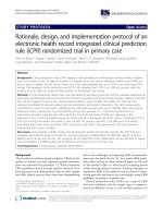
2.2.1 PWM TECHNIQUE (PULSE WIDTH MODULATION)
PWM is a signal that is generated by a digital integrated circuit. The signal of the
PWM are square clock pulses with the high logic level at high voltage level and the
low logic level at low voltage level (GND or 0V). The signal is high or low at any
time. To be easy for understanding, we will consider 5V PWM (5V is high level and
0V is low level):
Figure 2.1: PWM technique
6