NAVFAC P-433 Welding Materials Handbook_4 ppt
Bạn đang xem bản rút gọn của tài liệu. Xem và tải ngay bản đầy đủ của tài liệu tại đây (159.52 KB, 17 trang )
PREHEAT
(Continued)
Table 2-1 shows recommended preheat temperatures for
welding. Temperatures higher than those indicated on
this chart are sometimes required when hard-facing,
depending on the size and shape of the part and the type
of hard-facing alloy to be applied.
WELDING ON CAST IRON
Rebuilding and hard-facing of cast iron is not generally
recommended since it is extremely crack sensitive.
However, some cast iron parts, primarily those subject to
straight abrasion, are being successfully hard-faced.
Under any circumstances, cast iron parts require high
preheat temperatures, from 1000- 1200°F (dull red),
and must be slow cooled after welding. Weld deposits on
cast iron should be peened to help relieve stresses.
BUILDUP MATERIALS AND BASE METALS
Considerable differences exist between welding materials
used to buildup worn equipment and those used for
hard-facing overlays.
2-3
Prior to hard-facing, badly worn parts must be restored
with an appropriate buildup material to within 2/16 -
3/8 in. of their finished size. The buildup material
must have sufficient mechanical strength to sustain
structural requirements.
It must resist cold flowing,
mushing under high compressive loads and plastic
deformation under heavy impact. If the buildup
material doesn’t possess these properties, a hard-facing
overlay, which has comparatively little ductility, will
span for lack of support. In addition to these
mechanical requirements, a buildup material must be
compatible with the base metal and the hard-facing
overlay.
Use electrode on page 1-24 as the primary source and
electrodes on pages 1-5 and 1-3, in that order, as
alternate sources to rebuild carbon steel parts prior to
overlaying with hard-facing electrodes. When
hard-facing with the high alloy group, apply the
recommended hard-facing material before placing it in
service and do not allow it to wear more than 1/4 in.
(two layers) before hard-facing. If carbon steel parts
Simpo PDF Merge and Split Unregistered Version -
BUILDUP MATERIALS
AND BASE METALS
THICKNESS OF HARD-FACING DEPOSITS
(Continued)
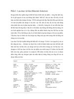
that are to be hard-faced with the high alloy group
A deposit of a hard-facing alloy that is too thick can
require buildup, it is vital that high interpass give you more problems than no deposit at all. In most
temperatures are maintained while observing the
cases, hard-facing materials should be limited to two
following procedures as illustrated in Figure 2-1. Use
layers; the first layer will produce an admixture with
weaving bead instead of stringer bead when applying
the base metal and the second layer will produce the
hard-facing. Limit single pass bead thickness to 3/16 desired wear-resistant surface.
inch. Use same technique for second layer. Avoid
severe quench.
To rebuild austenitic manganese steel parts, use the
electrode on page 1-29 as the primary source and the
electrode on page 1-27 as the secondary source.
WORKPIECE POSITIONING
You will get the job done quicker and more
economically if the part being hard-faced is positioned
for downhand welding. When down-hand welding is
not practical, select an electrode recommended for
all-position welding.
2-4
Simpo PDF Merge and Split Unregistered Version -
OSCILLATE ROD-
HARD-FACING
WEAVE, FIGURE 8
OVERLAY
OR HORSESHOE
FIGURE 2-1. Hard-Facing Techniques
2-5
Simpo PDF Merge and Split Unregistered Version -
TABLE 2-1. Metals Preheating Chart
Metal
Metal Recommended
Group
Designation
Preheat
PLAIN
Plain Carbon Steel - Below .20%C Up to 200°F
CARBON
Plain Carbon Steel - .20 30%C
200°F-300°F
STEELS
Plain Carbon Steel - .30 45%C 300°F-500°F
Plain Carbon Steel - .45 80%C 500°F-800°F
CARBON
Carbon Moly Steel 10 20%C
300°F-500°F
MOLY Carbon Moly Steel 20 30%C
400°F-600°F
STEELS Carbon Moly Steel 30 35%C
500°F-800°F
MANGANESE
STEELS
Silicon Structural Steel 300°F-500°F
Medium Manganese Steel
300°F-500°F
SAE T 1330 Steel
SAE T 1340 Steel
500°F-800°F
SAE T 1350 Steel 600°F-900°F
12% Manganese Steel
Usually not required
2-6
Simpo PDF Merge and Split Unregistered Version -
Metal
Group
HIGH
TENSILE
STEELS
TABLE 2-1. Metals Preheating Chart (Continued)
Metal
Designation
Manganese Moly Steel
Jalten Steel
Manten Steel
Armco High Tensile Steel
Double Strength #1 Steel
Double Strength #1 Steel
Mayari R Steel
Otiscoloy Steel
Nax High Tensile Steel
Cromansil Steel
A. W. Dyn-El Steel
Corten Steel
Chrome Copper Nickel Steel
Chrome Manganese Steel
Yoloy Steel
Hi-Steel
Recommended
Preheat
300°F-500°F
400°F-600°F
400°F-600°F
Up to 200°F
300°F-600°F
400°F-700°F
Up to 300°F
200°F-400°F
Up to 300°F
300°F-400°F
Up to 300°F
200°F-400°F
200°F-400°F
400°F-600°F
200°F-600°F
200°F-500°F
2-7
Simpo PDF Merge and Split Unregistered Version -
TABLE 2-1. Metals Preheating Chart (Continued)
Metal
Group
NICKEL STEELS
MEDIUM NICKEL
CHROMIUM STEELS
Metal
Designation
SAE 2015 Steel
SAE2115 Steel
2-1/2% Nickel Steel
SAE2315 Steel
SAE 2320 Steel
SAE 2330 Steel
SAE 2340 Steel
SAE3115 Steel
SAE 3125 Steel
SAE 3130 Steel
SAE 3140 Steel
SAE 3150 Steel
SAE 3215 Steel
SAE 3230 Steel
SAE 3240 Steel
SAE 3250 Steel
SAE 3315 Steel
2-8
Recommended
Preheat
Up to 300°F
200°F-300°F
200°F-400°F
200°F-500°F
200°F-500°F
300°F-600°F
400°F-700°F
200°F-400°F
300°F-500°F
400°F-700°F
500°F-800°F
600°F-900°F
300°F-500°F
500°F-700°F
700°F-l00°F
900°F-1100°F
500°F-700°F
Simpo PDF Merge and Split Unregistered Version -
TABLE 2-1. Metals Preheating Chart (Continued)
Metal
Group
MEDIUM NICKEL
CHROMIUM STEELS
MOLY BEARING
CHROMIUM
and
CHROMIUM NICKEL
STEELS
LOW CHROME (Cr)
MOLY (Me) STEELS
Metal
Designation
SAE 3325 Steel
SAE 3435 Steel
SAE 3450 Steel
SAE 4140 Steel
SAE 4340 Steel
SAE 4615 Steel
SAE 4630 Steel
SAE 4640 Steel
SAE 4820 Steel
2% Cr. - 1/2% Mo. Steel
2% Cr. - l/29% Mo. Steel
2% Cr. - 1% Mo. Steel
2% Cr. -1% Mo. Steel
Recommended
Preheat
900°F-1100°F
900°F-1100°F
900°F-1100°F
600°F-800°F
700°F-900°F
400°F-600°F
500°F-700°F
600°F-800°F
600°F-800°F
400°F-600°F
500°F-800°F
500°F-700°F
600°F-800°F
2-9
Simpo PDF Merge and Split Unregistered Version -
TABLE 2-1. Metals Preheating Chart (Continued)
Metal
Metal
Recommended
Group
Designation
Preheat
MEDIUM CHROME (Cr)
5% Cr. - 1/2% Mo. Steel
500°F-800°F
MOLY (Me) STEELS
5% Cr. - 1/2% Mo. Steel
600°F-900°F
8% Cr. - 1% Mo. Steel
600°F-900°F
PLAIN HIGH
12-14% Cr. Type 410
300°F-500°F
CHROMIUM (Cr)
16-18% Cr. Type 430
300°F-500°F
STEELS
23-30% Cr. Type 446
300°F-500°F
HIGH CHROME (Cr)
18% Cr. - 8% Ni. Type 304
Usually does not require
NICKEL (Ni)
25-12 Type 309
preheating but it maybe
COLUMBIUM (Cb)
25-20 Type 310
desirable to remove
STAINLESS STEEL
18-8 Cb. Type 347
chill.
18-8 Mo. Type 316
18-8 Mo. Type 317
2-10
Simpo PDF Merge and Split Unregistered Version -
TYPES OF WEAR
Abrasion
A grinding action caused by abrasive solids sliding,
rolling or rubbing against a surface. Referred to as
gouging when combined with high compressive loads,
Impact
A blow or series of blows to a surface, resulting in
fracture or gradual deterioration,
Heat
Softens metallic structures and may accelerate
chemical attacks like oxidation and scaling; however,
it may cause phase changes that increase hardness and
brittleness.
2-11
Simpo PDF Merge and Split Unregistered Version -
THE DIFFERENCE BETWEEN CROSS-
Corrosion
CHECKING AND CRACKING
Deterioration of metal by chemical or electrochemical
Deposits made with high allov electrodes should check
reaction with its environment.
RECOMMENDED AMPERAGE AND POLARITY
.
on the surface. The check pattern is highly desirable
as it reduces residual stresses. Without checking, the
residual (or locked-in) stresses when combined with
service stresses can reach a magnitude greater than the
tensile strength and result in deep cracks or spalling
(Figure 2-2). If checking does not occur naturally, it
must be induced to avoid future failure. For example,
as heat builds up in large parts, less cross checking will
take place. To rectify this, forced checking can be
accomplished by sponging the deposit with a wet cloth
or by spraying the surface with a fine water mist.
Checking may also be accelerated during the cooling
period by occasionally striking the deposit with a
hammer. If a check-free deposit is necessary, use a
softer alloy and observe preheat and postheat
requirements.
Weld data showing recommended amperage and
polarities is listed in Section 1 on each page for every
electrode.
2-12
Simpo PDF Merge and Split Unregistered Version -
OXY-MAPP HARD-FACJNG
General Rules
1.
2.
3.
4.
Use the oxy-MAPP method for hard-facing thin
cutting edges; electric arc welding is more apt to
bum through. oxy-MAPP is also preferred where
minimum dilution is required.
Most small parts made of low-, medium-or
relatively high-carbon steel can be hard-faced by
the oxy-MAPP process. The hard-facing of cast
iron is not recommended.
Use a tip approximately four sizes larger than that
ordinarily used to deposit a mild steel rod of the
same diameter.
Where possible, use a jig to quickly position the
part for downhand welding, especially when the
part must be turned two or more times. This will
save time and gas.
5. Lineup smaller parts like ditcher teeth or coal
cutter bits in a row for easy pm-heating during
welding.
6. Clean all areas to be hard-faced with a grinding
wheel regardless of whether the part is new or
used. Grinding helps eliminate pin holes and
makes it easier to apply the hard metal. The
ground surface should always extend beyond the
hard metal deposit. In other words, if the hard
metal deposit is to be 1 in. wide, the ground area
should be 1-1/2 in. wide.
7. When you hard-face any type of an edged tool you
increase its thickness. It is therefore desirable to
draw out or sharpen all types of edged implements,
new or used, before the hard metal is deposited.
2-13
Simpo PDF Merge and Split Unregistered Version -
FIGURE 2-2. Cross-Checking and Cracking Comparison
2-14
Simpo PDF Merge and Split Unregistered Version -
FLAME ADJUSTMENTS
Three basic flame adjustments are used to deposit
hard-facing rods.
The excess MAPP flames (3X and 4X as shown in
Figure 2-3) are used to:
(1) Spread the heat to minimize possible
burn-through on thin edges;
(2) add excess carbon to the skin of the part being
hard-faced.
The additional carbon lowers the melting point and
sweating temperature of the part, facilitating the
deposit of the hard-facing alloy.
FIGURE 2-3. Flame Adjustments for
Hard-Facing.
2-15
Simpo PDF Merge and Split Unregistered Version -
Earthmoving and Heavy Construction Equipment
FIGURE 24. Tractor Parts and Accessories
2-16
Simpo PDF Merge and Split Unregistered Version -
TRACTOR PARTS AND ACCESSORIES
(See
Figure 2-4)
(NOTE: TO PREVENT DAMAGE FROM
ELECTRIC
AL ARC. REMOVE BEARINGS
BEFORE WELDING)
Track Rollers
Primary Electrode: Page 1-24
Alternate Electrodes: Pages 1-5, 1-3
Welding Procedures: Mount roller on jig for
downhand welding. Apply transverse beads on
running face and flange (Figure 2-5).
FIGURE 2-5. Hard-Facing Track Rollers
Tractor Idlers
Primary Electrode: Page 1-31
Alternate Electrodes: Pages 1-5, 1-3
Welding Procedures: Mount idler in jig for downhand
welding. Beads are often applied transversely (Figure
2-6).
FIGURE 2-6. Hard Facing Tractor Idlers
2-17
Simpo PDF Merge and Split Unregistered Version -
TRACTOR PARTS AND ACCESSORIES
(Continued)
Tractor Rails
Carbon Steel
Primary Electrode: Page 1-24
Alternate Electrodes: Pages 1-5, 1-3
Welding Procedures: Do not rebuild rails until they
have worn to recommended service limits. Buildup
outside edges to same level as center. Apply wash
passes 1/2 in. wide until entire surface is covered.
Work alternately on four links to avoid overheating.
Use only buildup materials; do not hardface (Figure
2-7).
FIGURE 2-7. Rebuilding Tractor Rails
2-18
Simpo PDF Merge and Split Unregistered Version -
TRACTOR PARTS AND ACCESSORIES
(Continued)
Top Carrier Rolls
(NOTE: DO NOT USE BUILDUP ELECTRODE ON
CAST IRON)
Cast Iron
Carbon Steel - Follow same procedure with
Primary Electrode: Page 1-14
recommended alloys, but preheat is not necessary
(Figure 2-8).
Carbon Steel:
Primary Electrode: Page 1-24
Alternate Electrodes: Pages 1-5, 1-3
Welding Procedures: Cast Iron - Mount roller on jig
for downhand welding after bushings have been
pressed out and surfaces cleaned. Preheat part to 1000
- 1200°F. Play burner flame on roll during entire
welding operation. Apply two layers of electrode on
page 1-14 in wide transverse beads; weld alternately
on opposite ends of roll. Slow cool in asbestos or lime
box.
FIGURE 2-8. Hard-Facing Top Carrier Rolls
2-19
Simpo PDF Merge and Split Unregistered Version -