Inspection of Vertical Transportation Equipment_6 ppt
Bạn đang xem bản rút gọn của tài liệu. Xem và tải ngay bản đầy đủ của tài liệu tại đây (1.47 MB, 27 trang )
Check for evidence of excessive deflection (over 1/4 inch) by observing the rail with car
operating. Note that rails extend from the bottom of hoistway to top sufficiently to prevent guide
shoes from running off the rails.
6.4.4 Outside The Hoistway Inspection
6.4.4.1 Hoistway. Inspection outside the hoistway should verify an adequate hoistway
enclosure. Provisions should provide protection from accidental contact with the moving car or
counterweight (if provided) and prevent entry into the hoistway when the car is away from the
landing. A complete hoistway enclosure is not required, but where provided for safety, it should
be solid or reject a 1" diameter ball.
6.4.4.2 Hoistway Entrance. The full width of each landing opening must be protected to full
height (or 7'-0" whichever is less) by doors or gates. Open work must reject a 1" diameter ball.
Inspection of landing closures should note damage, rust and critical wear in moving parts and
contact points. Open and close each hoistway door or gate with the car at the floor. It should
operate freely; all components should be clean and securely fastened. Try to open each door or
gate with the car away from the floor; it should not open. Try to run the car with each door open;
the car should not run. Operation of the hoistway entrance lock and contact devices is a critical
safety element. Each lock should be carefully examined. It should be securely fastened, cleaned
and aligned so that the contact and lowering mechanisms are properly related.
6.4.4.3 Operation. Actuate controls at each floor. Fixtures should be securely fastened, buttons
should operate freely and controls should call the elevator to the floor if car and hoistway
doors/gates are closed properly.
6.4.5 Machine Room And Machine Spaces Inspection
6.4.5.1 Housekeeping. Machine room and equipment cleanliness is of primary concern with this
type elevator. Location may be remote and used infrequently. Maintenance may be intermittent.
Generally observe the machine room access, lighting, ventilation, cleanliness and guards
preventing accidental contact with moving parts. Any unsafe condition should be noted. Only
material and equipment necessary for elevator operation and maintenance should be stored in the
machine room.
6.4.5.2 Hoist Machine. Inspect the machine and sheave fastenings to make certain they are
secure. Check for wear, gear play and leaking lubricant. Operate the elevator. Check the brake
operation. Inspect brake pads for wear and note that the brake is electrically released and
mechanically applied.
6-15
Simpo PDF Merge and Split Unregistered Version -
6.4.5.3 Governor. Type A safety devices are required on traction and winding drum elevators.
Check governors for proper maintenance. All parts should operate freely, but not have excessive
play. Safety jaws should be clean and free from lubricant.
6.4.5.4 Slack Cable or Chain Device. Check the slack cable/chain device. Power should be
removed from the elevator system if the suspension means breaks or goes slack for any reason.
6.4.5.5 Clearance. Observe the machine space and all equipment for general cleanliness and
unsafe conditions. Space should be adequately lighted and ventilated. Equipment should be
guarded.
6.4.5.6 Controls. Check control panels. Equipment must be grounded and properly fused. Look
for worn or burnt components, broken or abraded insulation and wiring, loose connections and
disconnected wires. The mainline switch should be arranged so that it can be locked when
disconnected.
6.4.6 Inside The Hoistway Inspection
6.4.6.1 Buffers. Pits with buffers and bottom runby conforming to regular traction elevators are
required.
6.4.6.2 Pit. Pit should be clean and dry, free of stored material. Pit equipment should be clean
and free of rust. Check operation of the light switch, light and stop switch.
6.4.6.3 Hoistway. Only pipes or wiring related to elevator operation should be located in the
elevator hoistway. Check that all equipment is securely fastened, clean, properly lubricated and
not rusted. Check hoist ropes for uniform tension, breaks and wear. Cables must be properly
lubricated and free of rust and red rouge.
6.4.6.4 Counterweights. Counterweights must be guarded in the pit and in the hoistway
wherever accidental contact might occur. Protection must reject a 1" diameter ball. Normal rules
apply if occupied space is located below the pit.
6.4.6.5 Car Safety Device. Visually check car bottom for cleanliness. Observe safety device to
determine that parts are free to operate.
6.4.7 Periodic Inspection And Tests
The A17.1 Code indicates that special purpose elevators are subject to routine and periodic
tests (Rule 1010.6). Procedures and methods described in the A17.2 Manual for electric and
hydraulic elevators should be applied when inspecting special purpose elevators.
6-16
Simpo PDF Merge and Split Unregistered Version -
Testing data should be specifically documented on the inspector's report that these test have been
performed and the dates the tests were made.
6.5 HANDICAPPED LIFTS
6.5.1 Scope
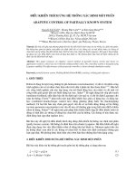
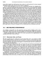
Part XX of the A17.1 Code covers Inclined Chairlifts and Inclined and Vertical Wheelchair
Lifts. These devices are intended for use by the physically handicapped to facilitate access
through architectural barriers. They are an economical means of providing access especially in
existing structures. Figures 6-4 through 6-7 show typical application of these devices. The Code
does not presently specify a frequency for inspecting these devices. Location of the device
should actually be used to make this determination. Units located outside will need inspections
more frequently than those inside. It is recommended that all devices be inspected at least
every 6 months.
6.5.2 Platform Inspection
6.5.2.1 Platform. Examine the complete assembly with the platform at the lowest level.
Determine that all fastenings are secure and that no components are damaged or bent. Note that
all surfaces are properly painted or otherwise protected. Check guide channels to be sure they are
smooth, not worn or bent and properly greased.
6.5.2.2 Car Gate. Examine gate locks at both levels. Verify that they are securely fastened,
properly aligned, operating freely, clean and free from corrosion.
6.5.2.3 Operation. Open the landing gate, actuate the car control to verify that it will not move.
Verify this same function with the car gate open. Close all gates and press the "up" control. Car
should start in the up direction but stop if pressure on the control is released. During the up
trip verify the following:
a. That protective side screens are properly positioned and secure.
b. That there is no obstruction that might strike a riding passenger.
c. That the ride is smooth and without bumps or jerks.
The platform should stop automatically at the upper landing. verify proper stopping accuracy.
Open car and landing gate and press "down" operational control. The platform should not move.
6-17
Simpo PDF Merge and Split Unregistered Version -
Simpo PDF Merge and Split Unregistered Version -
Simpo PDF Merge and Split Unregistered Version -
Simpo PDF Merge and Split Unregistered Version -
Simpo PDF Merge and Split Unregistered Version -
Close the gates and return to the lower landing. The platform should stop automatically at the
lower level. Open the car and landing gate to verify proper stopping accuracy. Verify proper
operation of the alarm bell.
6.5.2.4 Access Ramp. Some units have an automatic access ramp which rises and locks during
travel. If the unit has such a device, verify that it is suitably adjusted and operates properly.
6.5.3 Landing Inspection
6.5.3.1 Landing Gates. Examine landing gates. Verify that all fastenings are secure, that the
gates swing freely and are not damaged. Gates should be clean and properly painted. Normally,
each landing will have a ramp integral with the landing gate supporting assembly. Check this
ramp for proper fastening and fit. Be sure both ends are flush with adjacent floor or
members and will not obstruct wheel chair or present a tripping hazard to a pedestrian.
6.5.3.2 Operation. With the platform at the lower level, check that the upper level gate cannot
be opened. Actuate the upper level control and verify proper operation. Check side screens for
damage or corrosion. They should be clean and properly painted. Listen while the unit is
operating, for abnormal sounds which might indicate problems with motor, screw drive or
screw drive bearings. Attempt to open the lower landing gate. It should not open with the
platform at the upper level. Actuate the landing control and verify proper operation.
6.5.3.3 Platform. With the platform at the top level, inspect the space under the platform. It
should be clean. Verify that inside surfaces of the side screens are clean and properly painted.
6.5.4 Machine Space Inspection
6.5.4.1 Access. Access to the machine space is normally accomplished by removing a protective
panel. Most units have panels that lift and rotate to remove. Before removing the access panel
disconnect the power supply with the platform at the lower level.
6.5.4.2 Controls. Check the electrical control panel. Power should be provided to the panel
from a lockable electrical disconnect device located adjacent to the unit. The power circuit
should be fused at some point. Wiring should be properly fastened with no loose connections or
unsecured wires. Verify that the unit is properly grounded. Replace the junction box cover.
6-22
Simpo PDF Merge and Split Unregistered Version -
6.5.4.3 Hoist Machine. Normal motors are usually AC type with sealed bearings. Check the
motor and drive sheave for evidence of abnormal condition or corrosion. Connection to the
screw drive will generally be "V" belts. Inspect belts for wear and proper tension (proper tension
is about 1/2" deflection at the center with medium thumb pressure). Inspect the screw and nut
(ball). The screw should be clean, lightly greased and show no sign of damage or abnormal
wear. Bearings at the top and bottom of the screw should be properly greased. Check all
connections to be sure they are secure. Verify the machine space is clean and properly painted
with no corrosion. Replace the cover and restore power.
6.6 INCLINED ELEVATORS
6.6.1 Introduction
The rules of Part XVII are applicable to inclined lifts intended for public use. An inclined
elevator is defined as an elevator where the angle of inclination is less than 70 degrees from
horizontal. The Code allows inclined elevators to be driven by traction, winding drum or screw
type drives. The majority of inclined elevators are traction drive type with components
comparable to a standard elevator. Entry will be protected by some type of enclosure; some type
of cab will exist and controls will be provided at landings and inside the car. Your inspection
therefore should be based on principles for examining normal elevator equipment. Two
characteristics of inclined elevator installations should be kept in mind during an inspection.
First, the guide system is usually supported on an elevated structure without a hoistway enclosure
between landings. While inspecting the guidepath, the possibility of falling is substantially
greater than in a conventional elevator hoistway. Second, the guidepath may consist of open
structural supports not unlike an escalator truss. Special care must be taken to secure stable
footing.
6.6.2 Hoistway
Hoistway enclosures must be fire rated only if fire resistant construction of the buildings they
serve is penetrated. If the lowest surface of the inclined elevator guides or moving components
are at least eight feet above the surface below, no enclosure is required. Non fire resistive
enclosures must be at least seven feet high and reject a ball 3/4 inch in diameter. The enclosure
must be located at least 6 inches from moving components. If the enclosure is at least 36 inches
from moving components, the open work can be such that a two inch diameter ball will be
rejected. Openwork enclosure areas adjacent to entrances must reject a ½ inch diameter ball.
6-23
Simpo PDF Merge and Split Unregistered Version -
Enclosures must be supported and braced adequately so that they will not deflect more than 2
inches when a force of 100 pounds is applied to any four square inches. Where an elevated
guideway crosses over any passageway, the underside of the guideway must be enclosed.
6.6.3 Inside The Car Inspection
Division 101 of A17.2 Manual describes the various inspections that are made from inside the
car on traction elevators. These should be followed with the special considerations noted
hereafter.
6.6.3.1 Car Enclosure. (Item 101.1). Tops are not required unless equipment is placed or
installed so that servicing from the top of the car is required. Determine that all car components
are solidly fastened and braced. Collapsible car gates are not allowed. Hinged doors should
only open into the car. Benches and seats are common. The net area inside the car may be
increased as much as 50% over normal passenger elevator area for a given capacity rating to
compensate for permanently located and nonfolding benches or seats. The overall enclosure
should not have loose or missing components or hardware. When something is missing or loose,
total safety is compromised. Where the car sill is more than six feet above guard at any point in
travel and the hoistway enclosure is more than six inches away from the car door anywhere in the
car travel, the car door must have an interlock which prevents opening the door from inside the
car, except when the car is within the leveling zone at any floor.
6.6.3.2 Operating and Control Devices. (Item 301.3). Operation can be automatic or
continuous pressure. All operating and signalling devices should be securely fastened and
operating properly. The signalling devices are important to elevator safety. If the inclined
elevator is open to weather, all exposed fixtures should be of weatherproof type.
6.6.4 Outside The Car Inspection
Division 102 of the A17.2 Manual describes the various inspections that are to be made from
outside the hoistway on traction elevators. Hoistway entrances are the major items that are
examined at this time. Items 100.1 to 100.5, as well as item 103.12 and 103.13, apply to the
hoistway enclosure and doors. These items should be followed, with the special considerations
noted hereafter.
6.6.4.1 Hoistway Access. Inclined elevators, without fully enclosed hoistways, are not required
to have hoistway access switches or parking devices. Means to operate the elevator from outside
the car during inspection, adjustment, maintenance and repair are required. The means for
transferring control to the exterior device may be in the car or at the controller.
6-24
Simpo PDF Merge and Split Unregistered Version -
6.6.4.2 Guideway Support Structure. An important inspection made from outside the hoistway
is the check of the guideway support structure. This should be visually inspected for the entire
length of travel. Carefully note loose fastenings, damaged components and indications of
deterioration. Observation of the support with a fully loaded and running car may indicate
structure deficiency by flexing or bending of members. Most inspections of roping car and
counterweight safety devices, stopping devices, buffers, etc. which are included in Division 103
and 105 of the A17.2 Manual (Inspection Made From Top of Car and Pit) will be made from the
guidepath or from the car, depending upon specific equipment design. Note that spring buffers
may be used up to a speed of 125 f.p.m. Carefully note traveling cables, suspension and
compensation ropes. They must be suitably protected against abrasion and fouling. Components
subject to corrosion on exterior installations shall be weatherproofed by acceptable means of
protection and fixtures shall be weatherproof type.
6.6.5 Machine Spaces And Machine Room Inspection
Division 104 of the A17.2 Manual describes the various inspections which are made in the
overhead machinery spaces and machine room. Use Division 104 to make machine room
inspections of inclined elevators with special consideration noted hereafter.
6.6.5.1 Slack Rope Device. A broken (slack) rope device is required on both the car and
counterweight sides of the drive machine of the guideway if the inclination is less than 35
degrees from the horizontal. Verify the presence and proper operation of the device if the
guideway incline is less than 35 degrees.
6.6.5.2 Safety Device. If the inclination exceeds 35 degrees from the horizontal, a type A safety
device may be used if speed does not exceed 125 f.p.m. Type C safety may be used if speed does
not exceed 175 f.p.m. In any event, rope driven governors are not required. Check safety device
type, based on car speed, and verify that the proper type has been used.
6.6.5.3 Drive Sheave or Drum. Traction or drum sheave wear is usually detected by finding
metal particles under the sheave. However, an inspector should watch for the signs that lead to
wear before results are seen. The major cause of wear is uneven rope tension. The sheave is
designed to carry the load spread over all the ropes. When one is under more tension than the
others, this load is transferred to the tighter rope. This can usually be seen by laying a straight
edge across the ropes in the drive sheave grooves. All rope should touch the straight edge.
Ropes that do not touch indicate uneven tension or possible sheave wear. Mistakes are found in
the type of size of ropes used. Check date tags to verify proper application.
6-25
Simpo PDF Merge and Split Unregistered Version -
6.6.5.4 Guards. Many times guards are removed to service equipment and in haste are not
returned to their proper place. A guard sitting off to the side is not doing its job and could result
in a painful accident.
6.6.5.5 Gears and Bearings. A thorough check of the hoistway machine gears and bearings
should be made on each inspection trip. Problems in these areas do not happen overnight. If
found early, they can greatly reduce repair cost and time. Bearing problems are detected by
sound and/or heat. Gear problems are detected by examining wear pattern on the gear. This will
show that the gear is not properly aligned with the worm causing contact in an improper position,
or that the gear is bottoming or contacting the worm shaft. Excessive heat damage, most likely
caused by low oil or break down of oil, can also be detected. It is indicated by pock marks in the
face of the gear tooth or teeth.
6.6.5.6 Hoist Motor. It is very important to check the hoist machine motor. Commutator or slip
ring damage Are indications that something is not right and needs immediate attention. Become
very familiar with these signs and be constantly on the look-out for them. Elevator performance
is directly related to good electrical continuity throughout the commutator or slip rings. Also,
heat is always a major concern and is a problem indicated. The source of the heat should be
investigated and corrective action recommended. Motors should be kept clean to assure proper
air passages that are needed for cooling. Connections not properly made may result in poor
electrical conduction and points of resistance. This condition creates heat. Improper adjustments
can force motor windings to carry more current, which produces heat, thus causing insulation
deterioration.
6.6.5.7 Brake. Closely examine both the mechanical actions of the brake and the electrical
components. The A17.2 Manual addresses the examination of the mechanical action. As for the
electrical components, the brake coil leads, connections, and windings should be examined to
check insulation conditions and physical connections. In addition, many brakes have electrical
contacts that are used in various control functions. These should be checked to assure proper
contact operation, insulation on wire and contacts, and condition of connections. Many control
systems, by design, stop the elevator electrically when it reaches the floor, which allows the
brake to set. This is done to prevent a bump on stopping, which is caused when the brakes set.
Brake operation should be checked, where applicable, to see that the feature is working properly.
6.6.5.8 Controls. The A17.2 Manual outlines a complete inspection of the control equipment. A
good preventative maintenance program on the control equipment will greatly reduce shut
downs.
6-26
Simpo PDF Merge and Split Unregistered Version -
6.6.5.9 Housekeeping. The overall machine room should never be overlooked. The A17.2
Manual lists each area to be checked. It reduces the possibility of accidents and has a direct
impact on fire safety. Proper ventilation is required to keep equipment operating. Inclined
elevators are often exterior to buildings and subject to weather. All components should be
checked for rusting and other deterioration. Provisions should be provided for machine room
heating to a minimum of 40 degrees F. Machine room access door hardware is very often found
not meeting all requirements of the A17.1 Code. In addition, Navy policy is that the machine
rooms have controlled access areas to be secured by lock and key or combination locks. Machine
rooms and machinery spaces are not to be used for storage of non-elevator related items.
Absolutely no flammable items are permitted.
6.6.5.10 Machine Room Access. Access to machine room and machinery spaces must always be
checked. Not only to assure that the usual ladders, stairs, lights, railings, etc. are kept in first
class condition, but to be sure that the access is not infringed on by building changes. Safety may
be directly dependent on rescue personnel getting to the elevator equipment in a hurry.
6.6.6 Periodic Inspection And Tests
6.6.6.1 Scope. The A17.1 Code indicates that inclined elevators are subject to routine and
periodic tests (Rule 1010.7) at intervals not less than 6 months. Procedures and methods
described in the A17.2 Manual for electric elevators should be applied when inspecting inclined
elevators. Testing data should be specifically documented on the inspector's report that these
test have been performed and the dates the tests were made.
6.6.6.2 Governor and Safety. Division 111 of the A17.2 Manual covers inspection of governors.
Division 112 of the A17.2 Manual covers inspection and test of the car and counterweight
safeties. This is a no load, slow speed test of the safety equipment. It is done to exercise the
equipment to assure its proper operation. Full load tests are outlined in Division 113.
6.6.6.3 Buffers. Division 114 and 115 of the A17.2 Manual covers buffer tests.
6.6.6.4 Normal and Final Limits. Division 116 of the A17.2 Manual covers the operational test
of normal and final terminal stopping devices. The limits only receive a functional test during
routine inspections. The annual test requires setting conditions that will require the limits to
operate as they would if conditions warranted.
6-27
Simpo PDF Merge and Split Unregistered Version -
CHAPTER 7
ESCALATORS
7.1 INTRODUCTION
NOTE: Paragraphs identified with a vertical line in the left margin are inspections that should
be made by Inspectors only.
7.1.1 Scope
The inspection of escalators included in this chapter is not only an inspection of all safety
related functions, but is also an inspection to determine the condition of the equipment and
identify areas that need improvement. Proper maintenance is needed to keep the escalator
operating. When preventive maintenance is lacking, shut downs will occur. Part III of
the ANSI/ASME A17.2 Inspector's Manual for Elevators and Escalators addresses the safety
aspect of the inspection of escalators. In this chapter we will identify the specific Division of
Part III which relates directly to the inspection procedure being followed in this text. It is
intended that each noted division should be reviewed as it is identified and suggested
procedures followed. The maintenance and performance considerations of the inspection will be
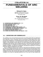
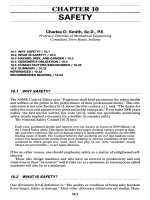
addressed in the following text. See Figures 7-1, 7-2, and 7-3 which show various escalator
arrangements with component names that will be used in this chapter.
7.1.2 Performance Criteria
As was stated previously, the purpose of this type of inspection is to review the entire
escalator installation; this includes measuring the operation of specific elements of the system
against standards which have been established either by national codes or engineering practice
common to the escalator industry. The components of the system selected for testing are those
most directly related to safe operation of the escalator and the overall installation, although some
items, such as speed of the escalator, are related to the efficiency of the operation and grade of
service provided. The following is an explanation of the areas that should be tested and
criteria to use for evaluating this performance.
7.1.2.1 Escalator Operating Speed. Escalator operating speed is measured with a tachometer
held against the deck while riding on the unit. operating speed should be maintained at a level of
plus or minus 5% of the speed under any load condition in both directions of travel. A second
speed test should be performed by holding a tachometer on the handrail while standing at the
top or bottom landing. Both handrails and the step speeds should be very close. A speed
variation might indicate a condition of handrail slip.
7-1
Simpo PDF Merge and Split Unregistered Version -
7-2
Simpo PDF Merge and Split Unregistered Version -
7-3
Simpo PDF Merge and Split Unregistered Version -
7-4
Simpo PDF Merge and Split Unregistered Version -
7.2 ROUTINE INSPECTION
7.2.1 Scope
Division 300 of the A17.2 Manual covers inspections made on the escalator exterior. This
section of the A17.2 Manual is quite complete and covers the majority of the items to examine.
However, the inspector must also check to see that all operating equipment is functioning in its
intended manner and that the appearance is acceptable to the rider.
7.2.2 Balustrades And Guards
Note any cracked or broken balustrade panels or ceiling intersection guards. Also note any
screws or fasteners used to hold panels or molding that are not flush or that have burrs. Ceiling
intersection guards should conform to dimensions shown in Figure 7-4. Check to see that
anti-slide devices are provided on decks where required for equipment installed under the 1981
and later editions of the Code.
7.2.3 Handrails
The handrails should be inspected, paying close attention to all splices and joints. Splices or
joints that open up can cause severe finger pinch as the handrail goes around the newel.
Handrails should move in the same direction and at substantially the same speed as the steps.
Handrail tension should be checked by grasping a handrail, on a down running escalator, from
the top landing. If it takes a great amount of effort to stall the rail, the tension is correct. If the
handrail can be easily stalled then it should be readjusted.
7.2.4 Step Treads And Risers
The escalator step treads and risers should be checked for broken corners, worn surfaces, oil
or debris. They should also be checked for excessive play in both directions of travel and from
side to side. Check clearance on units without cleated step risers (installed prior to 1971 edition
of the code). A clearance in excess of 5/32" may indicate worn chain pins and bushings and
require step chain replacement.
7.2.5 Combplates
Inspect the combplate and note any damaged or missing combplate teeth. The combplate
teeth should mesh evenly with the step-treads and the bottom of the teeth should be below the
upper surface of the steps. Damaged combplate teeth are very hazardous and should be replaced
immediately.
7-5
Simpo PDF Merge and Split Unregistered Version -
Simpo PDF Merge and Split Unregistered Version -
7.2.6 Illumination
Determine whether lighting at the landing and for the entire step run is adequate and in
accordance with local codes and ordinances for stairways. If combplate lights are furnished they
should all be in working order. Two green step demarcation fluorescent lamp fixtures, at each
landing, are required on equipment installed under the 1978 and later editions of the code.
7.2.7 Caution Signs
Caution signs should be located at the top and bottom landings for escalators installed under
the 1981 and later editions of the Code, although it is suggested that signs be recommended on
all escalators. See Figure 7-5. The sign should be readily visible to the boarding passengers and
include the following wording:
"CAUTION"
"PASSENGERS ONLY"
"HOLD HANDRAIL"
"ATTEND CHILDREN"
"AVOID SIDES"
The sign shall be standard for all escalators and shall be identical in format, size, color, wording,
and pictorials as shown is Figure 7-6. The sign shall be durable and have a maximum thickness
of 1/4" (6.3 mm), with rounded or beveled corners and edges.
7.2.8 Operation
Check the escalator movement in each direction of travel for a smooth operation. Note any
excessive noise or vibration and its location if possible. Check each emergency stop button in
each direction and observe stopping distance.
7.2.9 Skirt Obstruction Device
Physically trip the switch for the skirt obstruction devices. Use a nonmetallic probe between
the step and riser. This check can also be done after steps are removed for the interior inspection.
See Figure 7-7. Actuation should cause the opening of the power circuit to the driving machine
motor and brake.
7.2.10 Skirt To Step Clearance
Check the skirt panel for excessive clearance. See Figure 7-8. This can be done with a rule,
feeler gauges or commercially available devices made especially for this purpose. The clearance
between the step tread and the adjacent skirt panel is required to be not more than the distances
noted in ITEM 300.4 of the A17.2 Manual.
7-7
Simpo PDF Merge and Split Unregistered Version -
7-8
Simpo PDF Merge and Split Unregistered Version -
7-9
Simpo PDF Merge and Split Unregistered Version -
7.2.11 Start Switch
Check the key-operated switch in the run position. If the key can be left in the run position or
removed in the run position, check that the emergency stop buttons will function properly and the
escalator will not restart when the emergency stop buttons are released. Where automatic
starting devices are provided, check that they are nonfunctional after the emergency stop buttons
are released.
7.3 PERIODIC INSPECTION AND TESTS
7.3.1 Scope
Division 310 of the A17.2 Manual covers operational inspections and tests. It is required that
these inspections and tests must be performed every 12 months.
7.3.2 Machinery Space
Permanent electric lighting and a 20 Amp ground type 110V duplex receptacle shall be
provided in every remote machine room. The illumination shall be not less than 10 foot candles
at the floor level. The lighting control switch shall be located within easy reach of the access to
such rooms. Where practical, the light control switch shall be located on the lock jamb side of
the access door. Where the machine is located in the truss, a permanent 20 Amp grounding type
110 V duplex receptacle accessibly located within the machine area of the truss shall be provided
to accommodate a drop cord light. Determine whether the machinery space is clean and free of
oil and debris.
7.3.3 Controls
Examine controller (See Figure 7-9) visually to determine that it is clean and that contacts of
magnetically operated contactors and relays and the electrical connections thereto are in good
condition. Determine that the fuses are in place and have not been jumped or otherwise tampered
with. Where there is more than one driving machine in a room, check that each disconnect
switch or circuit breaker is numbered to correspond to the number of the driving machine which
it controls. Visually check the condition of the mechanical brake, if possible.
7.3.4 Wiring
All electrical wiring should be checked for damage. Many times conductors and conduits have
become damaged when working in the area. This must be constantly inspected to maintain a safe
environment.
7-10
Simpo PDF Merge and Split Unregistered Version -
7-11
Simpo PDF Merge and Split Unregistered Version -
7-12
Simpo PDF Merge and Split Unregistered Version -