Simultaneous carbon and nitrogen removal accompanied by energy recovery from wastewater in a coupled microbial fuel cells system
Bạn đang xem bản rút gọn của tài liệu. Xem và tải ngay bản đầy đủ của tài liệu tại đây (4.32 MB, 119 trang )
SIMULTANEOUS CARBON AND NITROGEN REMOVAL
ACCOMPANIED BY ENERGY RECOVERY FROM
WASTEWATER IN A COUPLED MICROBIAL FUEL CELLS
SYSTEM
BY
NGUYEN HOANG DUNG
A DISSERTATION SUBMITTED IN PARTIAL FULFILLMENT OF
THE REQUIREMENTS FOR THE DEGREE OF DOCTOR OF
PHILOSOPHY (ENGINEERING AND TECHNOLOGY)
SIRINDHORN INTERNATIONAL INSTITUTE OF TECHNOLOGY
THAMMASAT UNIVERSITY
ACADEMIC YEAR 2022
Ref. code: 25656222300219VQS
THAMMASAT UNIVERSITY
SIRINDHORN INTERNATIONAL INSTITUTE OF TECHNOLOGY
DISSERTATION
BY
NGUYEN HOANG DUNG
ENTITLED
SIMULTANEOUS CARBON AND NITROGEN REMOVAL ACCOMPANIED BY
ENERGY RECOVERY FROM WASTEWATER IN A COUPLED MICROBIAL
FUEL CELLS SYSTEM
was approved as partial fulfillment of the requirements for
the degree of Doctor of Philosophy (Engineering and Technology)
on June 26, 2023
Chairperson
(Professor Nipon Pisutpaisal, Ph.D.)
Member and Advisor
(Professor Sandhya Babel, D.Tech.Sc.)
Member
(Associate Professor Rachnarin Nitisoravut, Ph.D.)
Member
(Associate Professor Paiboon Sreearunothai, Ph.D.)
Member
(Associate Professor Jenyuk Lohwacharin, Ph.D.)
Member
(Warunsak Liamlaem, Ph.D.)
Director
(Professor Pruettha Nanakorn, D.Eng.)
Ref. code: 25656222300219VQS
(1)
Dissertation Title
SIMULTANEOUS
CARBON
AND
NITROGEN REMOVAL ACCOMPANIED BY
ENERGY
RECOVERY
WASTEWATER
IN
A
FROM
COUPLED
MICROBIAL FUEL CELLS SYSTEM
Author
Nguyen Hoang Dung
Degree
Doctor
of
Philosophy
(Engineering
and
Technology)
Faculty/University
Sirindhorn International Institute of Technology/
Thammasat University
Dissertation Advisor
Professor Sandhya Babel, D.Tech.Sc.
Academic Years
2022
ABSTRACT
For over a decade, microbial fuel cell (MFC) has received much attention as a
pioneering technology for wastewater treatment, owing to its ability to generate
electricity from organic matter. However, most wastewater has the presence of nitrogen
and the requirement to remove nitrogen as a contaminant has caused limitations in
energy recovery from organic carbon. Despite the advantages of integrating biological
nitrogen removal (BNR) into MFC and the promising results in organic carbon removal,
achieving high nitrogen removal efficiency while optimizing energy recovery from
organic matter remains a challenge. It is difficult to select an external resistance (ER)
value that satisfies both goals. The chambers of a stacked MFC system can be
sequencing-batch operated to achieve specific goals. System can configured
accordingly with suitable conditions for each chamber to achieve the goal of energy
recovery from organic carbon and nitrogen removal.
In this study, BNR was integrated into a coupled MFC with four chambers
sequencing-batch operated reactor. With ER close to its internal resistance, the first
MFC (N-MFC) was responsible for power generation from organic carbon and
ammonium oxidation in the input wastewater. The ER of the second MFC (D-MFC)
Ref. code: 25656222300219VQS
(2)
was set at a small value (10 Ω) to have a high current density, facilitating nitrogen
removal in presence of minimum carbon as required for the denitrification. The study
evaluated the removal efficiency of carbon and nitrogen accompanied by power
generation by applying three different sequencing-batch operation modes to four
chambers of a coupled MFC. In the first mode, wastewater transferred from the N-MFC
anode chamber to the cathode chamber, then to the D-MFC anode chamber, and lastly
to the D-MFC cathode chamber. In the second and the third modes, the wastewater was
fed into anode chamber of the N-MFC. The D-MFC received the N-MFC output (in
order from anode chamber to anode chamber, from cathode chamber to cathode
chamber). The output of the cathode chamber of the D-MFC was the effluent of the
coupled MFC system, while the output of the anode chamber of the D-MFC came back
to the cathode chamber of the N-MFC. The distinction between the second and third
modes is the different dissolved oxygen (DO) in the cathode chamber of N-MFC to
control the nitrification process. The study provided a solution for optimizing electrical
energy recovered from organic matter in parallel with efficient nitrogen treatment and
better understanding of integrating BNR process into MFC technology. Depending on
each operation mode, the following specific objectives are proposed: (i) to investigate
the effect of DO, and initial ammonium concentration for ammonium oxidizing and
power generation from N-MFC; (ii) to assess the ability of ammonium diffusion
through cation exchange membrane (CEM) in N-MFC; (iii) to investigate the effect of
the COD/N ratio for nitrogen removal in D-MFC; (iv) to evaluate the coulombic
efficiency of the system; (v) to evaluate the ratio of autotrophic denitrification in
cathodic chamber of D-MFC.
The following is a summary of the results and findings of this study.
(i) In the N-MFC, the second operational mode produced more power than the
first operational mode by addressing the flaws that impeded electricity production in
the first operational mode. Overall, power generation decreases as DO at the cathode
decreases, while variations in nitrogen input showed no great influence on power
generation of the N-MFC. Ammonium was completely oxidized to nitrate as the major
product with very small amounts of nitrite detected under high DO at the cathode
chamber. In the third operational mode with low DO at the cathode chamber of the NMFC, nitrite was the main product of the ammonium oxidation process.
Ref. code: 25656222300219VQS
(3)
(ii) The input COD of the anode chamber and the DO concentration in the
cathode chamber affect the electricity generation of the N-MFC, directly influencing
the diffusion of cations (such as ammonium) from the anode chamber to the cathode
chamber in order to balance the charge. In addition, the ER of N-MFC in the second
operational mode (50 Ω) is lower than that in the third operational mode (100 Ω),
resulted in more favorable current production and more ammonium diffusion for charge
balance.
(iii) The nitrogen removal efficiency at the D-MFC increased when the COD/N
ratio of wastewater entering the D-MFC increased. The first operational mode, which
used both the anode and cathode chambers for denitrification, enhanced nitrogen
removal efficiency. In the second and third operational modes, the denitrification
process only occurred in the cathode chamber of D-MFC. The nitrogen removal
efficiency at the cathode chamber of the D-MFC was higher in the third operational
mode than in the second operational mode for the same COD/N ratio input to the DMFC, which is the result of a higher reduction rate of nitrite than nitrate.
(iv) In the first operational mode, an increase in the COD input of the anode
chamber resulted in a decrease in the anodic coulombic efficiency. The anodic
coulombic efficiencies of N-MFC in the second operational mode was higher than that
in the first operational mode. The anodic coulombic efficiencies of N-MFC in the third
operational mode were relatively low because of low DO in the cathode chamber.
(v) In all operational mode, the high ratio of autotrophic denitrification in the
cathode chamber of the D-MFC demonstrated that autotrophic denitrification was the
primary process assisting in nitrogen removal.
In conclusion, this study showed that a properly configured and operated
coupled MFC can effectively remove carbon and nitrogen with energy recovery from
wastewater. By taking advantage of ammonium diffusion across the CEM to improve
the operating method, the second operational mode outperformed the first operational
mode with respect to power generation and coulombic efficiency. The suitable setup of
the system allowed the N-MFC to oxidize over 75% of organic matter input and isolate
nitrogen input simultaneously, giving favorable environmental conditions for
generating the energy from wastewater primarily in the N-MFC. The nitrogen isolation
efficiency of the N-MFC depends on input organic matter of the anode chamber, the
Ref. code: 25656222300219VQS
(4)
DO concentration in the cathode chamber, and the ER. In the second and the third
operational mode, the main mechanism for nitrogen removal at the D-MFC was
autotrophic denitrification. When comparing the second and the third operational
modes, the power generation was higher in the second mode, which followed a
conventional nitrification/denitrification system. However, the third mode with shortcut
nitrification-denitrification was more energy-efficient and better in nitrogen removal.
Keywords: Biodegradation, Anaerobic process, Nitrogen removal, Microbial fuel cell,
Energy recovery
Ref. code: 25656222300219VQS
(5)
ACKNOWLEDGEMENTS
I would like to express my sincere gratitude to my advisor Prof. Sandhya Babel,
for her patient guidance, continuous support, and valuable encouragement throughout
my Ph.D. journey. Her expertise, kindness, and dedication have been uncountable to
me.
I am also deeply grateful to my thesis committee members, Prof. Nipon
Pisutpaisal, Assoc. Prof. Paiboon Sreearunothai, Assoc. Prof. Rachnarin Nitisoravut,
Dr. Warunsak Liamlaem and Assoc. Prof. Jenyuk Lohwacharin, for their insightful
feedback and constructive criticism. Their comments have been instrumental in shaping
my research.
I thank my colleagues and friends, Dr. Tuan Anh Ta, Dr. Chamath D.Y.
Yahampath Arachchige Don, and Mr. Tan Thong Nguyen, for contributing to the
experimental model construction, proofreading, and helpful brainstorming.
I am indebted to the staff and faculty of Sirindhorn International Institute of
Technology (SIIT), Thammasat University, for providing a stimulating research
environment and many personal growth opportunities. This work would not have been
possible without the full financial support of SIIT through an EFS scholarship in the
School of Bio-Chemical Engineering and Technology.
Finally, I would like to give my heartfelt appreciation to my family, especially
to my father Van Nghia Nguyen, my mother Hong Phuong Ha, my brother Trung Hieu
Nguyen, my sister Ngoc Lan Nguyen, my brother Hoang Long Nguyen, for their
unwavering love throughout my abroad study. Their sacrifices and understanding have
been my constant source of strength.
Thank you all for your inspiration.
Nguyen Hoang Dung
Ref. code: 25656222300219VQS
(6)
TABLE OF CONTENTS
Page
ABSTRACT
(1)
ACKNOWLEDGEMENTS
(5)
LIST OF TABLES
(9)
LIST OF FIGURES
(10)
LIST OF SYMBOLS/ABBREVIATIONS
(12)
CHAPTER 1 INTRODUCTION
1.1 Problem statement
1
1.2 Research objectives
7
1.3 Scope of research
7
CHAPTER 2 LITERATURE REVIEW
2.1 Principle of MFCs technology
8
8
2.2 Design of MFCs
11
2.2.1 Casing
11
2.2.2 Electrode
12
2.2.3 Separator
13
2.2.4 Inoculum and substrate
14
2.3 Recent MFCs studies for nitrogen and carbon removal, power
generation
15
2.3.1 Nitrification and cathodic denitrification in MFCs
16
2.3.2 Shortcut nitrification/denitrification process in MFCs
22
2.3.3 Heterotrophic anodic denitrification in MFCs
23
2.4 Microbial communities
25
2.5 Influencing factors for carbon and nitrogen removal in an MFC
27
Ref. code: 25656222300219VQS
(7)
2.6 Challenges in using MFC for carbon and nitrogen removal
30
CHAPTER 3 RESEARCH METHODOLOGY
32
3.1 MFCs configuration
32
3.2 Inoculation and medium
33
3.3 Start-up MFCs
34
3.4 MFCs operation after start-up
35
3.4.1 First operational mode
37
3.4.2 Second operational mode
37
3.4.3 Third operation mode
38
3.5 Analysis and calculations
40
3.6 Characterization analysis of electrode surfaces
41
CHAPTER 4 RESULTS AND DISCUSSION
43
4.1 Start-up stage
43
4.2 First operational mode
46
4.2.1 Electricity generation and COD removal
46
4.2.2 Nitrogen removal
50
4.3 Second operational mode
54
4.3.1 Electricity generation and COD removal
56
4.3.2 Nitrogen isolation and removal
60
4.4 Third operational mode
64
4.4.1 Power generation from COD removal
64
4.4.2 Nitrogen isolation
72
4.4.3 Shortcut nitrification
75
4.4.4 Denitrification at the D-MFC
76
4.5 The advantages and disadvantages of three different operational modes:
A comparison
4.6 Characterization of electrode surfaces
CHAPTER 5 CONCLUSIONS AND RECOMMENDATIONS
5.1 Conclusions
79
81
84
84
Ref. code: 25656222300219VQS
(8)
5.2 Recommendations
REFERENCES
86
88
APPENDICES
APPENDIX A
100
APPENDIX B
102
APPENDIX C
103
APPENDIX D
104
BIOGRAPHY
105
Ref. code: 25656222300219VQS
(9)
LIST OF TABLES
Tables
2.1 Redox reactions with theoretical potentials standard conditions in MFC
2.2 The advantages and disadvantages of some electrode materials
Page
8
13
2.3 The performance with pros and cons of various MFC configurations for
simultaneous removal of carbon and nitrogen
19
2.4 Some microorganisms and their roles in MFC system
27
4.1 COD output of each chamber of MFC
49
4.2 Nitrogen parameter outputs of each chamber of MFC
51
4.3 A comparion of three different operational modes with same influent
wastewater input
4.4 EDS analysis before and after operation
80
83
Ref. code: 25656222300219VQS
(10)
LIST OF FIGURES
Figures
Page
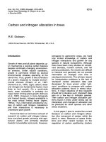
2.1 Diagram of MFCs technology principles in wastewater treatment
9
2.2 DET mechanisms to anode
11
2.3 Shortcut nitrification-denitrification process in MFCs
22
2.4 Mechanism of heterotrophic anodic denitrification process in MFCs
24
3.1 The main components of the coupled MFCs
32
3.2 The procedure for pretreatment of CEM
33
3.3 The procedure for pretreatment of electrode
33
3.4 Schematic diagram of start-up stage
35
3.5 Summary of operational stage
36
3.6 Schematic diagram of the first operational mode
37
3.7 The second mode operating schematic of the coupled MFC system
38
3.8 The third mode operating schematic of the coupled MFC system for shortcut
nitrification-denitrification
40
4.1 Cell votage progression (Rext = 500 Ω) during 30 days start-up in both MFC
reactors
44
4.2 (A) Polarization curve and power curve of N-MFC. (B) Cell votage vs. current
of N-MFC
45
4.3 (A) Polarization curve and power curve of D-MFC. (B) Cell votage vs. current
of D-MFC
46
4.4 Cell voltage progression of the coupled MFC in the first mode with different
COD influents (A – 1000 mg L-1, B – 1500 mg L-1, C – 2000 mg L-1)
48
4.5 Output pH of each chamber in the first mode operation with different COD
influents
54
4.6 (A) Polarization curve and power curve of N-MFC. (B) Cell votage vs. current
of N-MFC
55
4.7 (A) Polarization curve and power curve of D-MFC. (B) Cell votage vs. current
of D-MFC
56
Ref. code: 25656222300219VQS
(11)
4.8 Cell voltage of N-MFC and D-MFC during the second operational mode
(A, B, C – nitrogen input of 50, 75, 100 mg L-1, respectively)
58
4.9 Chemical analysis of the effluent from each chamber of the coupled MFC
system in the second operational mode (n.d: not detectable)
61
4.10 Output pH of chambers in the coupled MFC with different nitrogen influents 64
4.11 Cell voltage progression of the coupled MFC system during operation
(1, 2, 3, 4 correspond to the first to fourth operating conditions)
66
4.12 Cell voltage vs. current of N-MFC when conducting polarization test
(1, 2, 3, 4 correspond to the first to fourth operating conditions)
71
4.13 Chemical analysis of the effluent from each chamber of the coupled MFC
system in four operating conditions (n.d: not detectable)
73
4.14 The pH of each chamber’s output under various operating conditions.
78
4.15 SEM images of electrodes (O – before operation; A, B, C, D – anode of
N-MFC, cathode of N-MFC, anode of D-MFC, cathode of D-MFC after
operation, respectively)
82
Ref. code: 25656222300219VQS
(12)
LIST OF SYMBOLS/ABBREVIATIONS
Symbols/Abbreviations
Term
AEM
Anion Exchange Membrane
AOB
Ammonia-Oxidizing Bacteria
AO
Anoxic-Oxic
BNR
Biological Nitrogen Removal
CEM
Cation Exchange Membrane
DET
Direct Electron Transfer
DO
Dissolved Oxygen
ER
External Resistance
IR
Internal Resistance
MET
Mediated Electron Transfer
MFC
Microbial Fuel Cell
NOB
Nitrite-Oxidizing Bacteria
SND
Simultaneous Nitrification-Denitrification
TOC
Total Organic Carbon
UASB
Upflow Anaerobic Sludge Blanket
Ref. code: 25656222300219VQS
1
CHAPTER 1
INTRODUCTION
1.1 Problem statement
Organic matter contains carbon, hydrogen, oxygen, and other trace elements
and is the primary pollutant in wastewater. The release of wastewater with a significant
quantity of organic matter endanger the water ecosystem because the degradation of
these organic compounds utilizes dissolved oxygen (DO) in water, causing a lack of
DO for aquatic life (Nora’aini et al., 2005). Besides carbon, nitrogen is also a notable
parameter in wastewater. High nitrogen concentrations cause eutrophication in ponds,
lakes, canals, rivers, and coasts. As a result, the planktonic algae overgrowth depletes
the DO in water, clogs water intakes, blocks light to deeper waters, and destroys the
ecosystem (Howarth and Marino, 2006). An excessive amount of nitrate in groundwater
can cause methemoglobinemia, which interferes with the circulation of oxygen in the
blood (Feleke and Sakakibara, 2002). Besides, the water bodies where wastewater is
received may be the influent of the water treatment plant, supplying water for humans.
As a result, the cost of water treatment to meet standards for drinking or production.
Therefore, wastewater treatment is essential before discharging it into the environment.
Carbon and nitrogen criteria always received special attention from the designers of
wastewater treatment plants when choosing technology.
Most organic compounds in wastewater are easily degraded by microorganisms.
In most wastewaters, nitrogen is encountered mainly as ammonium and organic
nitrogen (Rittmann and McCarty, 2001). Organic nitrogen is converted to ammonium
through the ammonification process made by heterotrophic bacteria. Part of the
ammonium in wastewater is used as the N source to synthesize new biomass.
Nitrification and denitrification processes can eliminate the rest. The nitrification
process consists of successive nitrogen oxidation steps, which are nitritation and
nitratation. Nitritation is the process in which ammonia-oxidizing bacteria (AOB)
oxidize ammonium to nitrite, while nitratation involves nitrite-oxidizing bacteria (NOB)
converting nitrite to nitrate. The denitrification process includes consecutive nitrogen
oxides reduction steps, the desired final product of which is nitrogen gas, removed from
Ref. code: 25656222300219VQS
2
the wastewater. Denitrification bacteria use the biodegradable organic carbon as the
source of electrons in these processes. Many technologies can currently be selected for
wastewater treatment, most of which use biotechnology because of its sustainability
and low cost. Conventional technologies, like the anoxic-oxic (AO) system based on
the activated sludge processes are favored for its ability to remove organic substance
and nitrogen simultaneously. However, these treatment methods consume a significant
quantity of energy for aeration, which accounts for nearly half of the total operational
energy (Drewnowski et al., 2019). This energy is required to provide oxygen for the
oxidation of organic matter and results in the generation of substantial sludge that needs
to be properly managed. Anaerobic biological technology, such as upflow anaerobic
sludge blanket (UASB) reactors, offers advantages including not requiring air supply,
low solid yield, methane production as biofuel. However, anaerobic treatment has low
organic removal efficiency and is very limited in nitrogen removal, resulting in lowquality effluent and needs additional treatment for the remaining pollutant. Slow startup
and high-temperature requirements are also disadvantages of anaerobic treatment
(Chong et al., 2012). In addition, produced biogas needs to be pretreated (separation
and purification) before being used to generate electricity. In terms of cost-benefit
analysis, this is not feasible for small wastewater treatment plants (Gude, 2016). The
anammox microorganisms derive their energy from the reaction of ammonium and
nitrite to generate nitrogen gas. Therefore, anammox processes with the participation
of AOB and anammox bacteria have some outstanding benefits such as oxygen-saving
for nitrification, eliminating external carbon source requirement for denitrification, and
low sludge production (Cho et al., 2010). Nevertheless, its drawback is the complicated
operational control. The anammox biomass not only grows extremely slowly but is also
easily washed out during operation (Huynh et al., 2019).
In certain wastewater types where the C/N ratio is imbalanced due to carbon
source deficiency, achieving complete nitrogen removal is not possible (Smith and
Solley, 2002). Therefore, the addition of external carbon sources such as methanol,
ethanol, molasses becomes necessary to achieve the desired C/N ratio for heterotrophic
denitrification. This has resulted in concerns about increased treatment costs as well as
safety issues in chemical transport and storage. Even if the C/N ratio is theoretically
sufficient, conventional technology still needs very high internal recirculation from
Ref. code: 25656222300219VQS
3
aerobic to anoxic for high nitrogen removal efficiencies, resulting in increased pumping
cost. Also, the aerobic tank's circulating flow with a high DO concentration causes an
adverse environment for denitrification at the anoxic tank. Another limitation of the DO
presence in the anoxic tank is that aerobic digestion of readily biodegradable organic
carbon wastes the electron supplier for denitrification (Sander et al., 2017).
Lately, microbial fuel cells (MFCs) technology provides an encouraging
solution to treat wastewater sustainably, as it can directly generate electricity using
wastewater (Priya et al., 2022; Sun et al., 2016). Most MFC reactors consist of anode
and cathode electrodes placed separately in two chambers. An ion-exchange membrane
is employed to split up electrolyte solutions in two chambers. Microorganisms can be
used in MFC as biological catalysts, oxidizing organic substances in the electrolyte
solution and producing electrons flow from anode to cathode, while ions diffuse across
the membrane in the opposite direction to maintain a neutral charge. The ability of
MFCs to harness the energy stored in the chemical bonds of organic matter present in
wastewater and convert it into electrical power aligns with the new perspective of
considering wastewater as a valuable resource. In terms of wastewater treatment, MFCs
can remove carbon and nitrogen simultaneously through a series of redox reactions at
the two electrodes. Electrons produced at the anode through carbon oxidation reactions
flow via an electrical circuit to the cathode, where they are utilized in the reduction
reaction, combining with nitrate to form nitrogen gas. Thanks to the bacteria and
electrolytes separation in two chambers, the amount of organic carbon oxidized by
aerobic microorganisms is minimized, thus reducing the C/N ratio requirement
compared to conventional technologies (Virdis et al., 2011). The denitrification process
that occurs at the cathode of MFCs includes both bioelectrochemical denitrification
(autotrophic
denitrification)
and
conventional
denitrification
(heterotrophic
denitrification) (Zhang and He, 2012). In particular, autotrophic denitrification has
some benefits compared with the heterotrophic system such as lower biomass formation,
less organic matter required, no need further steps for removing the excess substrate
(Van Rijn et al., 2006). Besides, the employment of anaerobic microorganisms to
oxidize the carbon at the anode reduces sludge generation as well as aeration energy of
the whole MFCs system (since oxygen is only required for the nitrification process),
while electrical power generated has been shown to partially support the pumping
Ref. code: 25656222300219VQS
4
system (Zhang and He, 2012). Wang et al. (2013) reported that recovered energy from
MFCs helped to save 30–50% in operational costs.
Because of these apparent advantages, MFCs have attracted many researchers
with a significant quantity of publications in the field of treating wastewater (Santoro
et al., 2017). Most of the research aims to improve the power recovered from
wastewater and the efficiency of removing carbon and nitrogen. Some modified
configurations of MFCs have been applied, such as two-chambers MFC (Virdis et al.,
2008), single-chamber MFC with the exposed-air cathode (Hussain et al., 2016), singlechamber MFC with the rotating cathode (Zhang et al., 2013), membrane-less MFC (Zhu
et al., 2013), tubular dual-cathode MFC (Zhang and He, 2012), oxic/anoxic-cathode
MFC (Xie et al., 2011), stacked five-units MFC (Park et al., 2017). In parallel, many
types of ion-exchange membranes and electrode materials are also tested, and certain
performance improvements are achieved. Although the results showed a good carbon
removal efficiency above 80%, the nitrogen removal efficiency fluctuated significantly
and ranged from 36% to 97%, depending on experimental conditions. The parameters
affecting the nitrogen removal in MFC were investigated and evaluated such as carbon
sources (Feng et al., 2013), C/N ratio (Huang et al., 2013a), pH (Clauwaert et al., 2009),
DO (Virdis et al., 2010), and electrolyte conductivity (Puig et al., 2012). Because
successful nitrogen removal in wastewater involves nitrification and denitrification
processes, researchers found some methods to integrate these two processes into MFC
technology. Some studies conducted nitrification and denitrification separately by using
an independent nitrification reactor (Virdis et al., 2008), using a rotating cathode or
dual cathode (Xie et al., 2011; Zhang and He, 2012; Zhang et al., 2013). Some other
research performed simultaneously these two processes by controlling aeration in the
cathodic chamber (Virdis et al., 2010; Wu et al., 2017) or using the air cathode (Hussain
et al., 2016).
Although nitrite has been proven capable of replacing nitrate to become the
primary electron acceptor from the cathode (Puig et al., 2011; Virdis et al., 2008), the
shortcut nitrification/denitrification process in MFC has not been fully understood.
Theoretically, this process could decrease oxygen required for nitrification by 25% and
carbon needed for denitrification by 40% compared with nitrogen removal via nitrate.
In addition, the nitrite reduction rate can be up to 2 times faster than nitrate, while sludge
Ref. code: 25656222300219VQS
5
generation is also decreased by 40% in the nitritation/denitritation process (Beylier et
al., 2011). In MFCs, nitrite's electron utilization is better than that of nitrate, resulting
in higher coulombic efficiency on cathodic reaction (Virdis et al., 2008). At high
temperature (> 30oC), AOB biomass may dominate over NOB biomass, favoring nitrite
accumulation for denitritation process (Hellinga et al., 1998). Therefore, industrial
wastewater released with high temperature as dyeing wastewater may be suitable for
the shortcut nitrification/denitrification process without wastewater heating.
Most MFC reactors were designed with a separator between the two chambers
to prevent crossover processes that could have adverse effects, drastically reducing
MFC performance (Santoro et al., 2017). The fundamental requirement of the separator
is to be conductive for ions to balance the overall charge transfer during the operation
of the MFC. Therefore, ion exchange membranes are a good choice for separators, such
as cation exchange membranes (CEMs). However, they are pricey, accounting for the
significant investment costs of MFC systems. In addition, the poor selectivity of CEMs
and the overwhelming concentrations of other cations such as Na+, K+, and NH4+
compared to protons in wastewater resulted in low protons transfer efficiency
(Rozendal et al., 2006). This creates a pH imbalance between the two chambers, which
leads to a decrease in MFC performance (Nguyen and Babel, 2022). However, from
another perspective, this weakness can be exploited to an advantage by using ion
exchange membranes to isolate nitrogen from influent wastewater. This allows an MFC
reactor to be fully configurable to optimize energy recovery from organics while the
isolated ammonium oxidation contributes to pH balance. Recent research also explored
membrane penetration of nitrogen and took advantage of them to aid in nitrogen
removal in a dual-chamber MFC (Jin et al., 2022).
Despite the advantages of integrating biological nitrogen removal (BNR) into
MFC and the promising results in organic carbon removal, achieving high nitrogen
removal efficiency while optimizing energy recovery from organic matter remains a
challenge. A dual-cathode chamber MFC attained a total nitrogen removal of 99.9%,
but its power generation was low at 294.9 mW m-2 despite DO conditions of 3.5 (Li et
al., 2016). A single MFC reactor, operated with an external resistance (ER) of 10 Ω,
can attain a peak power density of 4.2 W m-3 and an overall nitrogen removal of less
than 80% (Wu et al., 2017). Theoretically, these two objectives are difficult to
Ref. code: 25656222300219VQS
6
accomplish concurrently in an MFC reactor. Firstly, high nitrogen removal occurs at
the lowest possible ER of an MFC (Li et al, 2014). However, to obtain maximum power
density, ER needs to be set close to internal resistance (IR) of the MFC system (Chen
et al., 2019; Li et al., 2016; Park et al., 2017). Basically, utilizing nitrate or nitrite as
electron acceptors at the cathode causes the IR to be high compared to utilizing oxygen
for the same purpose (Guo et al., 2020; Li et al., 2016; Zhang et al., 2020). As a result,
it is difficult to select an ER value that satisfies both goals. Secondly, O2/H2O has a
higher redox potential (+0.82 V) than that of NO3-/N2 (+0.75 V) and NO2-/N2 (+0.35 V)
(Nguyen and Babel, 2022). Therefore, oxygen reduction can produce a higher cell
voltage than denitrification at the cathode. However, the presence of oxygen at the
cathode has a negative impact on the denitrification process, decreasing the nitrogen
removal efficiency. Finally, conducting simultaneous nitrification-denitrification (SND)
in an MFC reactor requires complex control of operating parameters and does not
benefit in the power generation from organic material biodegradation (Virdis et al,
2010). A dual-cathode MFC (Li et al, 2016; Zou et al, 2018) or a coupled MFC system
(Chen et al, 2019; Xie et al, 2011) has been used to separate the nitrification and
denitrification processes. It has been reported that a stacked MFC with the effluent of
one unit being the influent of the next unit can help improve electricity generation by
decreasing IR within the system (Jadhav et al., 2021; Walter et al., 2016). Five stacked
MFC units successfully treated low-strength wastewater and reduced the hydraulic
retention time (HRT) to 2.5 h (Park et al, 2017).
To address these limitations, this study aimed to operate a coupled MFC to treat
synthesis wastewater. The chambers of a coupled MFC system can be sequencing-batch
operated with some specific goals established to design a proper configuration and
control the favorable conditions for each chamber (Nguyen and Babel, 2022). Setting
suitable levels of different parameters in each chamber is required to achieve the goal
of energy recovery from organic carbon and nitrogen removal. With this approach, in
this study, BNR was integrated into a coupled MFC with four chambers sequencingbatch operated to enhance nitrogen removal and energy recovery. To overcome the
current gap in achieving this dual objective, distinct ERs were built for the two MFC
reactors of a coupled MFC system. The first MFC (N-MFC) was responsible for power
generation from organic carbon and ammonium oxidation in the input wastewater. The
Ref. code: 25656222300219VQS
7
second MFC (D-MFC) facilitated nitrogen removal in presence of minimum carbon as
required for the denitrification process.
1.2 Research objectives
This study evaluates the removal efficiency of carbon and nitrogen
accompanied by power generation from synthetic wastewater. Different sequencingbatch operation modes are applied to four chambers of a coupled MFC for optimizing
recovery of electrical energy from organic matter in parallel with efficient nitrogen
treatment. Results of study will offer a deeper understanding of integrating the BNR
process into MFC technology. Batch-sequencing operation is expected to bring a
potential technical solution. Depending on operation mode, the following specific
objectives are proposed.
(1)
To investigate the effect of DO, and initial ammonium concentration for
ammonium oxidation and power generation from N-MFC.
(2)
To assess the ability of ammonium diffusion through CEM in N-MFC.
(3)
To investigate the effect of the COD/N ratio on nitrogen removal in D-MFC.
(4)
To evaluate the coulombic efficiency of the system.
(5)
To evaluate the ratio of autotrophic denitrification in cathodic chamber of DMFC.
1.3 Scope of research
To meet the aforementioned objectives, two dual-chamber MFC reactors were
constructed at a laboratory scale. All experiments were conducted in sequencing-batch
mode with synthesis wastewater. Influent synthesis wastewater COD concentration was
varied within 1000-2000 mg L-1, while ammonium nitrogen was between 50-100 mg
L-1. Bio-catalysts in the anode and the cathode were inoculated by anaerobic and
facultative microorganisms, respectively. DO in the cathode chamber of N-MFC was
controlled at three different values of 0.6 mg L-1, 1.2-1.24 mg L-1 and 4 mg L-1. The
temperature of the cathode chamber of N-MFC was maintained at room temperature
and 37oC. Observed parameters are pH, COD, NH4+-N, NO2--N, and NO3--N from the
output of each chamber and cell voltage generated from each MFC reactor.
Ref. code: 25656222300219VQS
8
CHAPTER 2
LITERATURE REVIEW
2.1 Principle of MFCs technology
An MFC is a bioelectrochemical system that its electrochemical reactions occur
by the interaction between microorganisms and electrodes (Mook et al., 2013).
Operation principle of MFCs relied on the electron donation and acceptance of pairs of
redox reactions, including the anaerobic oxidation of organic material by
microorganisms at the anode and the reduction of higher electrochemical potential
substances at the cathode. Electrical energy is recovered from the biodegradation of
organic matter by connecting the two electrodes with an electric wire to capture
electrons' flow. Table 2.1 shows the redox reactions in MFCs (Nguyen and Babel, 2022).
A typical dual-chamber MFCs with CEM used to treat wastewater is shown in Fig. 2.1.
Table 2.1 Redox reactions with theoretical potentials standard conditions in MFC
Reductant
Acetate
Glucose
Metanol
Glycerol
Carbon
Anodic reaction
CH3COO- + 4H2O 2HCO3- + 9H+ + 8eC6H12O6 + 12H2O 6HCO3- + 30H+ + 24eCH3OH + 2H2O HCO3- + 7H+ + 6eC3H5(OH)3 + 6H2O 3HCO3- + 17H+ + 14eC + 2H2O CO2 + 4H+ + 4e-
Oxidant
Cathodic reaction
Nitrate
Nitrite
Nitric oxide
Nitrous oxide
Proton
Oxygen
NO3- + 2H+ + 2e- NO2- + H2O
2NO3- + 12H+ + 10e- N2 + 6H2O
NO2- + 2H+ + e- NO- + H2O
NO- + H+ + e- 0.5N2O + 0.5H2O
0.5N2O + H+ + e- 0.5N2 + 0.5H2O
2H+ + 2e- H2
O2 + 4H+ + 4e- 2H2O
O2 + 2H+ + 2e- H2O2
Ean (V vs. SHE)
-0.279
-0.414
-0.453
-0.385
-0.207
Ecat (V vs.
SHE)
+0.433
+0.749
+0.350
+1.175
+1.355
0
+0.815
+0.280
Ref. code: 25656222300219VQS
9
Figure 2.1 Diagram of MFCs technology principles in wastewater treatment
The anodic oxidation reactions and the cathodic reduction reactions are referred
to as half-cell reactions. Its potentials can be calculated following Logan et al. (2006).
E
G
G 0 RT M red
ln
nF
nF nF M ox
E E0
M
M
RT
0.05916
log red E 0
log red
nF log e
n
M ox
M ox
(2.1)
(2.2)
where E (V) is the theoretical electrode potential in a certain condition, E0 (V) is the
standard potential (at 298 K, pH2 = 100 kPa, [H+] = 1 M), G is the Gibbs free energy
of formation, G0 is the standard Gibbs free energy of formation, R (J/mole/K) = 8.314
is the value of gas constant, T (K) is the thermodynamic temperature on the Kelvin
scale, F (Coulombs/mole) = 96500 is the Faraday constant, n is the number of electrons
exchanged in the reaction, Mred (mol/L) is the molar concentration of reductants, Mox
(mol/L) is the molar concentration of oxidants. For example, if the MFCs reactor is
setup following Figure 2.1, we have
E An
CH COO
0.05916
3
E
log
2
HCO H 9
8
3
(2.3)
P H O 6
0.05916
N2
2
log
2
12
10
NO3 H
(2.4)
0
An
ECat E
0
Cat
Ref. code: 25656222300219VQS
10
assume that the ideal condition are [NO3-] = [H2O] = [CH3COO-] = [HCO3-] = 1 M, PN2
= 1 atm, pH = 7 ([H+] = 10-7 M) and do not change with time. E0 can be calculated from
given G0 (Alberty, 2006), we have the same results as shown in table 2.1.
E An 0.187
0.05916
1
log
0.279 (V )
10 7 9
8
(2.5)
ECat 1.246
0.05916
1
log
0.749 (V )
107 12
10
(2.6)
The ideal electromotive force Eemf (V), also referred to as the ideal cell voltage, is
defined as the potential difference between the cathode and the anode.
Eemf = ECat – EAn = 0.749 - (-0.279) = 1.028 (V)
(2.7)
If the ohmic loss and overpotentials of two electrodes are taken into account, the actual
cell voltage is considerable lower than the ideal electromotive cell force (Logan et al.,
2006)
Ecell Eemf a c IR
(2.8)
Overvoltage
where a, |c| (V) are the overpotentials of the anode and cathode respectively, I (A)
is the produced current, and RΩ is the ohmic resistance of the MFC system. Besides,
the actual cell voltage also can be calculated as
Ecell = OCV – IRint
(2.9)
where OCV (V) is the open-circuit voltage measured immediately after the circuit
removes, I (A) is the produced current, Rint is the IR of the MFC system.
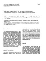
An indispensable factor in the operation of MFCs is the microbial capacity to
transfer electrons to the surface of the electrode. This type of microorganism is
commonly referred to as electrochemically active bacteria or exoelectrogen. Two
primary electron transfer mechanisms are direct electron transfer (DET) (Fig. 2.2) and
mediated electron transfer (MET) described by Sun et al. (2016). Besides transferring
electrons directly to the electrode via outer membrane c-type cytochrome, the flavin
bound to c-type cytochrome, Geobacter and Shewanella species can also form its
biological nanowire, allowing them to transport electrons to the anode surface in further
distances (Mook et al., 2013). These two species (e.g. Geobacter metallireducens,
Ref. code: 25656222300219VQS
11
Geobacter sulfurreducens, Shewanella oneidensis, Shewanella putrefaciens) were
frequently detected in many MFCs studies. MET is an indirect electron transfer
performed by mediators, additionally provided externally or generated by certain
microbes. The mediators act as shuttles; they receive electrons from the microbe and
transport them to the electrode's surface.
Figure 2.2 DET mechanisms to anode
2.2 Design of MFCs
To date, the design of MFCs has reached many advances in the wastewater
treatment study. Researchers focused on MFCs configuration, electrode, separator,
inoculum, and electrolyte solution to improve carbon and nitrogen removal efficiency,
increase power productivity, minimize costs, and enhance the MFCs system's stability.
2.2.1 Casing
The general feature of the materials used as the casing of the MFCs reactor in
lab-scale is non-conductive, such as glass, plastic, polycarbonate, plexiglass. The
shapes of chambers are also varied. The most common shapes used are cylindrical and
Ref. code: 25656222300219VQS