Study on camera based real time car speed monitor using yolov5 multiple object detection model
Bạn đang xem bản rút gọn của tài liệu. Xem và tải ngay bản đầy đủ của tài liệu tại đây (5.49 MB, 101 trang )
VIETNAM NATIONAL UNIVERSITY HO CHI MINH CITY
HO CHI MINH CITY UNIVERSITY OF TECHNOLOGY
NGUYEN NGOC TRUC
STUDY ON CAMERA-BASED REAL-TIME
CAR SPEED MORNITOR USING YOLOv5
MULTIPLE OBJECT DETECTION MODEL
Major: Vehicle Engineering
Major code: 8520116
MASTER’S THESIS
HO CHI MINH CITY, July 2023
THIS THESIS IS COMPLETED AT
HO CHI MINH CITY UNIVERSITY OF TECHNOLOGY – VNU-HCM
Supervisor: Trần Đăng Long, Ph.D
Examiner 1: Trần Hữu Nhân, Ph.D
Examiner 2: Nguyễn Văn Trạng, Ph.D
This master’s thesis is defended at HCM City University of Technology,
VNU- HCM City on July 15th, 2023
Master’s Thesis Committee:
1. Chairman: Lê Tất Hiển Assoc.Prof.Ph.D
2. Member: Võ Tấn Châu, Ph.D
3. Secretary: Hồng Đức Thông, Ph.D
4. Reviewer 1: Trần Hữu Nhân, Ph.D
5. Reviewer 2: Nguyễn Văn Trạng, Ph.D
Approval of the Chairman of Master’s Thesis Committee and Dean of Faculty
of Transportation Engineering after the thesis being corrected (If any).
CHAIRMAN OF THESIS COMMITTEE
i
HEAD OF FACULTY OF
TRANSPORTATION ENGINEERING
VIETNAM NATIONAL
UNIVERSITY HO CHI MINH CITY
HO CHI MINH CITY
UNIVERSITY OF
TECHNOLOGY
SOCIALIST REPUBLIC OF VIETNAM
Independence – Freedom - Happiness
THE TASK SHEET OF MASTER’S THESIS
Full name: Nguyễn Ngọc Trực
Studen code: 2170108
Date of Birth: 30/07/1996
Place of birth: Đăk Lăk
Major: Vehicle Engineering
Major code: 8520116
I. THESIS TOPIC: Study on camera-based real-time car speed monitor using
YOLOv5 multiple object detection model.
ĐỀ TÀI LUẬN VĂN : Nghiên cứu ứng dụng mơ hình YOLOv5 nhận diện đa
vật thể trong ảnh cho hệ thống giám sát tốc độ xe bằng camera theo thời gian
thực.
II. TASKS AND CONTENTS:
-
Develop a traffic sign recognition system, specifically for speed limit signs,
from images captured by cameras on the road.
Employ the Jetson Nano embedded computer as the central processing unit to
run the YOLOv5 model for detecting speed limit signs. Simultaneously,
compare the sign recognition results with the vehicle's current speed accessed
from the OBD-II system. Subsequently, the system provides a direct alert to
the driver on the screen if the speed limit is exceeded.
III. TASKS STARTING DATE: February 06th, 2023.
IV. TASKS ENDING DATE: June 12th 2023.
VIII. INSTRUCTOR: Trần Đăng Long, Ph.D.
Ho Chi Minh City, July 15th 2023.
INSTRUCTOR
(Full name & Signature)
HEAD OF DEPARTMENT
(Full name & Signature)
DEAN - FACULTY OF TRANSPORTATION ENGINEERING
(Full name & Signature)
ii
ACKNOWLEDGEMENT
I would like to express my heartfelt gratitude to my thesis advisor, Ph.D Tran
Dang Long, for his invaluable guidance, unwavering support, and continuous
encouragement throughout the entire duration of this thesis. His expertise, insightful
feedback, and constructive criticism have immensely contributed to the success of
this research endeavor.
I am also deeply grateful to Ho Nam Hoa, for his assistance and collaboration
in helping me establish the OBD-II CAN communication. His technical knowledge,
dedication, and willingness to share his expertise have been instrumental in
overcoming challenges and achieving significant milestones in this project.
Furthermore, I extend my sincere appreciation to my friend, Bui Huu Nghia,
for his valuable contribution in collecting the dataset. His commitment, attention to
detail, and assistance in data acquisition have greatly enriched the quality of this
research.
I would also like to acknowledge the support and encouragement received
from my family and friends throughout this academic journey.
Lastly, I am grateful to all the individuals who have directly or indirectly
contributed to the completion of this thesis. Their support, guidance, and
encouragement have been indispensable in shaping my research and personal growth.
Ho Chi Minh City, 15th July, 2023
Researcher,
Nguyen Ngoc Truc
iii
ABSTRACT
This study aims to two objectives. Firstly, the design of a real-time traffic sign
detection system for automobiles, with a specific focus on speed limit signs, using
the YOLOv5 model. Secondly, the study includes an assessment of the practical
implementation of the traffic sign detection system by integrating it with a speed
warning system that can be integrated into vehicles.
This study includes several key tasks. Firstly, extensive research was
conducted to identify real-time detection methods suitable for traffic signs.
Subsequently, a comprehensive dataset of speed limit traffic signs was prepared,
consists of 3200 images. The next step involved training a model for the detection of
these speed limit signs with the result of mAP 0.922 across 10 classes. The model
was then implemented on a Jetson Nano embedded computer. Parallelly, an ESP32
microcontroller was utilized to extract actual vehicle speed data from the OBD-II
system. Lastly, the speed limit traffic sign detection system and the actual vehicle
speed information were seamlessly integrated to develop a speed warning system.
The experimental results demonstrate the efficiency of the proposed traffic
sign detection system in this study. The YOLOv5 model achieves 4 frames per second
(FPS) on Jetson Nano computer in real-time detection speed. Moreover, by
integrating the speed limit sign detection system with real-time monitoring of the
actual vehicle speed, it enables timely warnings to the driver in the event of exceeding
the speed limit.
Additionally, the experimental results showed limitations of the speed limit
traffic sign detection system. One such limitation is its inability to detect the number
of lanes on the road, which affects its accuracy in providing the precise speed limit,
particularly in residential areas. Furthermore, there were instances where untrained
traffic signs were mistakenly detected as speed limit signs. To address these issues, it
is recommended to expand the training dataset to include a wider range of traffic
signs, not limited to speed limit signs alone.
In summary, the developed system exhibits significant potential for
applications in the automotive industry, particularly in the field of Advanced Driver
Assistance Systems (ADAS).
iv
TÓM TẮT LUẬN VĂN THẠC SĨ
Nghiên cứu này nhằm đạt được hai mục tiêu chính. Thứ nhất, thiết kế một hệ
thống nhận diện biển báo giao thông theo thời gian thực cho ô tô, tập trung đặc biệt
vào biển báo giới hạn tốc độ, bằng cách sử dụng mơ hình YOLOv5. Thứ hai, nghiên
cứu bao gồm việc đánh giá khả năng ứng dụng thực tế của hệ thống nhận diện biển
báo giao thơng bằng cách tích hợp với một hệ thống cảnh báo tốc độ có thể sử dụng
trên xe ô tô.
Nghiên cứu này bao gồm một số nhiệm vụ chính. Đầu tiên, nghiên cứu xác
định được các phương pháp nhận diện biển báo giao thông theo thời gian thực. Sau
đó, đã chuẩn bị tập dữ liệu về biển báo giới hạn tốc độ, bao gồm 3200 hình ảnh. Bước
tiếp theo, huấn luyện một mơ hình để nhận diện các biển hạn chế tốc độ này với kết
quả mAP là 0.922 trên 10 loại biển báo giao thơng. Sau đó, mơ hình đã được triển
khai trên máy tính nhúng Jetson Nano. Đồng thời, đã sử dụng vi điều khiển ESP32
để trích xuất dữ liệu tốc độ thực tế của xe từ hệ thống OBD-II. Cuối cùng, hệ thống
nhận diện biển hạn chế tốc độ và thông tin tốc độ xe thực tế đã được tích hợp để phát
triển thành một hệ thống cảnh báo tốc độ.
Kết quả thử nghiệm thể hiện tính ứng dụng của hệ thống nhận diện biển báo
giao thơng được trình bày trong nghiên cứu này. Mơ hình YOLOv5 đạt được 4 khung
hình/giây (FPS) trên máy tính Jetson Nano trong quá trình nhận diện với thời gian
thực. Hơn nữa, bằng cách tích hợp hệ thống nhận diện biển báo giới hạn tốc độ với
việc giám sát tốc độ thực tế của xe, hệ thống cho phép cảnh báo kịp thời cho người
lái trong trường hợp vượt quá giới hạn tốc độ.
Ngoài ra, kết quả thử nghiệm cũng cho thấy những hạn chế của hệ thống. Một
trong những hạn chế đó là khả năng khơng thể nhận diện số làn đường trên đường,
điều này ảnh hưởng đến độ chính xác của hệ thống trong việc xác định giới hạn tốc
độ chính xác, đặc biệt là trong khu vực dân cư. Hơn nữa, có những trường hợp biển
báo giao thông chưa được huấn luyện bị nhận diện nhầm là biển báo giới hạn tốc độ.
Để khắc phục các vấn đề này, tập dữ liệu huấn luyện cần được đa dạng hơn cho các
loại biển báo giao thông khác, không chỉ giới hạn ở biển báo giới hạn tốc độ.
Tóm lại, hệ thống được phát triển cho thấy tiềm năng đáng kể cho các ứng
dụng trong ngành công nghiệp ô tô, đặc biệt là trong lĩnh vực Advanced Driver
Assistance Systems (ADAS).
v
THE COMMITMENT OF THE THESIS’ AUTHOR
I am Nguyen Ngoc Truc, Master’s student of Department of Vehicle Engineering,
Faculty of Transportation, class 2021, at Ho Chi Minh City University of Technology.
I guarantee that the information below is accurate:
(i)
I conducted all of the work for this research study by myself.
(ii)
This thesis uses actual, reliable, and highly precise sources for its
references and citations.
(iii)
The information and findings of this study were produced
independently by me and honesty.
Ho Chi Minh City, 15th July, 2023
Researcher,
Nguyen Ngoc Truc
vi
Contents
1
2
Introduction
1
1.1
Background . . . . . . . . . . . . . . . . . . . . . . . . . . . . . . . .
2
1.2
Literature Review . . . . . . . . . . . . . . . . . . . . . . . . . . . . .
4
1.2.1
Speed Warning Systems . . . . . . . . . . . . . . . . . . . . .
4
1.2.2
Traffic Sign Detection . . . . . . . . . . . . . . . . . . . . . .
7
1.2.3
Object Detectors . . . . . . . . . . . . . . . . . . . . . . . . .
8
1.3
Research Objectives . . . . . . . . . . . . . . . . . . . . . . . . . . . .
9
1.4
Research Methodology . . . . . . . . . . . . . . . . . . . . . . . . . .
10
1.5
Research Contents . . . . . . . . . . . . . . . . . . . . . . . . . . . . .
10
1.6
Scope of Research . . . . . . . . . . . . . . . . . . . . . . . . . . . . .
12
1.7
Research Contributions . . . . . . . . . . . . . . . . . . . . . . . . . .
12
1.8
Research Outline . . . . . . . . . . . . . . . . . . . . . . . . . . . . .
12
Fundamentals
14
2.1
Convolutional Neural Networks . . . . . . . . . . . . . . . . . . . . .
15
2.1.1
Convolutional Layer . . . . . . . . . . . . . . . . . . . . . . .
15
2.1.2
Pooling Layer . . . . . . . . . . . . . . . . . . . . . . . . . . .
17
2.1.3
Fully Connected Layer . . . . . . . . . . . . . . . . . . . . . .
18
2.1.4
Activation Function . . . . . . . . . . . . . . . . . . . . . . .
19
YOLOv5 . . . . . . . . . . . . . . . . . . . . . . . . . . . . . . . . . .
21
2.2.1
21
2.2
Introduce to YOLO . . . . . . . . . . . . . . . . . . . . . . . .
vii
CONTENTS
2.2.2
2.3
2.4
2.5
3
22
Evaluation Metrics . . . . . . . . . . . . . . . . . . . . . . . . . . . .
26
2.3.1
Confusion Matrix . . . . . . . . . . . . . . . . . . . . . . . . .
26
2.3.2
Intersection over Union . . . . . . . . . . . . . . . . . . . . .
28
2.3.3
Precision and Recall . . . . . . . . . . . . . . . . . . . . . . .
29
2.3.4
Mean Average Precision . . . . . . . . . . . . . . . . . . . . .
30
2.3.5
F1 Score . . . . . . . . . . . . . . . . . . . . . . . . . . . . . .
30
Toolchain . . . . . . . . . . . . . . . . . . . . . . . . . . . . . . . . . .
30
2.4.1
Roboflow . . . . . . . . . . . . . . . . . . . . . . . . . . . . .
31
2.4.2
Google Colaboratory . . . . . . . . . . . . . . . . . . . . . . .
31
Conclusion . . . . . . . . . . . . . . . . . . . . . . . . . . . . . . . . .
32
Design A Speed Limit Signs Detection Model
33
3.1
Prepare Dataset . . . . . . . . . . . . . . . . . . . . . . . . . . . . . .
34
3.1.1
Dataset Requirement . . . . . . . . . . . . . . . . . . . . . . .
35
3.1.2
Dataset Classes . . . . . . . . . . . . . . . . . . . . . . . . . .
35
3.1.3
Dataset Collection . . . . . . . . . . . . . . . . . . . . . . . .
37
3.1.4
Data Annotation . . . . . . . . . . . . . . . . . . . . . . . . .
38
3.1.5
Data Augmentation . . . . . . . . . . . . . . . . . . . . . . . .
38
3.1.6
Dataset Structure . . . . . . . . . . . . . . . . . . . . . . . . .
40
Training Model . . . . . . . . . . . . . . . . . . . . . . . . . . . . . .
41
3.2.1
Install dependencies . . . . . . . . . . . . . . . . . . . . . . .
41
3.2.2
Download Dataset . . . . . . . . . . . . . . . . . . . . . . . .
41
3.2.3
Training Model Parameters . . . . . . . . . . . . . . . . . . .
42
3.2.4
Training Results . . . . . . . . . . . . . . . . . . . . . . . . .
44
3.2
4
YOLOv5 Architecture . . . . . . . . . . . . . . . . . . . . . .
Experimental Evaluations
48
4.1
Experimental Preparation . . . . . . . . . . . . . . . . . . . . . . . . .
49
4.1.1
Hardware Circuit Diagram . . . . . . . . . . . . . . . . . . . .
49
4.1.2
Software Algorithm Flowchart . . . . . . . . . . . . . . . . .
50
viii
CONTENTS
4.2
4.3
4.4
5
Speed Limit Caching Algorithm . . . . . . . . . . . . . . . . .
51
4.1.4
Finite State Machine Based Speed Warning Algorithm . . . .
53
Experimental Apparatus . . . . . . . . . . . . . . . . . . . . . . . . .
55
4.2.1
Jetson Nano . . . . . . . . . . . . . . . . . . . . . . . . . . . .
55
4.2.2
Camera Raspberry Pi V2 . . . . . . . . . . . . . . . . . . . . .
57
4.2.3
ESP32 . . . . . . . . . . . . . . . . . . . . . . . . . . . . . . .
59
4.2.4
CAN Transceiver . . . . . . . . . . . . . . . . . . . . . . . . .
60
4.2.5
DC-DC Converter . . . . . . . . . . . . . . . . . . . . . . . .
61
4.2.6
OBD-II Adapter . . . . . . . . . . . . . . . . . . . . . . . . .
61
Deploy on Jetson Nano . . . . . . . . . . . . . . . . . . . . . . . . . .
62
4.3.1
Build Model Engine . . . . . . . . . . . . . . . . . . . . . . .
62
4.3.2
Run Model Engine . . . . . . . . . . . . . . . . . . . . . . . .
63
Experiment Conditions . . . . . . . . . . . . . . . . . . . . . . . . . .
64
Results and Discussions
66
5.1
System Setup . . . . . . . . . . . . . . . . . . . . . . . . . . . . . . .
67
5.2
Speed Limit Detection . . . . . . . . . . . . . . . . . . . . . . . . . .
69
5.2.1
Results . . . . . . . . . . . . . . . . . . . . . . . . . . . . . . .
69
5.2.2
Error Cases . . . . . . . . . . . . . . . . . . . . . . . . . . . .
72
Speed Warning Applications . . . . . . . . . . . . . . . . . . . . . . .
75
5.3
6
4.1.3
Conclusions and Future Works
78
References
80
Appendix
84
ix
List of Figures
1.1
Types of ADAS . . . . . . . . . . . . . . . . . . . . . . . . . . . . . .
2
1.2
GSpeed, based on GPS and developed by iCar . . . . . . . . . . . . .
5
1.3
Concept of Smart Road Signs communicate to vehicles . . . . . . . .
6
1.4
The comparison of YOLOv3 on performance . . . . . . . . . . . . . .
9
1.5
Research Contents and Workflows . . . . . . . . . . . . . . . . . . . .
10
2.1
An example of CNN architecture to classify handwritten digits . . . .
15
2.2
The Convolution Operation . . . . . . . . . . . . . . . . . . . . . . . .
16
2.3
An example of convolution with stride equal to 2 . . . . . . . . . . . .
16
2.4
An example of padding in convolutional . . . . . . . . . . . . . . . . .
17
2.5
An example of max pooling and average pooling . . . . . . . . . . . .
17
2.6
An example of the fully connected layer’s input multiplied by the
weights matrix to receive the output vector . . . . . . . . . . . . . . .
18
2.7
Plot of sigmoid activation function . . . . . . . . . . . . . . . . . . . .
19
2.8
Plot of tanh activation function . . . . . . . . . . . . . . . . . . . . . .
20
2.9
Plot of ReLU activation function . . . . . . . . . . . . . . . . . . . . .
20
2.10 How YOLO works . . . . . . . . . . . . . . . . . . . . . . . . . . . .
21
2.11 Darknet-53 Architecture . . . . . . . . . . . . . . . . . . . . . . . . .
23
2.12 (a) DenseNet and (b) Cross Stage Partial DenseNet . . . . . . . . . .
24
2.13 YOLOv5 Network Architecture . . . . . . . . . . . . . . . . . . . . .
25
2.14 Confusion Matrix Definition . . . . . . . . . . . . . . . . . . . . . . .
27
2.15 Computing the Intersection over Union . . . . . . . . . . . . . . . . .
28
x
LIST OF FIGURES
2.16 Define TP, FP base on IoU . . . . . . . . . . . . . . . . . . . . . . . .
29
2.17 The computer vision workflow on Roboflow . . . . . . . . . . . . . .
31
3.1
Dataset Preparation Workflows . . . . . . . . . . . . . . . . . . . . . .
34
3.2
Recorded Traffic Signs at Day and Night . . . . . . . . . . . . . . . .
38
3.3
Data annotating on roboflow . . . . . . . . . . . . . . . . . . . . . . .
39
3.4
Image before and after augmentation . . . . . . . . . . . . . . . . . .
39
3.5
Dataset Health Check before Augment . . . . . . . . . . . . . . . . .
40
3.6
Export Dataset with Download Code . . . . . . . . . . . . . . . . . .
42
3.7
The YOLOv5s Model Training Architecture . . . . . . . . . . . . . .
43
3.8
Training Results over 100 Epochs . . . . . . . . . . . . . . . . . . . .
44
3.9
Confusion Matrix . . . . . . . . . . . . . . . . . . . . . . . . . . . . .
45
3.10 Precision and Recall Curve . . . . . . . . . . . . . . . . . . . . . . . .
46
3.11 F1-Confidence Curve . . . . . . . . . . . . . . . . . . . . . . . . . . .
47
4.1
Concept of Experimental System . . . . . . . . . . . . . . . . . . . . .
48
4.2
Hardware Circuit Diagram . . . . . . . . . . . . . . . . . . . . . . . .
49
4.3
Software Algorithm Flowchart . . . . . . . . . . . . . . . . . . . . . .
50
4.4
Speed Limit Caching Algorithm . . . . . . . . . . . . . . . . . . . . .
52
4.5
FSM based speed warning algorithm . . . . . . . . . . . . . . . . . .
53
4.6
Jetson Nano Developer Kit B01 . . . . . . . . . . . . . . . . . . . . .
55
4.7
Camera Raspberry Pi V2 . . . . . . . . . . . . . . . . . . . . . . . . .
58
4.8
Microcontroller ESP32 . . . . . . . . . . . . . . . . . . . . . . . . . .
59
4.9
Module CAN Transceiver SN65HVD230 . . . . . . . . . . . . . . . .
60
4.10 DC-DC Buck Converter . . . . . . . . . . . . . . . . . . . . . . . . . .
61
4.11 OBD-II Male Adapter . . . . . . . . . . . . . . . . . . . . . . . . . . .
62
5.1
The system setup for experiment . . . . . . . . . . . . . . . . . . . . .
67
5.2
The system implemented on vehicle . . . . . . . . . . . . . . . . . . .
67
5.3
The system was tested on vehicle . . . . . . . . . . . . . . . . . . . .
68
5.4
Speed detection system being tested in afternoon environments . . . .
69
xi
LIST OF FIGURES
5.5
Speed detection system being tested in nighttime environments . . . .
70
5.6
Speed detection system being tested in various environments . . . . .
70
5.7
Speed detection system being tested in various environments . . . . .
71
5.8
The width limit signs mistaken by speed limit 50 km/h . . . . . . . .
72
5.9
Speed limit 80 km/h mistaken by speed limit 60 km/h in few frames .
73
5.10 Warning in case speed exceeds from 1-5 km/h . . . . . . . . . . . . .
75
5.11 Warning in case speed exceeds more than 5km/h . . . . . . . . . . . .
76
5.12 Warning in case speed falls below minimum from 1-5 km/h . . . . . .
76
5.13 Warning in case speed falls below minimum over 5 km/h . . . . . . .
77
xii
List of Tables
2.1
An example to calculate dimension of output activation map . . . . .
24
3.1
Traffic sign classes . . . . . . . . . . . . . . . . . . . . . . . . . . . .
36
4.1
Jetson Nano GPIO . . . . . . . . . . . . . . . . . . . . . . . . . . . . .
56
4.2
Technical specifications of Jetson Nano Developer Kit B01 . . . . . .
57
4.3
Technical specifications of Raspberry Pi Camera Module V2 . . . . .
58
4.4
ESP32 GPIO . . . . . . . . . . . . . . . . . . . . . . . . . . . . . . . .
59
4.5
Experiment Conditions . . . . . . . . . . . . . . . . . . . . . . . . . .
64
xiii
List of Abbreviations
ADAS Advanced Driver Assistance Systems
ACC
Adaptive Cruise Control
LDW
Lane Departure Warning
GPS
Global Positioning System
AI
Artificial Intelligence
CV
Computer Vision
CNN
Convolutional Neural Networks
YOLO You Only Look Once
OBD-II On-Board Diagnostics II
SWS
Speed Warning Systems
ROI
Regions of Interest
mAP
Mean Average Precision
FPS
Frames Per Second
R-CNN Region-Based Convolutional Neural Network
xiv
SSD
Single Shot MultiBox Detector
RPN
Region Proposal Network
tanh
hyperbolic tangent
ReLU
Rectified Linear Unit
SPP
Spatial Pyramid Pooling
TP
True Positive
TN
True Negative
FP
False Positive
FN
False Negative
IoU
Intersection over Union
AP
Average Precision
UART Universal Asynchronous Receiver-Transmitter
CSI
Camera Serial Interface
ECU
Electronic Control Unit
CAN
Controller Area Network
FSM
Finite State Machine
xv
Chapter 1
Introduction
This introduction chapter of the study consists of 8 sections. It begins with
a background explanation, highlighting the motivation behind selecting traffic sign
detection as the topic of study. The chapter then delves into an overview of Advanced
Driver Assistance Systems (ADAS) and emphasizes the importance of speed warning
systems within this context. It explains that the development of a speed warning
system necessitates a reliable model for detecting speed limit signs. The objectives of
the thesis are subsequently presented, outlining the specific goals to be achieved. The
research methodology and the contributions of the study are discussed, along with
the defined scopes of investigation. Finally, the chapter provides an outline of each
subsequent chapter, giving readers a preview of the topics covered in the thesis.
1
CHAPTER 1. INTRODUCTION
1.1
Background
Figure 1.1: Types of ADAS [1]
In recent years, Advanced Driver Assistance Systems (ADAS) have emerged as a
promising approach to enhance driving safety and reduce the number of accidents on
the road. ADAS utilize various technologies, such as sensors, cameras, and communication systems, to provide drivers with advanced warning and assistance in critical
driving situations.
One of the most common ADAS features is Adaptive Cruise Control (ACC),
which helps drivers maintain a safe distance from the vehicle in front by automatically adjusting the speed of the vehicle. Another important ADAS feature is Lane
Departure Warning (LDW), which alerts drivers when they are drifting out of their
lane. In addition, ADAS can also assist drivers in parking, with features such as parking sensors and automatic parking systems. Blind spot detection systems can also
provide drivers with visual or auditory warnings when there is a vehicle or obstacle
in their blind spot.
Speed Warning Systems (SWS) are also an important feature of ADAS, as speeding is a common cause of accidents. These systems can be implemented using various
technologies, such as Global Positioning System (GPS), camera-based object detection, and communication with roadside infrastructure. Some studies have shown that
2
CHAPTER 1. INTRODUCTION
speed limit warning systems can be effective in reducing speeding behavior and improving road safety [2].
Recent advancements in Artificial Intelligence (AI) and Computer Vision (CV)
have led to significant improvements in the accuracy and reliability of ADAS. Deep
learning based approaches, such as Convolutional Neural Networks (CNN), have
shown promising results in object detection and recognition tasks, which are important for ADAS.
Camera-based object detection has emerged as a promising technology for speed
limit warning systems. The You Only Look Once (YOLO) object detection model is a
state-of-the-art algorithm that has shown to be effective in detecting and tracking objects in real-time [3]. By using model YOLO to detect and track speed limit signs on
the road, a speed limit warning system can provide accurate and reliable information
to the driver about the current speed limit.
In addition to object detection, another key component of a speed limit warning
system is the ability to determine the vehicle’s current speed. The On-Board Diagnostics II (OBD-II) system is a standard feature in modern vehicles that provides
real-time information about the vehicle’s performance. By getting an data information
from OBD-II system into the speed limit warning system, the system can accurately
compare the vehicle speed with the detected speed limit signs and warn the driver if
they are exceeding the limit. Several studies have evaluated the effectiveness of speed
warning systems in real-world driving environments. These studies have shown that
speed warning systems can effectively reduce speeding behavior and improve driver
safety.
3
CHAPTER 1. INTRODUCTION
1.2
Literature Review
1.2.1
Speed Warning Systems
Speeding is a major cause of road accidents and poses significant risks to both
drivers and pedestrians. To address this issue, researchers and engineers have developed various speed warning systems for automobiles. These systems aim to alert
drivers when they exceed the speed limit, thereby promoting safer driving behavior.
In this literature review, we explore three commonly used methods for implementing
SWS: GPS-based systems, systems that communicate with roadside infrastructure,
and camera-based systems.
The SWS comprises two primary components. Firstly, it detects the speed limit
corresponding to specific road infrastructure. Secondly, it continuously monitors the
actual speed of the vehicle. By comparing the detected speed limit with the actual
vehicle speed, the system determines whether the driver is exceeding the speed limit.
If a violation is detected, the system generates appropriate speed warning messages
to alert the driver.
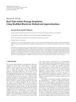
GPS-based SWS rely on GPS technology to determine the vehicle’s current location and calculate the corresponding speed limit. These systems typically use data
from GPS satellites to determine the vehicle’s location and speed, and cross-reference
this information with a digital map to determine the speed limit for that particular
stretch of road [4]. Recent studies have evaluated the effectiveness of SWS in improving driver behavior and reducing the number of accidents on the road. A study
conducted by Song Wang et al. [5] found that SWS were effective in reducing speeding behavior among drivers, and were particularly effective in areas with high accident rates. Furthermore, there are several popular SWS available in different countries, such as the speed limit warning feature in Google Maps [6], which is currently
available in over 40 countries excluding Vietnam. In the Vietnam market, there are
also speed warning systems like Vietmap [7], which utilize GPS and are directly in-
4
CHAPTER 1. INTRODUCTION
tegrated into their dash cameras. Another recently introduced software is GSpeed
by iCar [8], which was launched in June 2023 and can be integrated into the car’s
monitor. The utilization of GPS-based methods is widespread, but it necessitates a
substantial database. However, this approach has certain drawbacks, such as the lack
of real-time updates. In some instances, the speed limit may have changed, but the
system still relies on outdated information from its database. Additionally, when two
parallel routes exist, the system may struggle to accurately detect the correct road
being traveled on.
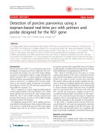
Figure 1.2: GSpeed, based on GPS and developed by iCar [8]
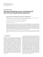
Another approach to SWS involves communication between the vehicle and
roadside infrastructure. These systems rely on the exchange of information between
the vehicle and infrastructure, such as traffic signs or intelligent transportation systems. By receiving speed limit data from the infrastructure such as smart road signs,
the system can promptly warn the driver if they are driving above the prescribed limit.
In 2016, Sharpe et al. [9] has implemented the wireless communications between
road signs and vehicles in order to determine the speed limit and issue warning messages if the driver exceeds the limit. The system involved multiple microcontrollers
that communicated with each other. One microcontroller was integrated into the traffic signs, while another was installed in the vehicle, allowing data to be exchanged
between them. This approach enabled accurate monitoring of the speed limit for the
vehicle. However, it should be noted that this method requires extensive investigation
5
CHAPTER 1. INTRODUCTION
and implementation of infrastructure on the road, which may not be feasible in the
current traffic conditions in Vietnam.
Figure 1.3: Concept of Smart Road Signs communicate to vehicles [9]
Camera-based SWS utilize computer vision techniques to detect and recognize
speed limit signs. In a study conducted by Chang et al. in 2015 [10], they developed a speed warning system for automobiles using computer vision techniques on a
mobile device. Their approach involved extracting red color pixels to define Regions
of Interest (ROI) and utilizing pre-defined template numbers for pattern matching.
However, this method had limitations. One drawback was that traffic signs can vary
in their fonts, requiring a diverse range of template numbers for accurate detection.
Additionally, environmental conditions such as rain or nighttime can cause blurriness
in the traffic signs, posing further challenges for detection.
Overall, SWS play a crucial role in promoting safe driving practices and reducing the occurrence of speeding-related accidents. This literature review examined
three popular methods for implementing speed warning systems: camera-based systems, GPS-based systems, and systems that communicate with roadside infrastructure. Each method offers unique advantages and has been the subject of extensive research. Camera-based systems leverage computer vision techniques to accurately detect speed limit signs, while GPS-based systems utilize GPS technology to determine
the vehicle’s position and calculate the corresponding speed limit. Communication6
CHAPTER 1. INTRODUCTION
based systems enable real-time information exchange between the vehicle and roadside infrastructure. Further research and advancements in these areas can contribute
to the development of more robust and effective SWS, ultimately enhancing road
safety and reducing the risks associated with speeding.
1.2.2
Traffic Sign Detection
Since 2010s, there has been a growing trend in utilizing camera-based object
detection systems for the purpose of traffic sign detection. This approach involves
the application of deep learning algorithms, particularly CNN, which have shown remarkable capabilities in accurately detecting and recognizing various types of traffic
signs [11, 12]. These systems can be trained to recognize a variety of traffic signs
including speed limit signs, and are able to work in a variety of lighting and weather
conditions. In the year 2022, a comparative experiment was conducted on the German
Traffic Sign Recognition benchmark dataset [13] with 43 classes, specifically comparing the performance of two popular object detection algorithms: Faster Region-Based
Convolutional Neural Network (R-CNN) [14] and YOLOv4 [15]. The results of this
experiment revealed that Faster R-CNN achieved a Mean Average Precision (mAP)
of 43.26% while operating at a speed of 6 Frames Per Second (FPS). On the other
hand, YOLOv4 exhibited superior performance with an mAP of 59.88% at a significantly higher detection speed of 35 FPS. These findings highlight the suitability of
YOLOv4 for real-time traffic sign detection, offering a combination of higher precision and faster detection speeds.
In summary, the use of deep learning for traffic sign detection has extensive applications and contributions. However, there is currently a gap in the implementation
of this technology for speed warning systems. Therefore, this study aims to fill this
gap by evaluating the application of deep learning algorithms in traffic sign detection
for speed warning purposes.
7
CHAPTER 1. INTRODUCTION
1.2.3
Object Detectors
Object detection is a fundamental problem in computer vision, with many applications such as autonomous driving and intelligent transportation systems. The two
main categories of object detection methods are one-stage and two-stage detectors.
One-stage detectors such as YOLO [3] and Single Shot MultiBox Detector (SSD) [16]
can detect objects in a single pass, while two-stage detectors such as Faster R-CNN
[14] and Mask R-CNN [17] first propose object regions before detecting the object
within those regions.
Faster R-CNN is a two-stage object detection method that first proposes object
regions and then classifies objects within those regions. It uses a Region Proposal
Network (RPN) to propose regions that might contain objects and then uses a second
network to classify objects within those regions. Faster R-CNN has high accuracy but
is slower than one-stage detectors such as YOLO and SSD [18].
Mask R-CNN extends Faster R-CNN by adding a branch to predict object masks
in addition to object classes and bounding boxes. It achieves state-of-the-art accuracy
in object detection and instance segmentation tasks, but it is computationally expensive and has a slow detection speed.
YOLO is a popular one-stage object detection method that uses a single neural
network to predict bounding boxes and class probabilities. It divides the input image
into a grid of cells and predicts the class probabilities and bounding boxes for each
cell. YOLO has a fast detection speed and can achieve real-time performance on
low-power devices [19].
SSD is another one-stage object detection method that predicts object classes
and bounding boxes from feature maps of different resolutions. It uses convolutional
filters of different sizes to detect objects at different scales. SSD is faster than Faster
R-CNN, but its accuracy is slightly lower, especially for small objects [18].
8
CHAPTER 1. INTRODUCTION
Figure 1.4: The comparison of YOLOv3 on performance [20]
Figure 1.4 illustrates the performance comparison between YOLOv3 and another
methods. It can be observed that YOLOv3 outperforms in terms of detection speed,
indicating its suitability for real-time object detection applications.
In summary, one-stage detectors such as YOLO and SSD are faster but have
lower accuracy compared to two-stage detectors such as Faster R-CNN and Mask
R-CNN. The choice of which method to use depends on the specific application
requirements such as speed and accuracy.
1.3
Research Objectives
This study has two objectives. The primary objective is to develop a real-time
traffic sign detection system, focusing specifically on the detection of speed limit
signs, utilizing the YOLOv5 model. The aim is to design and implement an efficient
and accurate algorithm that can detect and recognize speed limit signs in real-time
scenarios.
9