Swimming gait control of elongated undulating fins based on the central pattern generators
Bạn đang xem bản rút gọn của tài liệu. Xem và tải ngay bản đầy đủ của tài liệu tại đây (16.8 MB, 201 trang )
VIET NAM NATIONAL UNIVERSITY HO CHI MINH CITY
UNIVERSITY OF TECHNOLOGY
NGUYEN VAN DONG
SWIMMING GAIT CONTROL OF ELONGATED UNDULATING
FINS BASED ON THE CENTRAL PATTERN GENERATOR
DOCTOR OF SCIENCE DISSERTATION
HO CHI MINH CITY - 2023
VIET NAM NATIONAL UNIVERSITY HO CHI MINH CITY
UNIVERSITY OF TECHNOLOGY
NGUYEN VAN DONG
SWIMMING GAIT CONTROL OF ELONGATED UNDULATING
FINS BASED ON THE CENTRAL PATTERN GENERATOR
Major: Mechanical Engineering
Major code: 62520103
Independent reviewer 1:
Independent reviewer 2:
Assoc. Prof. Ngo Quang Hieu, PhD
Assoc. Prof. Nguyen Hung, PhD
Reviewer 1: Assoc. Prof. Truong Nguyen Luan Vu, PhD
Reviewer 2: Assoc. Prof. Nguyen Truong Thinh, PhD
Reviewer 3: Assoc. Prof. Nguyen Tan Luy, PhD
SCIENCE ADVISOR:
Assoc. Prof. Nguyen Tan Tien, PhD
COMMITMENT
I pledge that this is my work of myself. This dissertation's research results and conclusions are
honest and not copied from any sources or under any form. The references to the documentary
sources had been cited as prescribed.
Dissertation author
Signature
Nguyen Van Dong
iii
ABSTRACT
One of the inevitable consequences of modern warfare is the presence of explosive remnants
scattered throughout various areas, causing long-term adverse effects on the quality of life for
individuals. In the coastal regions of Vietnam, fishermen constantly face the potential risk posed
by undetonated mines still embedded in the seabed, often covered by layers of moss and mud.
Consequently, employing human clones to undertake detection and disposal tasks not only
demands substantial labor but also entails significant risks. Recognizing this limitation, several
units within the Vietnamese Navy have turned to underwater robots for conducting mine
clearance surveys. However, a new challenge arises from the specific characteristics of the mine
environment, which typically features mossy surroundings and accumulations of oceanic
debris. As a consequence, propeller-based robots encounter obstruction and inefficiency,
necessitating the exploration of solutions to address these pressing issues. The objective of this
thesis is to address the aforementioned pressing issue by investigating the optimal configuration
of parameters for the propulsion system of an underwater robot, utilizing the swimming
mechanism of the Gymnotiform fish class. This involves analyzing, selecting, and constructing
the motor controller structure for the underwater robot, inspired by the design of the South
American black knifefish and employing the central pattern generator (CPG) motor mechanism.
To achieve this, advanced optimization algorithms are employed to determine the specific
parameters of the CPG motor controller. Through the utilization of reinforcement learning
algorithms, the coefficient K, which governs the transition speed of the swimming pattern, is
determined. Additionally, stroke adjustments are made to minimize the time required for
swimming shape transformation while ensuring minimal output error compared to the desired
stroke. Furthermore, maintaining a consistent swimming frequency (The time required to
complete one cycle of coordination between the fins to generate a propulsion waveform),
avoiding fluctuations in underwater sound frequency to prevent the detonation of non-contact
fuse torpedoes (sonar turbulence), while still ensuring maximum thrust to rapidly navigate the
robot out of hazardous areas regardless of energy consumption, is crucial. To achieve this, the
thesis proposes the application of the swarm optimization algorithm to determine the set of
amplitude parameters A1, A2 ..., and A16, optimizing thrust output at a fixed frequency.
Following 4251 thrust simulations, a maximum thrust of 3.60N was obtained from the module.
The findings of this thesis have practical implications in optimizing the sets of CPG parameters
for longitudinal propulsion modules, tailored to specific frequency levels. These modules
enable flexible switching of swimming postures and facilitate optimal thrust generation based
iv
on mechanical characteristics. The proposed modules replicate the swimming mechanism of
the median and paired fins (MPF), laying the foundation for the development of higher-level
control algorithms for fish robots utilizing this modular propulsion system.
v
TÓM TẮT LUẬN ÁN
Một trong những hệ quả tất yếu của chiến tranh hiện đại là tàn tích vật liệu nổ cịn sót lại, gây
ảnh hưởng lâu dài đến sự an toàn của người dân. Đối với ngư dân vùng ven biển Việt Nam, họ
phải đối mặt với những nguy cơ tiềm ẩn từ thủy lơi cịn nằm dưới đáy biển, phủ đầy rong rêu
và bùn lầy. Việc sử dụng người nhái để thực hiện cơng việc tìm kiếm và phá hủy khơng chỉ tốn
nhân lực mà cịn mang đến nhiều rủi ro đến tính mạng của những người lính đặc công này. Gần
đây, một số đơn vị công binh Hải Quân Nhân Dân Việt Nam đã nhận thấy nhược điểm trên và
đã áp dụng robot dưới nước để thực hiện nhiệm vụ khảo sát và phá huỷ thủy lôi. Tuy nhiên,
một vấn đề mới đã xuất hiện do đặc điểm của mơi trường nơi thủy lơi cịn sót lại, thường có
nhiều rong rêu và rác thải đại dương. Các robot sử dụng chân vịt thường bị mắc kẹt và hoạt
động khơng hiệu quả, vì vậy cần có một giải pháp để giải quyết vấn đề này. Luận án này đóng
góp vào việc giải quyết vấn đề cấp bách trên bằng cách nghiên cứu tối ưu hóa một số thơng số
của hệ thống tạo lực đẩy cho robot dưới nước, theo cơ chế bơi của lớp cá Gymnotiform.
Bằng cách phân tích và lựa chọn cấu trúc bộ điều khiển vận động cho hệ thống tạo lực đẩy của
robot dưới nước, được lấy cảm hứng từ cấu trúc của cá dao đen ở Nam Mỹ và sử dụng cơ chế
vận động bộ thần kinh trung tâm (CPG), luận án này áp dụng các thuật toán tối ưu hiện đại để
lựa chọn các thông số của bộ điều khiển vận động CPG.
Cụ thể, thông qua sử dụng giải thuật học tăng cường, luận án lựa chọn các hệ số K đặc trưng
cho tốc độ chuyển đổi dáng bơi. Mục tiêu là đảm bảo thời gian chuyển đổi dáng bơi là thấp
nhất, đồng thời đáp ứng sai số đầu ra so với dáng bơi mong muốn là tối thiểu.
Ngoài ra, để đảm bảo tần số bơi nhất quán và tránh tạo ra biến động trong tần số âm thanh dưới
nước, nhằm tránh kích nổ hoặc gây nhiễu động sonar không mong muốn từ ngịi nổ khơng tiếp
xúc của thủy lơi, luận án đề xuất áp dụng giải thuật tối ưu bầy đàn. Giải thuật này được sử dụng
để tìm ra bộ thơng số biên độ A1, A2, ..., A16 cho lực đẩy tối đa tại cùng một tần số. Kết quả mô
phỏng cho thấy sau 4251 lần lặp, luận án đã tìm được giá trị cực đại của lực đẩy là 3.60N. Kết
quả này cũng được chứng minh bằng thực nghiệm.
Kết quả của luận án này có thể được áp dụng để tối ưu hóa các bộ thơng số CPG cho các module
sử dụng cơ chế vây dọc thân tương ứng với từng mức tần số. Điều này cho phép linh hoạt trong
việc chuyển đổi dáng bơi và đạt được lực đẩy tốt nhất, phù hợp với đặc tính cơ khí của các
module đẩy mô phỏng cơ chế bơi MPF. Kết quả này có thể được sử dụng làm cơ sở để phát
triển các giải thuật điều khiển lớp cao hơn cho robot cá sử dụng hệ đẩy dạng module này.
vi
Tối ưu hóa các thơng số CPG cho các module đẩy có thể giúp tăng cường hiệu suất và khả năng
di chuyển của robot cá. Bằng cách điều chỉnh các thông số, như biên độ và tần số của mỗi
module đẩy, ta có thể tạo ra các mẫu chuyển động phù hợp với mục đích và yêu cầu cụ thể của
robot. Điều này cung cấp sự linh hoạt trong cách điều khiển và chuyển động của robot cá, đồng
thời cải thiện hiệu suất và khả năng thích ứng của nó trong môi trường nước.
Các giải thuật điều khiển lớp cao hơn có thể được phát triển dựa trên kết quả tối ưu hóa từ luận
án này. Bằng cách tích hợp các thông số tối ưu của CPG vào hệ thống điều khiển lớp cao, ta có
thể đạt được sự tương thích và tương đồng giữa các module đẩy và các khả năng di chuyển của
robot cá có nhiều module đẩy. Điều này mở ra cánh cửa cho việc phát triển các giải thuật điều
khiển phức tạp hơn, giúp robot cá đạt được hiệu quả và độ linh hoạt cao hơn trong các nhiệm
vụ khác nhau.
Tóm lại, luận án này cung cấp một cơ sở quan trọng để tối ưu hóa các bộ thông số CPG cho các
module đẩy trong robot cá, từ đó tạo điều kiện cho việc phát triển giải thuật điều khiển lớp cao
hơn, mang lại hiệu suất và khả năng di chuyển tốt nhất cho robot cá trong môi trường nước.
vii
ACKNOWLEDGMENTS
I sincerely appreciate my academic advisor, Associate Professor Tan Tien Nguyen, for their
patient guidance, constructive recommendations, and enthusiastic encouragement. Special
thanks to Associate Professor Tan Tien Nguyen throughout my research journey, both
financially and academically. My dissertation would not have been completed without his
invaluable support.
Also, special thanks to my family, including my parents and wife, for their patience and
sacrifice so that I can focus on my research.
In addition, Dr. Huy Hung Nguyen and Dr. Van Tu Duong are advisors who help me publish
scientific works in international scientific journals.
Finally, I would like to thank the Ministry of National Defense for fully covering my expenses
during my research. As a result, my research and knowledge will continue to be used to develop
underwater robots that research the ocean.
viii
CONTENTS
INTRODUCTION ........................................................................................... 1
1.1
Background ...........................................................................................................................1
1.2
Motivation .............................................................................................................................2
1.3
Literature review ..................................................................................................................3
1.3.1
Aquatic Locomotion Modes of Fish ................................................................................................ 3
MPF propulsion ............................................................................................................................................. 8
1.3.2
The swimming mechanism of fishes ............................................................................................... 9
1.3.3
The Development of Vertebrate Locomotion ................................................................................ 10
1.3.4
Locomotion control for elongated undulating fin .......................................................................... 11
1.4
Discussion & Objective of the Disertation ........................................................................23
1.5
Outline of the Dissertation .................................................................................................24
DESIGN SWIMMING GAIT CONTROLLER AND THRUST MODELING
25
2.1
Elongated undulating fin description ................................................................................25
2.2
Swimming gait controller for elongated undulating fin base on CPGs..........................27
2.2.1
2.2.2
2.2.3
2.2.4
Oscillating neuron models ............................................................................................................. 27
Coupling Schemes ......................................................................................................................... 30
Configurations of Oscillators ......................................................................................................... 36
Swimming gait using Multiple Coupled CPG Oscillators ............................................................. 39
2.3
Modeling of elongated undulating fin ...............................................................................40
2.4
Simulate the thrust of the fin ray when changing the waveform....................................44
2.5
Conclusions: ........................................................................................................................48
OPTIMIZING CONVERGENCE SPEED OF SWIMMING GAIT
CONTROLLER BASE ON CPG BY REINFORCEMENT LEARNING ............................. 49
3.1
Problem statement ..............................................................................................................49
3.2
Theoretical foundations of reinforcement learning .........................................................52
3.2.1
3.2.2
3.2.3
3.2.4
3.2.5
Introduction to Reinforcement Learning ....................................................................................... 52
Markov decision processes ............................................................................................................ 52
Canonical RL algorithm ................................................................................................................ 55
Evaluation in RL............................................................................................................................ 56
Q-Learning .................................................................................................................................... 56
3.3
Reinforcement learning based optimization convergence speed ....................................57
3.4
Simulation and discussion ..................................................................................................60
3.5
Conclusions ..........................................................................................................................64
FORCE OPTIMIZATION OF ELONGATED UNDULATING FIN
ROBOT USING IMPROVED PSO BASED CPG ................................................................. 66
4.1
Problem statement ..............................................................................................................66
4.2
Theory of Particle Swarm Optimization (PSO) ...............................................................68
4.2.1
4.2.2
4.2.3
4.3
4.3.1
4.3.2
Introduction ................................................................................................................................... 68
The concept of intelligent swarm .................................................................................................. 69
Classical PSO algorithm ................................................................................................................ 70
Developed PSO-based CPG Optimization ........................................................................72
D-PSO ........................................................................................................................................... 72
Application of D-PSO to CPG model ............................................................................................ 74
ix
4.4
4.4.1
4.4.2
4.5
Test Results and Discussion ...............................................................................................76
Testing the D-PSO algorithm on the basic math function ............................................................. 79
Testing the D-PSO algorithm on the modified CPG network ....................................................... 80
Conclusions ..........................................................................................................................82
EXPERIMENT .............................................................................................. 83
5.1
Introducing experimental models and measuring devices ..............................................83
5.2
Experiment ..........................................................................................................................89
5.2.1
5.2.2
5.2.3
5.3
Experiment 1: ................................................................................................................................ 89
Experiment 2: ................................................................................................................................ 90
Experiment 3: ................................................................................................................................ 93
Conclusions ........................................................................................................................104
CONCLUSIONS .......................................................................................... 105
6.1
Dissertation contributions ................................................................................................105
6.2
Future work .......................................................................................................................106
REFRENCES ...................................................................................................................... 109
APPENDIX ........................................................................................................................... 120
x
LIST OF FIGURES
Figure 1-1. Mine underwater (source internet) ........................................................................... 3
Figure 1-2. Diagram of swimming propulsors and swimming functions ................................... 5
Figure 1-3. Swimming mode (a): BCF , (b): MPF [17] ........................................................... 6
Figure 1-4. Gradation of BCF from (a) Anguilliform through, (b) Subcarangiform, (c)
Crangiform (d) thunniform [18] ................................................................................................. 6
Figure 1-5. Growth of the undulatory MPF modes [3] .............................................................. 8
Figure 1-6. CPG with a loop connection to control the movement of four legs turtle-like
underwater robot [24] ............................................................................................................... 14
Figure 1-7. Configuration of the formulated CPG model (a) simplefied structure (b) CPG
network configuration [25] ....................................................................................................... 14
Figure 1-8. The proposed three- layers CPG model [26] ......................................................... 16
Figure 1-9. An FSM-based pattern transition diagram [27] ..................................................... 17
Figure 1-10. CPG model based on Hoft oscillator with input transformation [28] .................. 18
Figure 1-11. Close loop CPG network [29].............................................................................. 18
Figure 1-12. Structure of ANN - CPG network [30] ................................................................ 19
Figure 1-13. Neuromorphic VLSI device[31] .......................................................................... 20
Figure 1-14. Structure of CPG network and behavior - based hierarchical architecture for
coordination control [32] .......................................................................................................... 20
Figure 1-15. Illustration of the CPG network utilized to control the robotic fish [33] ............ 21
Figure 2-1. Waveform commonly used by undulatory swimming machines [35] ................... 26
Figure 2-2. Parallel linkage mechanisms are used to make the fish robots move .................... 26
Figure 2-3. Changed amplitude and frequency ........................................................................ 27
Figure 2-4. Typical structure of Hopf oscillator ....................................................................... 28
Figure 2-5. Output of Hopf oscillator in abrupt change of amplitude and frequency .............. 29
Figure 2-6. Convergence to limit cycle of Hopf oscillator ....................................................... 30
Figure 2-7. Single –directional coupling between two oscillators ........................................... 31
Figure 2-8. Illustration of perturbation in the direction of phase angle φ ................................ 32
Figure 2-9. Mutual coupling between two oscillators .............................................................. 34
Figure 2-10. Couplings among three oscillators ....................................................................... 34
Figure 2-11. Output u of two oscillators CPG1 and CPG3 for two types of coupling ............. 36
Figure 2-12. Radial type CPG coupling ................................................................................... 37
Figure 2-13. Ring coupling....................................................................................................... 37
Figure 2-14. Fully connected coupling Chain coupling: .......................................................... 38
Figure 2-15. One-way chain coupling ...................................................................................... 38
Figure 2-16. Two-way chain coupling ..................................................................................... 38
Figure 2-17. Chain coupling structure CPGs model for Elongated Undulating Fin ................ 39
Figure 2-18. Fin Discrete Model .............................................................................................. 40
Figure 2-19. Representation of coordinate systems.................................................................. 41
Figure 2-20. Transition from Static to Elliptic waveform ........................................................ 45
Figure 2-21. The thrust of the fin-ray module is generated relative to the Elliptic waveform . 46
Figure 2-22. Transition from Static to Quadratic waveform .................................................... 46
Figure 2-23. The thrust of the fin-ray module is generated relative to the Quadratic waveform
.................................................................................................................................................. 47
Figure 2-24. Transition from Static to Linear waveform ......................................................... 48
Figure 2-25. The thrust of the fin-ray module is generated relative to the Linear waveform .. 48
Figure 3-1. Diagram for the Markov process [83]. .................................................................. 55
Figure 3-2. Interaction of agent and environment .................................................................... 58
xi
Figure 3-3. a) Impact of transient-state time and oscillatory error on the convergence speed. b)
Distribution of Q-value on state variable and action variable .................................................. 60
Figure 3-4. Swimming patterns of elongated undulating fin propulsion.................................. 61
Figure 3-5. The relative convergence rate concerning transient-state time and oscillatory error.
.................................................................................................................................................. 61
Figure 3-6. The output of a single oscillator with 𝑘 = 86, 𝑘 = 96, 𝑘 = 106. ......................... 62
Figure 3-7. Output of sixteen oscillators with changes of swimming pattern, oscillatory
frequency, and waveform number ............................................................................................ 63
Figure 3-8. Output of sixteen oscillators with changes of phase lag angle enabling for reverse
swimming direction .................................................................................................................. 64
Figure 3-9. Relation of transient-state time with respect to convergence rate ......................... 64
Figure 4-1. Four locomotion patterns ....................................................................................... 66
Figure 4-2. Undulating fin in water tank .................................................................................. 66
Figure 4-3. The flowchart of the PSO algorithm ...................................................................... 72
Figure 4-4. Proposed DPSO search mechanism of pth particle at kth iteration in a multi
dimensional search space [94]…………………………………………………………. ……73
Figure 4-5.Flowchart of the proposed DPSO ........................................................................... 74
Figure 4-6. Flowchart of the proposed approach ...................................................................... 75
Figure 4-7. The output of the real CPG model ......................................................................... 77
Figure 4-8.Simulation results with the random values of amplitude - 05 CPG outputs ........... 78
Figure 4-9. Simulation results with the random values of amplitude - The characteristic curve
of average thrust ....................................................................................................................... 78
Figure 4-10. Simulation results with the D-PSO-based CPG -05 CPG outputs ....................... 80
Figure 4-11. Simulation results with the D-PSO-based CPG - The average thrust force ........ 81
Figure 4-12. The convergence characteristic of some CPG optimization techniques .............. 82
Figure 5-1. Overview of elongated undulating fin ................................................................... 83
Figure 5-2. Fin ray drive mechanism........................................................................................ 84
Figure 5-3. Control system structure ........................................................................................ 85
Figure 5-4. Block diagram of the control Fin module board .................................................... 85
Figure 5-5. Module elongated undulating fin ........................................................................... 86
Figure 5-6. Instrument for measuring the true angle of rotation of the fin ray ........................ 87
Figure 5-7. Experiment tank and equipment setup ................................................................... 88
Figure 5-8. Software and automatic parameter recording tool ................................................. 88
Figure 5-9. CPG-based motion controller when changing frequency, amplitude .................... 89
Figure 5-10. Experimental arrangement to determine the optimal K factor ............................ 90
Figure 5-11. The signal of all 16 CPGs in turn when k=86 ..................................................... 91
Figure 5-12. The signal of all 16 CPGs in turn when k=96 ..................................................... 91
Figure 5-13. The signal of all 16 CPGs in turn when k=106 ................................................... 92
Figure 5-14. Liner waveform.................................................................................................... 94
Figure 5-15. Quadratic waveform ............................................................................................ 94
Figure 5-16. Elliptic waveform ................................................................................................ 95
Figure 5-17. Random waveform ............................................................................................... 96
Figure 5-18. GA CPG waveform .............................................................................................. 96
Figure 5-19. Straight CPG waveform ....................................................................................... 97
Figure 5-20. PSO CPG waveform ............................................................................................ 97
Figure 5-21. DPSO waveform .................................................................................................. 98
Figure 5-22. Force of liner waveform ...................................................................................... 99
Figure 5-23. Force of liner waverform ..................................................................................... 99
Figure 5-24. Force of elliptic waverform ............................................................................... 100
Figure 5-25. Force of secret waveform .................................................................................. 100
xii
Figure 5-26. Force of GA waveform ...................................................................................... 101
Figure 5-27. Force of straight CPG waveform ....................................................................... 101
Figure 5-28. Force of D-PSO CPG waveform ....................................................................... 102
Figure 5-29. Force of PSO CPG waveform ............................................................................ 102
Figure 5-30. Average force of strokes from CPG .................................................................. 103
Figure 5-31. Average force of swimming strokes observed from nature…………………...103
xiii
LIST OF TABLE
Table 3-1. Pseudo-code of the Q-learning optimization .......................................................... 59
Table 4-1.Morphology parameter of the undulating robotic fin ............................................... 67
Table 4-2. Parameters of CPG network .................................................................................... 77
Table 4-3. The tested five math functions ................................................................................ 79
Table 4-4. Optimization results of CPG model with/without D-PSO algorithm...................... 80
Table 4-5. Optimization results of CPG model using different meta-heuristic algorithms ...... 81
Table 5-1. Specific parameters of elongated undulating fin ..................................................... 83
Table 5-2. Servo RC specific .................................................................................................... 84
Table 5-3. Experimental module parameters ............................................................................ 85
Table 5-4. IMADA DS2-200N specifications .......................................................................... 86
xiv
LIST OF ABBREVIATIONS
CNS
CPG
DPSO
BCF
MPF
FSM
BL
ANN
VLSI
MCU
SCPG
PWM
RC
RL
MDP
VI
TD
GA
ACO
PSO
Central Nervous System
Central Pattern Gait
Differential Particle Swarm Optimization
Body And/Or Caudal Fins
Median And/Or Paired Fins
Feedback Sensor Modulation
Body Length
Artificial Neural Network
Very Large Scale Integration
Micro Controller Unit
Spiking Central Pattern Generator
Pulse Width Modulation
Radio Control
Reinforcement Learning
Markov Decision Process
Value Iteration
Temporal Difference
Genetic Algorithm
Ant Colony Optimization
Particle Swarm Optimization
xv
INTRODUCTION
This dissertation describes the research work done in determining the scientific basis for
modeling and selecting the appropriate number of fin rays per wavelength for the propulsion
module using a biomimetic swimming mechanism; the use of a reinforcement learning
algorithm in determining the optimal coefficient for the time to change swimming posture while
minimizing swimming form error. At the same time, research to find the optimal swimming
shape for maximum thrust at a specific frequency to create the best moving dynamics while
keeping a fixed undulating frequency to minimize the risk of detonation. Underwater sound
mines. In addition, research motivation and outline are discussed in this chapter.
1.1
Background
With the development of new biology, materials, and robotics technologies, it may be possible
to make robots that move like animals and swim like a fish[1]–[3]. This kind of robot is a
particular biologically-inspired underwater vehicle (BIUV) that moves by mimicking the
actions of aquatic animals [4]. Instead of screw propellers, BIUVs are powered by biomimetic
fins, flippers, or bodies. The BIUV systems are similar to traditional Autonomous Underwater
Vehicles (AUVs) in that they can be used in many different ways, such as marine sourcing,
seabed charting, military surveillance, environmental assessments, sea exploration, finding
mines, and doing scientific research, among other things[5], [6]. Also, BIUVs have unique
features that make them better than traditional AUVs, especially regarding how well they move.
Regarding how animals move underwater, fish swimming is a popular topic of study [7]. Over
millions of years of evolution and natural selection, fish have perfected how their bodies work
and swim to move around underwater. It has been said that most fish can swim more efficiently
than 80% of the time[8]. Some Thunniform fish can swim with more than 90% efficiency, while
the average efficiency of screw propellers today is between 40% and 50%[8]. Fish can also turn
with a turning radius of less than 10% to 30% of their body length and still move at high speed.
This fantastic skill is way beyond the abilities of any current ship, which usually has a turning
radius much more significant than its hull length and a turning speed less than half of its average
cruising speed[8].
Compared to screw propellers, the movement of fish fins or bodies can give underwater robots
more maneuverability, which can be used to fine-tune their positions[9]. These abilities inspire
new designs that make it easier for artificial systems to operate in and interact with water[10].
The underwater ecosystem is also an essential part of the study of BIUVs, especially since
1
marine life has been getting worse because of how often propellers, which make loud noises in
the wake, have been used. Fish move without making noise because of the way they swim.
Because of this, engineers are also forced to develop new ways to make vehicles that haven't
rotary propellers[11].
Biomimetic propulsion systems for swimming machines can learn a lot from how fish
move[12]–[14] . People have become increasingly interested in robotic fish in the last 20 years.
The goal of the research on fish robots in robotics is simple: to turn the idea behind biomimetic
fish into new underwater vehicles that can help people. To achieve this goal, researchers need
to study many things, such as the mechanical design of fish robots, the materials of biomimetic
propellers, the methods of actuation and actuators for underwater environments, the sensors and
electronic systems for underwater measurements, the control of swimming for highly efficient
locomotion, intelligent control strategies for autonomous manipulations, etc.[2], [3], [15], [16].
This dissertation focuses on exploiting the motion controller aspect of the propulsion module
using the swimming mechanism of the Gymnotiform fish class. The very important factor that
characterizes the flexibility of this propulsion system lies in the time of changeover, which has
not been mentioned in any previous studies. In addition, with the characteristics of robot
application orientation in underwater mine removal, it is necessary to find a swimming posture
for maximum thrust without causing changes in underwater sound frequencies caused by them
when swimming out of position. With the thesis as a framework, the following are some specific
limitations and research limitations:
1- It is impossible to simulate the effects of disturbance on the marine environment.
2- in the analytical calculation to focus on the thrust in the translational direction, the thesis
temporarily ignores the horizontal, oblique force analysis.
3- The effect of vortices and the experimental tank's narrowness is considered negligible and
will develop in future studies.
1.2
Motivation
One of the inevitable consequences of modern warfare is the remnants of explosives left
everywhere and the lasting impacts on people's quality of life. For fishermen in the coastal areas
of Vietnam, there is always a potential risk from mines still lying in the seabed with a lot of
moss and mud. Using clones to carry out detection and destruction tasks is not only laborintensive but also involves a lot of risks. In recent years, many Vietnamese Navy units have
noticed the above inadequacy and have used underwater robots to carry out mine clearance
2
survey work. However, a new inadequacy arises from the characteristics of the environment
where the mines are located, which is often a mossy environment with a lot of ocean garbage
Figure 1‑1. The robots using propellers are all stuck and not working effectively, so a solution
is needed. Solutions to these problems.
Figure 1-1. Mine underwater (source internet)
The above situation, concerning the operating mechanism of fish robots in the world, has
motivated me to conduct a research-oriented approach to underwater robots with high stability
and a rigid body to install and place the devices. The contributions in the thesis are the
foundation for the orientation of building a complete underwater robot for surveying and
clearing mines left on the seabed.
1.3
Literature review
1.3.1 Aquatic Locomotion Modes of Fish
This section discusses the swimming mechanisms used by fish. The purpose is to provide a
concise and helpful overview of the existing literature on aquatic biomechanisms. Breder came
up with a well-known classification scheme and nomenclature for fish that swim. These kinds
of fish are described in that way. Use body and/ or caudal fins (BCF) or median and/ or paired
fins (MPF) to swim when you fish. The latter is usually used at low speeds because it has more
maneuverability and propulsion efficiency than BCF movements, which have more thrust and
acceleration. Specific swimming modes are identified for BCF, and MPF locomotion based on
the propulsor and the type of movements (oscillatory or undulatory) used to generate thrust.
3
Swimming locomotion has been broken down into two general types based on how quickly the
movements happen[1]:
•
Periodic Swimming (or steady or sustained), in which propulsive movements are
repeated cyclically. Periodic Swimming enables fish to cover relatively large distances
at a relatively constant rate.
•
Voluntary (or transient) movements such as rapid acceleration, escape maneuvers, and
turns. Typically, millisecond-long movements are used to capture prey or evade
predators.
Biologists and mathematicians have historically concentrated their research on periodic
Swimming. This is primarily because experimental measurements of transient movements are
more challenging to set up, repeat, and verify that those of sustained Swimming. As a result,
the section's primary focus will invariably be periodic Swimming. However, given the
importance of transient movements in providing fish with unique abilities in the aquatic
environment and the increased interest by scientists in describing them in recent years,
references to transient propulsion will be made wherever possible. This section's classification
of swimming movements is based on BBreder's(expanded) nomenclature [2]. Recently,
BBreder'snomenclature for describing fish swimming was criticized for being oversimplified
and ill-defined [3]. The classification system Breder came up with isn't what They want to
discuss, but it is still important to us because it is the foundation for a complete classification
system for Swimming. This system looks at how fish move, their kinematics, how they move,
how they move, and how they move their muscles to think about how they swim. The most fish
move by bending their bodies backward into a wave that pushes them forward. This type of
Swimming is called the body and/or caudal fin locomotion (BCF). IIt'scalled median and/or
paired fin (MPF) locomotion when fish use their middle and back fins for Swimming. The term
"aired" refers to both the pectoral and pelvic fins, but the latter, although handy for stabilization
and steering, do not help much with forward propulsion and are not linked to any specific mode
of locomotion in the literature-based classifications. Around 15% of fish families use non-BCF
modes for routine propulsion, while a much more significant proportion use BCF modes for
maneuvering and stabilization [3]. Another frequently used distinction in the literature is
between undulatory and oscillatory motions: undulatory motions involve the passage of a wave
along the propulsive structure, whereas oscillatory movements involve the propulsive
construction swiveling on its base without exhibiting a wave formation. The two modes of
action should be considered as a continuum, as oscillatory motion can be derived from a gradual
4
increase in the undulation wavelength. In addition, the propulsor's smaller parts move together
to make both types of movement. Generally, fish that use the same propulsion method regularly
exhibit similar morphology. However, form differences exist and are related to each species'
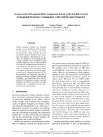
unique mode of life. Three basic optimal designs for fish morphology are derived from
specializations for accelerating, cruising, and maneuvering [4], and they are intimately related
to the locomotion method used (Figure 1‑2). Additionally, because they are primarily mutually
exclusive, no single fish performs optimally in all three functions. However, none of these fish
are specialists in a single activity; instead, they are locomotor generalists incorporating design
elements from all three specialists to varying degrees. [4] and [5] give more information about
how function and morphology work together in swimming fish.
Figure 1-2. Diagram of swimming propulsors and swimming functions
Within the primary classification of MPF and BCF propulsion, additional types of swimming
can be identified for each group using Breder's [2] original classification and nomenclature
(Figure 1‑3). These modes should not be thought of as separate groups. Instead, they should be
seen as prominent points on a continuum. Fish can swim in a variety of ways at the same time
or at different speeds. Median and paired fins are often used together to provide thrust, with
varying contributions from each. This results in smooth trajectories. Several fish also swim in
MPF mode, which gives them more maneuverability, the ability to switch to BCF mode at faster
speeds, and quick acceleration rates, among other things.
5
Figure 1-3. Swimming mode (a): BCF , (b): MPF [17]
BCF propulsion
In undulatory BCF modes, the propulsive wave moves through the fish's body in a different
direction than the overall movement and at a faster rate than the overall speed of the fish when
it swims. Figure 1‑3 shows four undulatory BCF locomotion modes that move in different ways,
such as the one shown in the figure. Each method has a unique wavelength and amplitude
envelope that makes it special. In addition, other modes have different ways of making thrust.
This can be done with a lift-based (vorticity) method and a method that adds more mass to it.
Two main ways to do this: As you can see, this is where the added-mass method has been used
the most. It has been linked to the added-mass process for a long time, but now They know
why. Carangiform and Subcarangiform fish are found in the sea and have vorticity mechanisms
that help them move.
Figure 1-4. Gradation of BCF from (a) Anguilliform through, (b) Subcarangiform, (c)
Crangiform (d) thunniform [18]
6
Anguilliform mode is characterized by large-amplitude undulations that involve the
entire body Figure 1-4(a). A wave that moves your body is at least one full wavelength long,
which means that lateral forces are enough to cancel each other out. This reduces the body's
tendency to recoil when the wave is applied. By shifting the propagation direction of the
propulsive wave, many anguilliform swimmers can swim both backward and forward.
Backward swimming necessitates greater lateral forces and body flexibility [7]. The eel and the
lamprey [8] are well-known examples of this widespread movement style. The sub-carangiform
mode (for example, trout) exhibits similar motions, but the amplitude of the undulations is
limited to the front of the body and only increases in the back of the body. Figure 1-4(b)
Carangiform swimming makes this much clearer because the body undulations are
limited to the last third of the body length Figure 1‑4(c), and a relatively stiff caudal fin gives
propulsion. In general, Carangiform swimmers are faster than their Anguilliform or
Subcarangiform counterparts. However, because of the relative rigidity of their bodies, their
turning and accelerating skills are severely limited. Furthermore, because the lateral forces are
focused on the posterior, there is a greater tendency for the body to rebound.
In the aquatic environment, the Thunniform style has evolved as the most efficient
mode of locomotion. Thrust is generated by the lift-based approach, which allows high cruising
speeds to be maintained for extended periods. It is regarded as a climax in the evolution of
swimming patterns because it is found in a diverse range of vertebrates (teleost fish, sharks, and
marine mammals), all of which have developed in distinct environments. The thunniform mode
is seen in scombrids, which include tuna and mackerel, among other teleost fish. Only the
caudal fin generates more than 90% of the thrust, and the area near the narrow peduncle is
subjected to significant lateral motion. The body is well streamlined to reduce pressure drag,
and the caudal fin is rigid and high, with a crescent-moon shape known as the lunate Figure
1-4(d). Because of the caudal thrust strength, the body shape and mass distribution ensure that
recoil forces are efficiently minimized and that very little sideslipping is caused by the thrusts.
The primary function of Thunniform swimmers is to swim quickly in calm water; however,
other activities such as slow swimming, turning maneuvers, and quick acceleration from
immobile or turbulent water are not well-suited to their design.
Ostraciiform locomotion is the only BCF mode that is entirely oscillatory. It is
distinguished by the caudal fin oscillating in a pendulum-like fashion while the rest of the body
stays essentially solid. Fish that feed in the Ostraciiform mode are frequently enclosed in rigid
bodies and use MPF propulsion to navigate their (usually complicated) environment [9]. When
7
used as an auxiliary locomotion method, caudal oscillations can aid in the creation of thrust at
higher speeds, the maintenance of appropriate rigidity of the body, and prey tracking [6]. The
hydrodynamic adaptations and refinements found in Thunniform swimmers don't show up in
Ostraciiform movement, which has low hydrodynamic efficiency even though it looks similar.
MPF propulsion
Many fish employ undulating fins as alternate propulsors, as well as for maneuvering and
stabilization, regularly. These propulsion systems can also provide sufficient thrust to be
included in the sole means of locomotion at generally low speeds. Certain fish can actively bend
their median fins rays because they have a muscle group (usually six) for each fin ray that allows
them to move with two degrees of freedom. The muscular system of paired fins is even more
complex, allowing them to perform movements like rotations of individual fin rays. Several
reviews of the literature on teleost fin’s structure and properties are provided in [6],[3]. Figure
1‑5 illustrates how their adaptability has played a crucial role in the growth of the undulatory
MPF modes.
Figure 1-5. Growth of the undulatory MPF modes [3]
Some experts say that many fish, like rays, skates, and manta rays, move in the same
way as birds do when they fly. Rajiform mode is found in fish like this. To generate thrust,
vertical undulations must be passed along the extremely large, triangular-shaped pectorals and
flexible. Increasing the amplitude of the undulations from the anterior portion to the apex of the
fin and then decreasing it again toward the posterior part, It is also possible to flap the fins up
and down.
Diodontiform mode moves the animal forward by skipping down the wide pectoral fins
and not causing them to move. As a result, light waves can spread across the fins in two full
wavelengths, and the waves and flapping movements of the fin are often seen together.
Swimming in Amiiform mode is accomplished through undulations of a dorsal fin
(typically long in base), with the body axis being maintained in many cases while swimming.
8
The African freshwater electric eels are the best examples of this characteristic, and they can
be found in large numbers in Africa. It lacks the anal and caudal fins but has many fin rays and
extends along most of the body length before tapering to a posterior point (up to 200).
Because a long-based anal fin moves, Gymnotiform mode can be thought of as the
upside-down version of amiiform mode because it moves to move forward. Gymnotiform mode
is one of the types of amiiform modes that can be used to play games. The dorsal fin isn't usually
there during swimming, and the body is held straight again, like before. Electric eels tend to
keep their bodies rigid while swimming, which has long been thought necessary because they
have a system detecting electricity. On the other hand, the fact that undulatory movements don't
make friction drag go up might also be a factor.
In Balistiform locomotion, both the anal and dorsal fins move to make the animal move
forward. This is mainly observed in the Balistidae family. Their distinguishing characteristics
are that their median fins are typically inclined toward one another, whereas their bodies are
generally flat and compressed laterally. These design features have been linked to increased
propulsion efficiency in various studies.
1.3.2 The swimming mechanism of fishes
Studies related to the swimming mechanism of fishes have been ongoing for many years.
Researchers have been interested in understanding how fish are able to swim efficiently through
water, and how this knowledge can be applied to the design of underwater vehicles and robots.
One area of research has focused on the undulating motion of fish fins. In a study, the authors
investigated the factors contributing to the propulsive thrust and efficiency of undulating fins
for various swimming modes. They noted that tissue fibers in the fin of cuttlefish may store
elastic energy during fin bending, allowing the fin to function as a harmonic oscillator and
increasing the efficiency of the fins during locomotion[125].
Another area of research has focused on the morphology of fish and how it affects swimming
performance. In a study developed a model for carangiform swimmers that addressed the
mechanics of both the foil (caudal fin) and the body. The authors noted that the long narrow
peduncle of carangiforms allows the caudal tail fin to be located several chord lengths away
from the main body, which affects the flow field around the fish and its swimming performance
[126].
9
Researchers have also developed mathematical models to describe the effect of sinusoidal
inputs over a cycle of fish locomotion. Leonard’s research derived an average-formula approach
to describe this effect, which is appealing because fish locomotion often involves oscillatory
motions of the fins and body[127]. Li and Saimek developed a Kalman filter-based estimation
scheme that recovers the hydrodynamic potential from a set of pressure measurements along a
fish’s body[128].
Overall, studies related to the swimming mechanism of fishes have provided valuable insights
into the design of underwater vehicles and robots. By understanding how fish are able to swim
efficiently through water, researchers can develop more effective and efficient underwater
technologies.
1.3.3 The Development of Vertebrate Locomotion
An organism, like a vertebrate, is a dynamic system that has changed since it was first created.
However, even though the parts change, the organism works similarly. Self-organization is the
process by which the organism grows and changes in a way that makes sense. This process is
based on genetic, chemical, mechanical, and activity-dependent mechanisms.
All vertebrate brains go through the same stages as they grow. Researchers have found that
synaptogenesis depends on what the animal is doing. This process happens both before and
after the animal is born. So, the adult pattern of brain connections is made possible by processes
that depend on how the brain is used. The function also determines structure.
It is well known that all embryos of vertebrates move around before they are born[19], [20].
But the effects of the pattern of prenatal behavior have only been fully understood in the last
few years[19], [21]–[23]. It has been suggested that these movements during pregnancy could
be how the nervous system connects sensory inputs to specific patterns of muscle activity.
Prenatal movements can be broken down into the following stages[19], [20], [23]:
Pre-Motile Stage: In species like Xenopus Laevis, when fine hair is touched on the head
during the pre-motile stage, right before the animal moves on its own, it bends away from the
stimulus. Roberts[23] says that a reflex pathway is to blame for this bending.
Bending of the head: In the next movement stage, the head moves forward in a way
that isn't coordinated with the rest of the body. This move starts in the neck and doesn't show
any coordination. Like in swimming, a bend to the left doesn't come before an angle to the right.
The way it bends seems to happen at random. The animal's lack of coordination shows that it is
functionally split into two parts, one on each side. Only its head and neck are visible when the
10