Torque Control Part 7 pptx
Bạn đang xem bản rút gọn của tài liệu. Xem và tải ngay bản đầy đủ của tài liệu tại đây (952.51 KB, 20 trang )
Torque Control
110
Fig. 26. Adaptive stator fluxes estimator
Fig. 27. 45(KW) motor behavior with the adaptive stator flux estimator
Induction Motor Vector and Direct Torque Control
Improvement during the Flux Weakening Phase
111
It is possible to combine the two previous estimators. The first one can be used for high
speed, while the second estimator can be used for low speed range. In this case, there is no
need to program the adaptive estimator of the stator fluxes, since it will not work during the
flux weakening phase.
7. Conclusion
This chapter has presented a full study of the magnetic state variation of the induction
motor. Using a finite elements calculation program, it was possible to establish a two-phase
model that takes into account the variation of the saturation level. A very simple resolution
method of this new model was presented. The dynamic response of the new model was
validated by comparing it to the dynamic response of the induction motor given by the
finite element calculation program. After establishing the new model it was possible to
review the advanced control laws like the FOC and the DTC laws. A new saturated FOC law
was developed in order to enhance the dynamic behavior of the motor during the flux
weakening phase, because of the difference between the motor cyclic inductances values
and the values of the cyclic inductances introduced in the controllers. Concerning the DTC
law, it was shown that a small error in the stator resistor value will highly influence the
stator flux estimation, which is done using the stator electric equation. A new stator fluxes
estimator was developed using rotor electric equations. This estimator is less sensitive to the
motor temperature variation, but it is more sensitive to the variation of the saturation level.
An adaptive solution was proposed to tune the estimator parameters according to the
saturation level of the motor. Nevertheless the adaptive part added to the DTC algorithm,
its computation time remains very small comparing to the FOC algorithm that takes into
account the variation of the saturation level. It is important to mention that it is possible to
combine the classical estimator and the new estimator according to the speed range. The
classical estimator can be used at high speed, but at low speed, it is better to use the new
stator flux estimator.
8. References
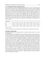
Grotstollen, H. & Wiesing, J. (1995). Torque capability and control of saturated induction
motor over a wide range of flux weakening,
Transaction on Industrial Electronics,
Vol. 42, No. 4, (August 1990) page numbers (374-381).
Vas, P. & Alakula, M. (1990). Field oriented control of saturated induction motors,
IEEE
Transaction on Energy Conversion
, Vol. 5, No. 1, (March 1990) page numbers (218-
224), ISSN 0885-8969.
Kasmieh, T. & Lefevre, Y. (1998). Establishment of two-phase non-linear simulation model
of the dynamic operation of the induction motor,
EPJ European Physical Journal, Vol.
1, No. 1, (January 1998) page numbers (57-66).
Vas, P. (1981). Generalized transient analysis of saturated a.c motors,
Archiv fur
Elektrotechnik
, Vol. 64, No. 1-2, (June 1981) page numbers (57-62).
Kasmieh, T. (2008). Adaptive stator flux estimator for the induction motor Direct Torque
Control,
Proceedings of SPEEDAM 2008, pp. 1239-1241, Ischia, June 2008,
Italy.
Torque Control
112
Blaschke, F. (1972). The principal of field orientation as applied to the new trans-vector
closed-loop control system for rotating field machines,
Siemens Review, (May
(1972).
Kasmieh, T.( 2002), Presentation of a powerful opened simulator for the saturated induction
motor traction system,
Proceedings of SPEEDAM 2002, (June 2002), pp. A1 24-A1 37,
Ravello, June 2002, Italy.
Noguchi, T. & Takahashi, I. (1984).
Quick torque response control of an induction motor
based on a new concept,
IEEE Tech, Vol. RM84-76, (September 1984) page numbers
(61-70).
Depenbrock, M. & Steimel A.(1990). High power traction drives and convertors.
Proc. of
Elect. Drives Symp.’90
, pp. 1–9, Capri,1990, Italy.
C.A, Martins.; T.A, Meynard.; X, Roboam. & A.S, Carvalho2. (1999). A predictive sampling
scale model for direct torque control of the induction machine fed by multilevel
voltage-source inverters.
European Physical Journal-Applied Physics, AP. 5, (1999)
page numbers (51-61).
5
Control of a Double Feed and
Double Star Induction Machine
Using Direct Torque Control
Leila Benalia
Department of electrical Engineering
Batna University, Rue Chahid Med El Hadi boukhlouf
Algeria
1. Introduction
DTC is an excellent solution for general-purpose induction drives in very wide range The
short sampling time required by the TC schemes makes them suited to a very fast torque
and flux controlled drives as well the simplicity of the control algorithm. DTC is inherently
a motion sensor less control method.
2. Objective of the work
This chapter describes the control of doubly fed induction machine (DFIM) and the control
of doubly star asynchronous machine (DSAM), using direct torque control (DTC).
3. Principe du control direct du couple
Direct torque control is based on the flux orientation, using the instantaneous values of
voltage vector.
An inverter provides eight voltage vectors, among which two are zeros (Roys & Courtine,
1995), (Carlos et al., 2005). This vector are chosen from a switching table according to the
flux and torque errors as well as the stator flux vector position. In this technique, we don’t
need the rotor position in order to choose the voltage vector. This particularity defines the
DTC as an adapted control technique of ac machines and is inherently a motion sensor less
control method (Casdei et al., 2001), (Kouang-kyun et al., 2000).
4. Double feed induction machine (DFIM)
In the training of high power as the rolling mill, there is a new and original solution using a
double feed induction motor (DFIM). The stator is feed by a fixed network while the rotor
by a variable supply which can be either a voltage or current source.
The three phase induction motor with wound rotor is doubly fed when, as well as the stator
windings being supplied with three phase power at an angular frequency
s
ω
, the rotor
windings are also fed with three phase power at a frequency
rr
ω
.
Torque Control
114
Under synchronous operating conditions, as shown in (Prescott & Alii., 1958), (Petersson.,
2003) , the shaft turns at an angular velocity
r
ω
, such that:
rsrr
ω
ωω
=
+
The sign on the right hand side is (+) when the phase sequences of the three phase supplies
to the stator and rotor are in opposition and (-) when these supplies have the same phase
sequence. The rotational velocity of the shaft,
r
ω
, is expressed in electric radians per second,
to normalize the number of poles.
4.1 Double feed induction machine modelling
Using the frequently adopted assumptions, like sinusoid ally distributed air-gap flux
density distribution and linear magnetic conditions and considering the stator voltages
( ,
ss
vv
α
β
) and rotor voltages ( ,
rr
vv
α
β
) as control inputs, the stator flux
(
s
,
s
α
β
ΦΦ), and the rotor current (
r
,
r
ii
α
β
) as state variables. In the referential axis fixed in
relation to the stator, the following electrical equations are deduced:
0
0
sss
s
sss
s
VI
R
d
VI
R
dt
α
αα
β
ββ
Φ
⎡
⎤⎡⎤⎡⎤
⎡⎤
=+
⎢
⎥⎢⎥⎢⎥
⎢⎥
Φ
⎣⎦
⎣
⎦⎣⎦⎣⎦
(1)
00
00
rrrr
r
rrrr
r
VI
R
d
VI
R
dt
α
αα α
β
ββ β
ω
ω
ΦΦ
⎡
⎤⎡⎤⎡⎤⎡⎤
⎡⎤ ⎡⎤
=++
⎢
⎥⎢⎥⎢⎥⎢⎥
⎢⎥ ⎢⎥
ΦΦ
−
⎣⎦ ⎣⎦
⎣
⎦⎣⎦⎣⎦⎣⎦
(2)
Expressions of fluxes are given by:
sss r
sss r
rrr s
rrr s
lI MI
lI MI
lI MI
lI MI
α
αα
β
ββ
α
αα
β
ββ
Φ= +
⎧
⎪
Φ= +
⎪
⎨
Φ= +
⎪
⎪
Φ= +
⎩
(3)
The mathematical model is written as a set of equations of state, both for the electrical and
mechanical parts:
dX
XAXBU
dt
•
== +
(4)
Where:
⎥
⎥
⎥
⎥
⎥
⎦
⎤
⎢
⎢
⎢
⎢
⎢
⎣
⎡
Φ
Φ
=
β
α
β
α
s
s
r
r
I
I
X
and
⎥
⎥
⎥
⎥
⎥
⎦
⎤
⎢
⎢
⎢
⎢
⎢
⎣
⎡
=
β
α
β
α
r
r
s
s
V
V
V
V
U
(5)
The matrices A and B are given by:
Control of a Double Feed and Double Star Induction Machine Using Direct Torque Control
115
⎥
⎥
⎥
⎥
⎥
⎥
⎥
⎥
⎥
⎦
⎤
⎢
⎢
⎢
⎢
⎢
⎢
⎢
⎢
⎢
⎣
⎡
−
−
−−
−
−
−
−−−
=
ss
ss
s
r
s
r
r
s
r
s
TT
M
TT
M
MTMT
MMTT
A
1
00
0
1
0
111
111
'
'
δ
δ
ω
δ
δ
δ
ω
ω
δ
δ
δ
δ
ω
δ
(6)
B=
⎥
⎥
⎥
⎥
⎥
⎥
⎥
⎦
⎤
⎢
⎢
⎢
⎢
⎢
⎢
⎢
⎣
⎡
−
−
−
−
0010
0001
1
0
1
0
0
1
0
1
δδ
δ
δδ
δ
r
r
LM
LM
(7)
J
d
dt
Ω
=C
em
-C
r
-K
f
Ω. (8)
Where J is the moment of inertia of the revolving parts, K
f
is the coefficient of viscous
friction, arising from the bearings and the air flowing over the motor, and C
r
is the load
couple.
The equation of the electromagnetic torque is:
3
()
2
esrsr
s
pM
CII
L
α
ββα
=Φ−Φ (9)
The block diagram for the direct torque and flux control applied to the double feed
induction motor is shown in figure 1.The stator flux Ψ
ref
and the torque C
emref
magnitudes
are compared with respective estimated
values and errors are processed through hysteresis-
band controllers.
Stator flux controller imposes the time duration of the active voltage vectors, which move
the stator flux along the reference trajectory, and torque controller determinates the time
duration of the zero voltage vectors, which keep the motor torque in the defined-by
hysteresis tolerance band (Kouang-kyun et al.,2000), ( Xu & Cheng.,1995). Finally, in every
sampling time the voltage vector selection block chooses the inverter switching state, which
reduces the instantaneous flux and torque errors (Presada et al., 1998).
5. Simulation results machine
Figure 2 refer in order, to the variation in magnitude of the following quantities, speed, flux
and electromagnetic torque obtained while starting up the induction motor initially under
no load then connecting the nominal load. During the starting up with no load the speed
reaches rapidly its reference value without overtaking, however when the nominal load is
applied a little overtaking is noticed and the command reject the disturbance. The excellent
dynamic performance of torque and flux control is evident.
Torque Control
116
DFIM
PARK
Transformation
Estimated
Stator flux
Estimated
electromagnetic
Tor
q
ue
ref
φ
1
0
Switching
Table
c
fl
x
ccpl
_
+
-
S
c
S
a
S
b
U
c
i
sa
i
sb
βs
i
αs
i
αs
V
βs
V
βs
i
αs
i
β
φ
s
α
φ
s
sest
φ
emest
C
C
emref
1
-1
0
Network
1
2
3
4
5
6
Load
N
Fig. 1. DTC applied to double feed induction machine
6. Robust control of the IP regulator
a) Speed variation
Figure 3 shows the simulation results obtained for a speed variation for the values: (Ω
ref
=
157, 100 and 157 rad/s), with the load of 3 N.m applied at t =0.8s. This results show that the
variation lead to the variation in flux and the torque. The response of the system is positive,
the speed follow its reference value while the torque return to its reference value with a little
error.
b) Speed reversal of rated value
The excellent dynamic performance of torque control is evident in figure 4, which shows
torque reversal for speed reversal of (157, -157 rad/s), with a load of 5N.m applied at t=1 s.
The speed and torque response follow perfectly their reference values with the same
response time. The reversal speed leads to a delay in the speed response, to a peak
oscillation the current as well as a fall in the flux magnitude which stabilise at its reference
value.
Control of a Double Feed and Double Star Induction Machine Using Direct Torque Control
117
Angular
speed (rad/s)
Electromagnetic
torque (N.m)
Time (s)Time (s)
Time (s)
Stator flux( Wb)
Fig. 2. Simulation results obtained with an IP regulator
Angular
speed (rad/s)
Time (s)
Electromagnetic
torque (N.m)
Time (s)
Time (s)
Stator flux( Wb)
Fig. 3. Robust control for a speed variation
Torque Control
118
Angular
speed (rad/s)
Time (s)
Electromagnetic
torque (N.m)
Time (s)
Time (s)
Stator flux( Wb)
Fig. 4. Robust control under reversal speed
c) Robust control for load variation
The simulation results obtained for a load variation (C
r
= 3 N.m, 6 N.m) in figure 5, show
that the speed, the torque and the flux are inflated with this variation. Indeed the torque and
the speed follow their reference values.
Angular
speed (rad/s)
Time (s)
Electromagnetic
torque (N.m)
Time (s)
Time (s)
Stator flux( Wb)
Fig. 5. Robust control under load variation
Control of a Double Feed and Double Star Induction Machine Using Direct Torque Control
119
d) Robust control of the regulator under stator resistance variation
In order to verified the robustess of the regulator under motor parameters variations we
carried out a test for a variation of 50% in the value of stator resistance at tile t= 1.5s. The
speed is fixed at 157 rad/s and a resistant torque of 5 N.m is applied at t= 1s. Figure 6 shows
the in order the torque response, the current, the stator flux and the speed. The results
indicate that the regulator is very sensitive to the resistance change which results in the
influence on the torque and the stator flux.
Angular
speed (rad/s)
Time (s)
Electromagnetic
torque (N.m)
Time (s)
Time (s)
Stator flux( Wb)
Fig. 6. Robust control under stator resistance variation
7. Double star induction machine (DSIM)
For the last 20 years the induction machines with a double star have been used in many
applications for their performances in the power fields because of their reduced pulsation
when the torque is minimum (Kalantari et al.,2002).The double stator induction machine
needs a double three phase supply which has many advantages. It minimise the torque
pulsations and uses a power electronics components which allow a higher commutation
frequency compared to the simple machines. However the double stator induction machines
supplied by a source inverter generate harmonic which results in supplementary losses
(Hadiouche et al., 2000). The double star induction machine is not a simple system, because
a number of complicated phenomena’s appears in its function, as saturation and skin effects
(Hadiouche et al., 2000).
The double star induction machine is based on the principle of a double stators displaced by
α=30
0
and rotor at the same time. The stators are similar to the stator of a simple induction
machine and fed with a 3 phase alternating current and provide a rotating flux.
Each star is composed by three identical windings with their axes spaced by 2π/3 in the
space. Therefore, the orthogonality created between the two oriented fluxes, which must be
Torque Control
120
strictly observed, leads to generate decoupled control with an optimal torque (Petersson.,
2003).
This is a maintenance free machine.
The machine studied is represented with two stars windings: A
s1
B
s1
C
s1
et A
s2
B
s2
C
s2
which
are displaced by 30
α
=
° and thee rotorical phases: A
r
B
r
C
r
.
Star N°1
Star N°2
C
r
B
s1
α
θ
A
s1
A
s2
A
r
B
r
C
s1
C
Rotor
B
s2
Fig. 7. Double star winding representation
8. Double star induction machine modeling
The mathematical model is written as a set of state equations, both for the electrical and
mechanical parts:
[]
[]
[]
,1 1 ,1 ,1
,2 2 ,2 ,2
,,,
.
.
.
abc s s abc s abc s
abc s s abc s abc s
abc r r abc r abc r
d
VRI
dt
d
VRI
dt
d
VRI
dt
⎡
⎤⎡⎤⎡⎤
=+Φ
⎣
⎦⎣⎦⎣⎦
⎡
⎤⎡⎤⎡⎤
=+Φ
⎣
⎦⎣⎦⎣⎦
⎡⎤ ⎡⎤⎡ ⎤
=+Φ
⎣⎦ ⎣⎦⎣ ⎦
(1)
J
d
dt
Ω
=C
em
-C
r
-K
f
Ω. (2)
Where:
J is the moment of inertia of the revolving parts.
K
f
is the coefficient of viscous friction, arising from the bearings and the air flowing over the
motor.
C
em
is the electromagnetic torque.
The electrical state variables are the flux, transformed into vector [
Φ
] by the “dq”
transform, while the input are the “dq” transforms of the voltages, in vector [V].
[][][] [][]
. B .v
d
A
dt
Φ= Φ +
(3)
Control of a Double Feed and Double Star Induction Machine Using Direct Torque Control
121
[]
1
2
1
2
ds
ds
qs
qs
dr
q
r
Φ
⎡
⎤
⎢
⎥
Φ
⎢
⎥
⎢
⎥
Φ
⎢
⎥
Φ=
Φ
⎢
⎥
⎢
⎥
Φ
⎢
⎥
⎢
⎥
Φ
⎣
⎦
[]
1
2
1
2
ds
ds
qs
qs
v
v
V
v
v
⎡
⎤
⎢
⎥
⎢
⎥
=
⎢
⎥
⎢
⎥
⎢
⎥
⎣
⎦
(4)
The equation of the electromagnetic torque is given by
Cem= p
Lm
Lm Lr
+
(Φ
dr
(i
qs1
+i
qs2
)-Φ
qr
(i
ds1
+i
ds2
)) (5)
The flux equation is:
md a
L
Φ
=
ds1
s1
L
⎛
Φ
⎜
⎝
+
ds2
s2
L
Φ
+
dr
r
L
⎞
Φ
⎟
⎟
⎠
(6)
m
q
a
L
Φ
=
qs1
s1
L
Φ
⎛
⎜
⎝
+
qs2
s2
L
Φ
+
qr
r
L
⎞
Φ
⎟
⎟
⎠
(7)
Given that the “dq”axes are fixed in the synchronous rotating coordinate system, we have:
[]
11 12 13 14 15 16
21 22 23 24 25 26
31 32 33 34 35 36
41 42 43 44 45 46
51 52 53 54 55 56
61 62 63 64 65 66
aaaaaa
aaaaaa
aaaaaa
A
aaaaaa
aaaaaa
aaaaaa
⎡
⎤
⎢
⎥
⎢
⎥
⎢
⎥
=
⎢
⎥
⎢
⎥
⎢
⎥
⎢
⎥
⎢
⎥
⎣
⎦
(8)
[]
1000
0100
0010
0001
0000
0000
B
⎡
⎤
⎢
⎥
⎢
⎥
⎢
⎥
=
⎢
⎥
⎢
⎥
⎢
⎥
⎢
⎥
⎢
⎥
⎣
⎦
(9)
Where:
a
11
= a
33
=
11
2
1
1
sa s
s
s
RL R
L
L
−
a
12
=a
34
=
1
12
sa
ss
RL
LL
Torque Control
122
s
ω
a
13
= a
24
= - a
31
= - a
42
=
a
14
= a
16
=a
23
= a
26
= a
32
=a
35
=a
41
=a
45
=a
53
= a
54
=a
61
=a
62
= 0
a
15
= a
36
=
1
1
sa
rs
RL
LL
, a
21
= a
43
=
2
12
sa
ss
RL
LL
a
22
= a
44
=
21
2
1
2
sa s
s
s
RL R
L
L
−
,
a
25
= a
46
=
2
2
sa
rs
RL
LL
a
51
= a
63
=
1
ra
rs
RL
LL
, a
52
= a
64
=
2
ra
rs
RL
LL
a
55
= a
66
=
2
2
ra r
r
r
RL R
L
L
−
,
a
56
= - a
65
=
g
l
ω
Figure 8 shows the block diagram for the direct torque and flux control applied to the
double star induction motor shown in.
DSIM
2
1
3
4
5 6
Load
Network
PAR
K
Transformation
Switching
Table
Estimated
Star flux
Estimated
electromagnetic
Torque
i
sb
i
sa
S
a
S
b
S
c
β
s
i
α
s
V
β
s
V
α
s
i
β
s
i
α
φ
s
β
φ
s
+
C
emref
_
C
emest
cflx
sest
φ
ref
φ
+
_
N
U
c
Fig. 8. DTC applied to double star induction machine
Control of a Double Feed and Double Star Induction Machine Using Direct Torque Control
123
9. Simulation results
Figure 9 refer in order, to the variation in magnitude of the following quantities, speed,
electromagnetic torque, current and flux obtained while starting up the induction motor
initially under no load then connecting the nominal load. During the starting up with no
load the speed reaches rapidly its reference value without overtaking, however when the
nominal load is applied a little overtaking is noticed and the command reject the
disturbance. The excellent dynamic performance of torque and flux control is evident.
Angular
speed (rad/s)
Time (s)
Electromagnetic
torque (N.m)
Time (s)
Time (s)
Stator flux( Wb)
Fig. 9. Simulation results obtained with an PI regulator
10. Control of the regulator
a) Speed variation
Figure.10 shows the simulation results obtained for a speed variation for the values: (Ω
ref
=
314 and 260 rad/s), with the load of 5 N.m applied at t=1.5s.
These results shows that the variation lead to the variation in flux and the torque. The
response of the system is positive, the speed follow its reference value while the torque
return to its reference value with a little error.
b) Robust control for load variation
Figure.11 shows the simulation results obtained for a load variation (C
r
= 5 N.m, 2.5 N.m).
As can be seen the speed, the torque, the flux and current are influenced by this variation.
The torque and the speed follow their reference values.
We can see that the control is robust from the point of view load variation.
Torque Control
124
Angular
speed (rad/s)
Time (s)
Electromagnetic
torque (N.m)
Time (s)
Time (s)
Stator flux( Wb)
Fig. 10. Robust control for a speed variation
Angular
speed (rad/s)
Time (s)
Electromagnetic
torque (N.m)
Time (s)
Time (s)
Stator flux( Wb)
Fig. 11. Robust control under load variation
Control of a Double Feed and Double Star Induction Machine Using Direct Torque Control
125
c) Robust control of the regulator under star resistance variation
In order to verified the robustess of the regulator under motor parameters variations we
carried out a test for a variation of 50% in the value of star resistance at time t= 1.5s. The
speed is fixed at 314 rad/s and a resistant torque of 5N.m is applied at t= 1s. Figure 6 shows
in order the torque response, the current, the stator flux and the speed. The results indicate
that the regulator is very sensitive to the resistance change which results in the influence on
the torque and the stator flux
Angular
speed (rad/s)
Time (s)
Electromagnetic
torque (N.m)
Time (s)
Time (s)
Stator flux( Wb)
Fig. 12. Robust control under stator resistance variation
11. Conclusion
This chapter presents a control strategy for a double feed induction machine and double star
induction machine based on the direct control torque (DTC) using a PI regulator. The
simulation results show that the DTC is an excellent solution for general-purpose induction
drives in a wide range of power.
The main features of DTC compared to the classical flux oriented control FOC can be
summarized as follows:
• DTC has a simple and a robust control structure.
• DTC operates with closed torque and flux loops but without current controllers.
• DTC needs stator flux and torque estimation and, therefore, is not sensitive to rotor
parameters.
• DTC is inherently a motion sensor less control method.
The simulation results show that the DTC is an excellent solution for general-purpose
induction drives in a very wide power range. The short sampling time required by the DTC
scheme makes it suited to very fast torque and flux controlled drives beside the simplicity of
the control algorithm.
Torque Control
126
However the DTC presents two major problems:
• The absence of the harmonic of the couple restraint (electromagnetic compatibility,
audible noise, variation of the acoustic quality).
• The excitation of some mechanical resonant modes which lead to a serious ageing of the
system.
The DTC applies the same control effort to regulate flux as it does for the torque. Finally, we
believe that the DTC principle will continue to play a strategic role in the development of
high performance motion sensor less AC drives.
12. References
Carlos Ortega, Antoni Arias, Xavier del Toro. (2005). Novel direct torque control for
induction motors using schort voltage vectors of matrix converters.
IEEE
Trans.ind.Appl, pp 1353- 1358, 2005.
Casdei.D, Serra.G, Tani.A,.( 2001). The use of matrix converters in direct torque control of
induction machines.
IEEE Trans.on Industrial Electronics, Vol 48,N 6,.
Hadiouche. D, H.Razik, A.Rezzoug.(2000).
Stady and simulation of space vector PWM
control of Double-Star Induction Motors
.
IEEE-CIEP, Acapulco, Mexico, pp 42-47.
Hadiouche.D, H.Razik, A.Rezzoug.(2000).
Modelling of a double-star induction motor with
an arbitrary shift angle between its three phase windings.
EPE-PEMC, Kosice.
Kalantari.A, M. Mirsalim, H.Rastegar.(2002).
Adjustable speed drive based on fuzzy logic for
a dual three-phase induction machine.
Electrimacs, pp 18-21.
Kouang-kyun La, Myoung-Ho Schin, Dong-Seok Hyun.(2000).
Direct torque control of
induction motor with reduction of torque ripple.
IEEE Trans.ind.Appl, pp 1087 -1092
Petersson.AA, (2003). Analysis, modeling and control of doubly fed induction machine for
wind turbines,”
tutorials thesis, chalmers university of technology, Goteborg, Sweden
Presada.S , E. Chekhet, I Shapoval. (1998).
Asymptotic control of torque and unity stator
side power factor of the doubly fed induction machine.
Proceedings Intern. Conf”
Problems of Electrical Drives.
Alushta, pp 81-86.
Prescott.JC et Alii.( 1958).The Inherent instability of Induction Motor under conditions of
Doubly –Supply.
IEEE Proceedings ,UK, vol.105,pp 319-330.
Radwan,.(2005). Perfect speed tracking of directe torque controlled induction motor drive
using Fuzzy logic.
IEEE Trans.ind.Appl, pp 38-43, 2005.
ROYS et S.COURTINE
. ( 1995). Commande directe du couple d’une machine asynchrone
par le contrôle direct de son flux statorique.
Journal de Physique III,pp.863-
880.France.
Xu. L, W. Cheng. (1995).
Torque and reactive power control of a doubly fed induction
machine by position sensorless scheme.
IEEE Transactions on Industry Applications,
vol 31,no. 3, pp 636-642.
Part 2
Oriented Approach of Recent Developments
Relating to the Control of the Permanent
Magnet Synchronous Motors