C1404 c14
Bạn đang xem bản rút gọn của tài liệu. Xem và tải ngay bản đầy đủ của tài liệu tại đây (123.24 KB, 5 trang )
Designation: C 1404/C 1404M – 98
AMERICAN SOCIETY FOR TESTING AND MATERIALS
100 Barr Harbor Dr., West Conshohocken, PA 19428
Reprinted from the Annual Book of ASTM Standards. Copyright ASTM
Standard Test Method for
Bond Strength of Adhesive Systems Used With Concrete as
Measured by Direct Tension1
This standard is issued under the fixed designation C 1404/C 1404M; the number immediately following the designation indicates the
year of original adoption or, in the case of revision, the year of last revision. A number in parentheses indicates the year of last
reapproval. A superscript epsilon (e) indicates an editorial change since the last revision or reapproval.
Methods for Construction Materials3
1. Scope
1.1 This test method covers the laboratory determination of
the bond strength of adhesive systems used to adhere freshly
mixed mortar to hardened portland-cement concrete.
1.2 The values stated, in either SI units or other units shall
be regarded separately as standard. The values stated in each
system may not be exact equivalents; therefore each system
must be used independently of the other, without combining
values in any way.
1.3 This standard does not purport to address all of the
safety concerns, if any, associated with its use. It is the
responsibility of the user of this standard to establish appropriate safety and health practices and determine the applicability of regulatory limitations prior to use.
3. Summary of Test Method
3.1 Each specimen consists of a base and overlay, bonded
together with the adhesive being tested. The base is half of a
3-in. [75-mm] by 6-in. [150-mm] hardened-concrete cylinder
mounted inside of a steel-pipe nipple. The overlay consists of
freshly mixed mortar placed in a steel-pipe nipple positioned
on top of the base.
3.2 The prepared surface of the base is coated with the
adhesive, onto which freshly mixed mortar is applied. After
curing, the assembly is pulled in tension to measure the bond
strength of the adhesive. The tensile strength is calculated, and
the location of failure is determined visually.
4. Significance and Use
4.1 The bonding properties of adhesives are important for
concrete repair applications. This test method provides a means
to measure the adhesive characteristics of materials used to
bond freshly mixed mortar to hardened concrete.
4.2 In addition to providing information on bond strength,
the location of failure is determined visually and is thus
instructive regarding the weakest element in the composite
tested.
4.3 The bond strength that is measured is limited by the
tensile strength of the base concrete and mortar. While an
attempt has been made to choose materials that are strong
enough to force a bond failure, there may be cases where
failure occurs in concrete or mortar. In these situations, the
actual bond strength exceeds the measured result.
2. Referenced Documents
2.1 ASTM Standards:
A 333/A 333M Specification for Seamless and Welded
Steel Pipe for Low-Temperature Service2
C 33 Specification for Concrete Aggregates3
C 39 Test Method for Compressive Strength of Cylindrical
Concrete Specimens3
C 42 Test Method for Obtaining and Testing Drilled Cores
and Sawed Beams of Concrete3
C 109 Test Method for Compressive Strength of Hydraulic
Cement Mortars using 2-in. [50 mm] Cube Specimens4
C 150 Specification for Portland Cement3
C 171 Specification for Sheet Materials for Curing Concrete3
C 192 Practice for Making and Curing Concrete Specimens
in the Laboratory3
C 305 Practice for Mechanical Mixing of Hydraulic Cement
Pastes and Mortars of Plastic Consistency4
C 494 Specification for Chemical Admixtures for Concrete3
C 881 Specification for Epoxy-Resin-Base Bonding Systems for Concrete3
C 670 Practice for Preparing Precision Statements for Test
5. Apparatus
5.1 Testing Machine—The testing machine shall be of the
hydraulic or screw-type and capable of measuring tensile loads
up to 5000 lbf [22 kN] in increments of 45 lbf [200 N] at rates
described in 9.3.
5.2 Steel-Pipe Nipples—The steel-pipe nipples shall conform to Specification A 333/A 333M, be nominally 3 in. [75
mm] in diameter by 3 in. [75 mm] long Schedule 40, threaded;
two per specimen. The inside surface of the steel-pipe nipples
shall be clean and free of oil or other contaminants that could
inhibit bond. The inside surface shall be sandblasted to gray
metal condition.
5.3 Steel-Pipe Cap—Two steel-pipe caps nominally 3 in.
1
This test method is under the jurisdiction of ASTM Committee C-9 on Concrete
and Concrete Aggregates, and is the direct responsibility of Subcommittee C09.25
on Organic Materials for Bonding, Patching, and Decking.
Current edition approved Sept. 10, 1998. Published April 1999.
2
Annual Book of ASTM Standards, Vol 01.01.
3
Annual Book of ASTM Standards, Vol 04.02.
4
Annual Book of ASTM Standards, Vol 04.01.
1
C 1404/C 1404M
saw blade and plain water as the only cutting fluid.
5.11 Cylinder Molds—The cylinder molds shall be 3-in.
[75-mm] diameter by 6-in. [150-mm] long, as described in
Practice C 192.
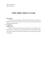
[75 mm] in diameter, and threaded to fit the steel-pipe nipple
molds. Each cap shall be fitted with a steel rod or eye bolt with
at least one universal joint for connection to the testing
machine. The assembly shall have a tensile capacity of at least
5000 lbf [22 kN]. See Fig. 1 for details of preparation.
5.4 Base Assembly—Concrete cylinder and steel pipe
nipple, prepared according to Section 7; one for each specimen.
5.5 O-rings—Rubber, 2-7⁄8 in. [73 mm] inside diameter3
3-1⁄4 in. [83 mm] outside diameter; 3⁄16 in. [5 mm] thick; one for
each specimen.
5.6 Concrete Mixer—As described in Practice C 192.
5.7 Mixer, Bowl, and Paddle—A mechanical mortar mixer,
as described in Practice C 305.
5.8 Small Tools—Tools and items such as a straightedge,
scoops, rubber gloves, and metal mixing bowls.
5.9 Tamping Rod—The tamping rod shall be a round steel
rod, 3⁄8 in. [10 mm] in diameter, conforming to Practice C 192.
5.10 Saw, as described in Test Method C 42, with diamond
6. Materials
6.1 Cement—The cement shall be portland cement meeting
the requirements of Specification C 150.
6.2 Aggregate—The aggregate shall conform to Specification C 33; the coarse aggregate shall conform to Size No. 7.
6.3 Mortar—Prepare and test the mortar in accordance with
Test Method C 109, and each specimen tested shall have a
compressive strength of at least 4500 psi [31 MPa] at seven
days age.
6.4 Concrete—The concrete shall be non air-entrained,
prepared and cured in accordance with Practice C 192, tested
according to Test Method C 39, and each specimen tested shall
have a compressive strength of at least 6000 psi [41 MPa] at 28
FIG. 1 Pipe Cap Detail
2
C 1404/C 1404M
tions for thickness and procedure, including moisture condition
of substrate.
8.4 Mix mortar as described in Test Method C 109. Fill the
nipple in two equal layers, and rod the mortar with 25 strokes
per layer. Strike off the surface with a trowel and cover with
polyethylene film.
8.5 Prepare a minimum of three specimens per test age.
8.6 Moist cure the specimens according to Practice C 192.
days. Water-reducing admixtures, meeting Specification C 494,
may be used.
6.5 For the purpose of qualifying the reference mortar and
concrete, compressive strengths of all specimens tested shall
exceed the minimum stated.
6.6 Abrasive Paper—Sandpaper, emery cloth, or other abrasive paper of grit No. 100.
6.7 Tape—Plastic tape, minimum 2 in. [50 mm] wide.
6.8 Epoxy—Type V, Grade 1 epoxy resin, Specification
C 881, shall have low enough viscosity to flow into the annular
space between the concrete base cylinder and steel-pipe nipple.
9. Procedure
9.1 Remove the tape from the specimens.
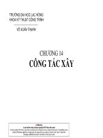
9.2 Screw the pipe caps (Fig. 1) onto the ends of the
specimen (Fig. 2) and connect to the testing machine (see Fig.
3).
9.3 Set the testing machine so the specimen can be loaded
into tension, at least 5000 lbf [22 kN] maximum load capability. For screw type, set cross-head speed at 0.04 in/min [1.0
mm/min]; for hydraulic type, load at 5 6 2 psi/s [35 6 15
kPa/s].
9.4 Load the specimen at constant rate until failure.
NOTE 1—A hot-air blower to heat the pipe nipple has been found useful
to increase flow of the epoxy adhesive between the pipe and the concrete
cylinder.
6.9 Sealant—Capable of sealing the rubber to the concrete
to prevent the flow of the epoxy adhesive; an example is RTV
silicone rubber.
6.10 Polyethylene Film—Meeting Specification C 171 and
having a minimum thickness of 4 mil [0.1 mm].
7. Base Assembly Preparation
7.1 Prepare concrete as described in 6.4 and place in the
cylinder molds, 3-in. [75-mm] diameter by 6-in [150-mm]
long.
7.2 Cure in accordance with Practice C 192 except that
moist curing shall be continuous for 28 days. After this time,
and until the cylinders are cut, they shall be stored at 73.4 6
3.0°F [23 6 2°C] and 50 6 10 % R.H.
7.3 Not more than seven days after completing the curing
cycle, cut the cast cylinders so that two cylinders, 3 in. [75
mm] diameter by nominally 3 in. [75 mm] long, are produced.
Take care that the edges are not chipped during the cutting
operation. Discard any half-cylinders with chips or defects
estimated to be greater than 5 % of the cross-sectional area.
Store the acceptable half-cylinders with the cut surface down,
on a clean, dry surface, at 73.4 6 3.0°F [23 6 2°C] and 50 6
10 % R.H. until used.
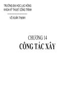
7.4 Place a half-cylinder, cut end down, on a clean, nonporous surface and position the O-ring so that it rests snugly
against the clean surface. Seal the O-ring to the side of the
concrete half-cylinder with sealant. Before the sealant cures,
place a 3 in. [75 mm] long steel pipe nipple onto the cylinder
so that it rests against the O-ring and the sealant. After the
sealant cures, pour epoxy into the annular space between the
nipple and cylinder until the space is full. See Fig. 2 for details.
10. Calculation
10.1 Calculate the tensile strength to the nearest 10 psi [0.1
MPa] as follows:
T 5 P/A
(1)
where:
T 5 tensile strength at failure, psi [MPa],
P 5 maximum applied load, lbf [N], and
A 5 cross sectional area of concrete base.
10.2 Estimate the location of failure in percent of cross
sectional area for each element of the specimen, that is, in
concrete base, at bond line, in mortar overlay. The sum of the
three values must equal 100.
11. Report
11.1 Report the following information:
11.1.1 Identification of specimen,
11.1.2 Identification of type of cement used to make the test
mortar,
11.1.3 Identification of bonding agent tested,
11.1.4 Moisture condition of substrate,
11.1.5 Length of cure of overlay for each set of specimens,
11.1.6 Number of specimens, Mean and Coefficient of
Variation of T for each set, and
11.1.7 Results of test in the following manner:
8. Preparation and Curing of Composite Specimens
8.1 After the epoxy has cured, invert the base assembly so
that the cut surface of the concrete is up. Rub this surface with
the abrasive paper to remove any extraneous material that
could inhibit bond. Wipe this prepared surface with a damp
cloth to remove any dust or powder that may have accumulated.
8.2 Place a 3 in. [75 mm] long nipple on this assembly and
secure it to the bottom nipple with tape around the outside of
both nipples.
8.3 Apply the adhesive being tested to the prepared surface
of the concrete base using the manufacturer’s recommenda-
Location of Failure, % Area
T, Tensile
Strength at
Failure, psi
Specimen No.
[MPa]
In Mortar
Overlay
At Bond Line
In Concrete
Base
12. Precision and Bias
12.1 Single Operator Precision—The single operator within
laboratory and multilaboratory standard deviations, as shown
below, have been found to be the same:
3
C 1404/C 1404M
NOTE 1—(A) Place the concrete cylinder on a clean, flat surface; seal the O-ring to the cylinder with the sealant; (B) Place a pipe nipple over the
concrete cylinder; (C) Pour epoxy adhesive into the space between the cylinder and nipple; (D) after the epoxy adhesive cures, invert the base assembly
and place the second pipe nipple on top.
NOTE 2—Tape is wrapped around the outside of this final assembly to keep the pieces aligned as well as protect the threads from being covered with
the overlay.
FIG. 2 Specimen Preparation
44 psi [0.30 MPa] for 3-day cure
52 psi [0.36 MPa] for 7-day cure
41 psi [0.28 MPa] for 28-day cure
124 psi [0.84 MPa] for 3-day cure
145 psi [1.01 MPa] for 7-day cure
114 psi [0.78 MPa] for 28-day cure
NOTE 2—These numbers represent the (d2s) limit as described in
Practice C 670. Data are from test of specimens that had strengths in the
range of 246 to 522 psi [1.7 to 3.6 MPa].
Therefore, the results of two properly conducted tests from
the same operator or from two different laboratories on similar
batches should not differ from each other by more than shown
below:
12.2 Bias—The test method has no bias because the values
4
C 1404/C 1404M
FIG. 3 Tensile Bond Assembly in Testing Machine
determined can be defined only in terms of the test method.
13. Keywords
13.1 adhesives; bond strength; bonding agents; concrete-
bonding; overlays; tensile bond
The American Society for Testing and Materials takes no position respecting the validity of any patent rights asserted in connection
with any item mentioned in this standard. Users of this standard are expressly advised that determination of the validity of any such
patent rights, and the risk of infringement of such rights, are entirely their own responsibility.
This standard is subject to revision at any time by the responsible technical committee and must be reviewed every five years and
if not revised, either reapproved or withdrawn. Your comments are invited either for revision of this standard or for additional standards
and should be addressed to ASTM Headquarters. Your comments will receive careful consideration at a meeting of the responsible
technical committee, which you may attend. If you feel that your comments have not received a fair hearing you should make your
views known to the ASTM Committee on Standards, 100 Barr Harbor Drive, West Conshohocken, PA 19428.
5