Advances in Analog Circuits Part 6 pptx
Bạn đang xem bản rút gọn của tài liệu. Xem và tải ngay bản đầy đủ của tài liệu tại đây (474.36 KB, 30 trang )
Fresh Yield
Optimization
by WiCkeD
Circuit Simulation
with
Fresh Netlist
Lifetime Yield
Optimization
by WiCkeD
Circuit Simulation
with
Degraded Netlist
RelXpert
initial d
d for optimal yield
Fresh sizing rules
check
Fresh sizing rules
check
Degraded sizing rules
check
d for optimal yield and reliability
Fig. 5. The new design flow with reliability optimization.
the degraded netlist generated by RelXpert. Note that for each internal optimization loop,
an updated netlist from WiCkeD will be given to RelXpert to obtain a renewed version of
degraded netlist. During this step, both the fresh and degraded sizing rules are checked to
ensure the correct functionality of the circuit both at fresh time and after degradation. The
final obtained design parameters d for optimal yield and reliability are the resulting solution
of the design flow.
Fresh yield optimization step ensures that the smaller worst-case distances will be increased,
thus the fresh design is centered such that it is already less sensitive to parameter drift. This
provides a reasonable starting point for lifetime yield optimization, since the influence of
parameter degradation on the performance and yield is kept at minimum level.
After the lifetime yield optimization, optimized design parameters are obtained such that
any decreasing worst-case distances during lifetime are increased again as much as possible.
The design is centered now such that the most degradation-sensitive worst-case distance will
be kept maximum. The resulting design solution is thus optimal considering both process
variations and lifetime degradations.
8. Prediction: Speed up the β
w
(t) evaluation
In this section, a prediction model of lifetime worst-case distance in time domain is presented
to speed up the analysis of lifetime yield value. Only performance and statistical parameter
sensitivity analysis are needed, in comparison to the Monte-Carlo simulation method and
numerical optimization solutions. It is based on the linear performance model as follows. The
index i of ith performance in vector f is left out for simplicity. Without loss of generality, only
upper bound f
u
is considered hereafter.
139
Lifetime Yield Optimization of Analog Circuits
Considering Process Variations and Parameter Degradations
8.1 Linear performance model
At any time t during the lifetime, the first-order Taylor expansion of performance f (t) with
respect to s
(t) from worst-case point s
w,u
in s space is
f
(s(t)) ≡ f (t) ≈ f (s
w,u
(t)) + ∇f (s
w,u
(t))
T
·(s(t) − s
w,u
(t)) (19)
By assuming a linear performance model, the sensitivity of performance over statistical
parameters keeps constant, i.e.,
∇f (s
w,u
(t)) ≡ g (20)
is constant over the entire s space at any time. Thus the level contours of f in s space are
equidistant lines as illustrated in dashed lines in Figure 6.f
(s
w,u
) in (19) is the upper bound
value f
u
. So from (19) the linear performance model at t can be formulated as
f
(t) ≈ f
u
+ g
T
·(s(t) − s
w,u
(t)) (21)
degradation
s2
s1
s0(t)
s
0(t0)
sw,u(t0)
s
w,u(t)
g
Fig. 6. Linear performance model during lifetime degradation in statistical parameter space
(dashed lines are equidistant level contours of f , ellipsoids are level contours of statistical
parameters).
s
w,u
(t) is called worst-case statistical parameter vector at t. It is the statistical parameter vector
where the corresponding performance f reaches its boundary value f
u
at t. It corresponds
to the position in s space where the probability of occurrence reaches it s maximum in the
non-acceptance region (slashed area in Figure 6). A robust design indicates that such a
probability of occurrence should be kept minimum, i.e., s
w,u
should be positioned furthest
away from s
0
(t) so that it is least sensitive to the s changes which may cause it fall into
non-acceptance region.
Since s
(t) ∼N(s
0
(t), C(t)), the mean and the variance of the linearized performance model
can be formulated from (21) as
μ
( f (t)) = f
u
+ g
T
·(s
0
(t) − s
w,u
(t)) (22)
σ
2
f
(t)
= g
T
·C ·g ≡ σ
2
f
(23)
where (23) is constant over time. Taking the process variation as second order effects on the
sensitivity towards degradation, C
(t) is assumed to be constant, i.e., C(t)=C (Sobe et al.,
2009).
140
Advances in Analog Circuitsi
Considering parameter degradation from t
0
to t, a first-order Taylor approximation of μ( f (t))
with respect to t from t
0
can be expressed as
μ( f (t)) = μ( f (t
0
)) +
∂μ
f
∂t
|
t
0
·(t − t
0
) (24)
From (22) we have
μ
( f (t
0
)) = f
u
+ g
T
·(s
0
(t
0
) −s
w,u
(t
0
)) (25)
and
∂μ
f
∂t
|
t
0
= g
T
·
∂s
0
(t)
∂t
|
t
0
−
∂s
w,u
(t)
∂t
|
t
0
(26)
It can be observed from (26) that the product
g
T
·
∂s
w,u
(t)
∂t
|
t
0
(27)
remains zero, since the two vectors g and
∂s
w,u
(t)
∂t
|
t
0
are orthogonal to each other. This is easy to
understand because during the degradation of s parameters, the worst-case point s
w,u
moves
along the performance boundary f
u
, as can be observed in Figure 6, while the performance
gradient g always points to the direction that is vertical to that boundary in the performance
model.
So (26) becomes
∂μ
f
∂t
|
t
0
= g
T
·
∂s
0
(t)
∂t
|
t
0
(28)
and (24) can be further expressed as
μ( f (t)) = f
u
+ g
T
·(s
0
(t
0
) −s
w,u
(t
0
)) + g
T
·
∂s
0
(t)
∂t
|
t
0
·(t − t
0
) (29)
8.2 Prediction of β
w,u
(t)
To predict β
w,u
(t), a first-order Taylor expansion of β
w,u
(t) with respect to t from t
0
is
β
w,u
(t)=β
w,u
(t
0
)+
dβ
w,u
(t)
dt
|
t
0
·(t − t
0
) (30)
where the sensitivity part,
dβ
w,u
(t)
dt
|
t
0
can be derived using results from Section 8.1 as follows.
Since at the worst-case point s
w,u
(t), the corresponding level contour of s(t) is
β
2
w,u
(t)=(s
w,u
(t) − s
0
(t))
T
·C
−1
·(s
w,u
(t) − s
0
(t)) (31)
It touches the performance boundary at s
w,u
(t), which means the orthogonal on (31) is parallel
to g:
C
−1
·(s
w,u
(t) − s
0
(t)) = λ · g (32)
Inserting (32) into (31) we have
β
2
w,u
(t)=λ
2
·g
T
·C ·g (33)
By taking λ from (33) into (32) we obtain
(s
w,u
(t) − s
0
(t)) =
β
w,u
(t)
g
T
·C ·g
·C ·g (34)
141
Lifetime Yield Optimization of Analog Circuits
Considering Process Variations and Parameter Degradations
Then (34) is taken back into (22):
μ
( f (t)) = f
u
− β
w,u
(t) ·
g
T
·C ·g (35)
so that the worst-case distance at t can be expressed as
β
w,u
(t)=
f
u
−μ( f (t))
g
T
·C ·g
(36)
Then from (36) and (29) the worst-case distance degradation rate can be formulated as
dβ
w,u
(t)
dt
|
t
0
= −
1
σ
f
·g
T
·
∂s
0
(t)
∂t
|
t
0
(37)
which differs from (5) in (Sobe et al., 2009). From (37) it is clear that the evaluation of the
worst-case distance degradation rate for a performance upper bound involves only multiple
sensitivity evaluations which can be carried out efficiently. Especially in our case, both σ
f
and
g remain constant, requiring an one-time evaluation only. The sensitivity of s
0
(t) over t is
calculated by finite-difference approximation. The values of s
0
(t) at respective time points are
obtained from exemplary aging simulator in our experiment described in Section 7, then the
corresponding sensitivity and the worst-case distance degradation rate can be evaluated.
Thus, by taking (37) back into (30), the values of β
w,u
(t) at time t can be predicted
efficiently without searching for the worst-case statistical parameters s
w,u
(t) through iterative
optimization method.
9. Experimental results
Vin+Vin-
Ibias
Vdd
Vss
Vout
MP3 MP4 MP5
MP1 MP2
MN1 MN2
MN3
Cmiller
Fig. 7. Circuit topology of Miller OpAmp used in the experiment.
The circuit structure of the two stage Miller OpAmp used in the experiment is shown in Figure
7. The first stage is the differential stage, with the input differential pair, consisting of PMOS
MP1 and MP2, and its active load, a current mirror consisting of NMOS MN1 and MN2. The
second stage is a CMOS inverter with an NMOS MN3 as driver and a PMOS MP5 as its active
load.
It is clear from the circuit structure that certain sizing constraints on transistors concerning the
node voltages impose certain stress levels of each transistor.
142
Advances in Analog Circuitsi
9.1 Results of the new design flow
yield-optimal reliability-optimal
fresh 10 years 10 years fresh
Gain≥80dB 4.0 3.9 3.9 3.9
Slew Rate ≥ 3V/μs 4.2 1.9 3.4 5.8
GBW ≥ 2MHz 5.8 5.7 5.8 5.9
Phase Margin≤ 120deg 5.2 4.3 5.1 5.9
Power≤ 2mW 5.9 5.8 6.2 6.6
CMRR≥80dB 3.4 2.2 3.3 4.2
Relative Area 100% 107%
Lifetime Yield 99.96% 94.50 % 99.93% 99.99%
Table 2. Experimental results of the new design flow with reliability optimization.
We apply the new design flow in Figure 5 to the Miller OpAmp as introduced above. One
of the stop criteria of the tool WiCkeD during fresh or lifetime yield optimization process,
the maximum yield difference between two consecutive iterations, is set to 0.1%. That is,
the fresh or lifetime yield optimization stops if the improvement of the yield value between
two consecutive iterations is smaller than 0.1%. A 180nm technology is used with a supply
voltage of 1.7V. The circuit is degraded to time t=10 years with example AgeMOS degradation
model parameters inside RelXpert. The covariance matrix of statistical parameters is assumed
to be constant over time. Table 2 shows the simulation results. Six of the performances are
considered here, namely, DC Gain, Rising Slew Rate (SR), Gain-Bandwidth Product(GBW),
Phase Margin, Power and Common-Mode Rejection Ratio (CMRR).
From result of fresh yield optimization we can see that the fresh circuit design is centered with
99.96% fresh yield, the corresponding design parameters are initial d at t
0
. After degradation
to 10 years with the same design parameters, all of the performances and worst-case distances
will degrade, as well as the lifetime yield, which is only 94.50% now. Then a design centering
on the degraded circuit is performed during lifetime yield optimization step. The result
shows that the degraded circuit will have a lifetime yield of 99.93% with increased worst-case
distances. Thus a design solution d for optimal yield and reliability is found.
Verification result on last column shows that with this optimized design, fresh circuit at t
0
will
be centered to a better position in terms of both fresh yield and lifetime yield. The fresh yield
is 99.99%, and almost all of the worst-case distances here are much bigger compared to the
fresh design where no degradation is considered.
For the price we pay for the more robust circuit, the approximated total area of the circuit
layout is evaluated. For the area of a transistor, it is simply the product of the width and the
length. For the area of the Miller capacitor, it is transformed into the corresponding area by a
constant. The results in Table 2 show that 7% more relative layout area is needed for the more
robust circuit.
143
Lifetime Yield Optimization of Analog Circuits
Considering Process Variations and Parameter Degradations
9.2 Results of the prediction model
To verify the prediction model of (30), the lifetime worst-case distance values obtained from
the tool WiCkeD and the prediction model are compared for two performances, SR and
CMRR. The comparison results and relative errors at different t’s are plotted in Figure 8 and
Figure 9. It is clear from the results that the prediction model can track the β
w
(t) degradation
with an acceptable error. For the simulation time, it takes five minutes on average for WiCkeD
to evaluate one β
w
(t) for one performance at t, while using the prediction model it takes only
about forty seconds. A clear speedup about eight times is observed.
1.4
1.6
1.8
2.0
2.2
2.4
2.6
2.8
2468
Year
Lifetime worst-case distance
of SR
Accurate
Prediction
(a) Comparison of the accurate and
predicted values of β
w
(t) at different t
0.00
0.01
0.02
0.03
0.04
0.05
0.06
0.07
0.08
2468
Year
Relative error
(b) Relative error of the prediction
Fig. 8. Prediction results on SR
2.0
2.2
2.4
2.6
2.8
3.0
3.2
3.4
2468
Year
Lifetime worst-case
distance of CMRR
Accurate
Prediction
(a) Comparison of the accurate and
predicted values of β
w
(t) at different t
0.00
0.02
0.04
0.06
0.08
0.10
0.12
2468
Year
Relative error
(b) Relative error of the prediction
Fig. 9. Prediction results on CMRR
10. Conclusion
As semiconductor technology continuously scales, the joint effects of manufacturing process
variations and parameter lifetime degradations have been a major concern for analog circuit
designers, since the deviation of performance values from the nominal ones will impact both
the fresh yield and lifetime yield.
In this chapter, a new analog design flow with reliability optimization is presented. The effect
of both process-induced parameter variation and time-dependent parameter degradation
can be analyzed automatically. The remaining lifetime yield of the designed circuit can
be predicted and optimized early in the design phase. After lifetime yield optimization,
simulation results show that a more reliable design is achieved, tolerant of both process
variation and lifetime degradation.
A prediction model for the lifetime worst-case distances is proposed to speed up the analysis
of lifetime worst-case distance values. The experimental results show that the model can
144
Advances in Analog Circuitsi
effectively evaluate during design phase the remaining lifetime yield of the circuits after
degradation occurs in their lifetime.
11. References
Alam, M. A., Kufluoglu, H., Varghese, D. & Mahapatra, S. (2007). A comprehensive model for
PMOS NBTI degradation: Recent progress, Microelectronics Reliability 47(6): 853–862.
Alam, M., Kang, K., Paul, B. & Roy, K. (2007). Reliability-and process-variation aware design
of VLSI circuits, Proceedings of the 14th IEEE International Symposium on the Physical
and Failure Analysis of Integrated Circuits (IPFA), Bangalore, India, pp. 17–25.
Antreich, K., Eckmueller, J., Graeb, H., Pronath, M., Schenkel, F., Schwencker, R. & Zizala, S.
(2000). WiCkeD: Analog circuit synthesis incorporating mismatch, Proceedings of the
IEEE Custom Integrated Circuits Conference (CICC), Orlando, USA, pp. 511–514.
Antreich, K., Graeb, H. & Wieser, C. (1994). Circuit analysis and optimization driven by
worst-case distances, IEEE Transactions on Computer-Aided Design of Integrated Circuits
and Systems 13(1): 57–71.
Eshbaugh, K. (1992). Generation of correlated parameters for statistical circuit simulation,
IEEE Transactions on Computer-Aided Design 11(10): 1198–1206.
Gielen, G., De Wit, P., Maricau, E., Loeckx, J., Martín-Martínez, J., Kaczer, B., Groeseneken,
G., Rodríguez, R. & Nafría, M. (2008). Emerging yield and reliability challenges
in nanometer CMOS technologies, Proceedings of the Design, Automation and Test in
Europe (DATE), Munich, Germany, pp. 1322–1327.
Graeb, H. (2007). Analog Design Centering and Sizing, Springer, The Netherlands.
Hu, C., Tam, S., Hsu, F., Ko, P., Chan, T. & Terrill, K. (1985). Hot-electron-induced MOSFET
degradation– model, monitor, and improvement, IEEE Journal of Solid-State Circuits
20(1): 295–305.
Jha, N., Reddy, P., Sharma, D. & Rao, V. (2005). NBTI degradation and its impact for analog
circuit reliability, IEEE Transactions on Electron Devices 52(12): 2609–2615.
Liu, Z., McGaughy, B. & Ma, J. (2006). Design tools for reliability analysis, Proceedings of the
ACM/IEEE Design Automation Conference (DAC), San Francisco, USA, pp. 182–187.
Lu, Y., Shang, L., Zhou, H., Zhu, H., Yang, F. & Zeng, X. (2009). Statistical reliability
analysis under process variation and aging effects, Proceedings of the ACM/IEEE
Design Automation Conference (DAC), San Francisco, USA, pp. 514–519.
Maricau, E. & Gielen, G. (2009). Efficient reliability simulation of analog ICs including
variability and time-varying stress, Proceedings of the Design, Automation and Test in
Europe (DATE), Nice, France, pp. 1238–1241.
Maricau, E. & Gielen, G. (2010). Variability-aware reliability simulation of mixed-signal ICs
with quasi-linear complexity, Proceedings of the Design, Automation and Test in Europe
(DATE), Dresden, Germany, pp. 1094–1099.
Martin-Martinez, J., Rodríguez, R., Nafria, M. & Aymerich, X. (2009). Time-dependent
variability related to BTI effects in MOSFETs: Impact on CMOS differential
amplifiers, IEEE Transactions on Device and Materials Reliability 9(2): 305–310.
Massier, T., Graeb, H. & Schlichtmann, U. (2008). The sizing rules method for CMOS
and bipolar analog integrated circuit synthesis, IEEE Transactions on Computer-Aided
Design of Integrated Circuits and Systems 27(12): 2209–2222.
Nassif, S. R. (2008). Process variability at the 65nm node and beyond, Proceedings of the IEEE
Custom Integrated Circuits Conference (CICC), San Jose, USA, pp. 1–8.
145
Lifetime Yield Optimization of Analog Circuits
Considering Process Variations and Parameter Degradations
Pan, X. & Graeb, H. (2009). Degradation-aware analog design flow for lifetime yield analysis
and optimization, Proceedings of the 16th IEEE International Conference on Electronics,
Circuits and Systems (ICECS), Yasmine Hammamet, Tunisia, pp. 667–670.
Pan, X. & Graeb, H. (2010). Reliability analysis of analog circuits by lifetime yield prediction
using worst-case distance degradation rate, Proceedings of the 11th IEEE International
Symposium on Quality Electronic Design (ISQED), San Jose, USA, pp. 861–865.
Rauch, S. E. (2002). The statistics of NBTI-induced V
T
and β mismatch shifts in pMOSFETs,
IEEE Transactions on Device and Materials Reliability 2(4): 89–93.
Schroder, D. K. & Babcock, J. A. (2003). Negative bias temperature instability: Road to cross
in deep submicron silicon semiconductor manufacturing, Jounal of Applied Physics
94(1): 1–18.
Sobe, U., Rooch, K., Ripp, A. & Pronath, M. (2009). Robust analog design for automotive
applications by design centering with safe operating areas, IEEE Transactions on
Semiconductor Manufacturing 22(2): 217–224.
Tu, R., Rosenbaum, E., Chan, W., Li, C., Minami, E., Quader, K., Ko, P. & Hu, C.
(1993). Berkeley reliability tools-BERT, IEEE Transactions on Computer-Aided Design
of Integrated Circuits and Systems 12(10): 1524–1534.
Vaidyanathan, B., Oates, A. & Xie, Y. (2009). Intrinsic NBTI-variability aware statistical
pipeline performance assessment and tuning, Proceedings of the IEEE/ACM
International Conference on Computer-Aided Design, San Jose, USA, pp. 164–171.
Vaidyanathan, B., Oates, A., Xie, Y. & Wang, Y. (2009). NBTI-aware statistical circuit delay
assessment, Proceedings of the 10th International Symposium on Quality Electronic Design
(ISQED), San Jose, USA, pp. 13–18.
Wang, W., Reddy, V., Krishnan, A., Vattikonda, R., Krishnan, S. & Cao, Y. (2007). Compact
modeling and simulation of circuit reliability for 65-nm CMOS technology, IEEE
Transactions on Device and Materials Reliability 7(4): 509–517.
Wang, W., Reddy, V., Yang, B., Balakrishnan, V., Krishnan, S. & Cao, Y. (2008). Statistical
prediction of circuit aging under process variations, Proceedings of the IEEE Custom
Integrated Circuits Conference (CICC), San Jose, USA, pp. 13–16.
Yan, B., Qin, J., Dai, J., Fan, Q. & Bernstein, J. (2009). Reliability simulation and circuit-failure
analysis in analog and mixed-signal applications, IEEE Transactions on Device and
Materials Reliability 9(3): 339–347.
146
Advances in Analog Circuitsi
7
Linear Analog Circuits Problems by
Means of Interval Analysis Techniques
Zygmunt Garczarczyk
Silesian University of Technology, Gliwice
Poland
1. Introduction
Inevitable fluctuations in the manufacturing processes and environmental operating
conditions of linear analog circuits cause circuit parameters to vary about their nominal
target values. The mathematical model of an engineering system evaluated by a transfer
function (e.g. of an active and even passive circuit) never describes exactly the system’s
behavior. The changes in the performance of linear circuit due to the variations in circuit
parameters are of great practical importance in engineering analysis and design. The
tolerance problem for linear analog circuit have been extensively studied and many results
have been published, e.g. (Antreich et al., 1994; Spence & Soin, 1997). Because of
uncertainties, the values of the parameters of a given circuit may be treated as belonging to
some intervals. In recent years, interval analysis becomes powerful tool for tolerance
computations of some design problems (Kolev et al., 1988; Femia & Spagnuolo, 1999).
Some results have been reported using algorithms for linear interval equations for
solving tolerance problems (Tian et al., 1996; Garczarczyk, 1999; Shi et al., 1999; Tian & Shi,
2000).
The structure of the chapter is the following: section 2 explains an interval analysis
techniques for linear analog tolerance problem. In that approach we are interested in
calculation tolerances (the range of values) for real and imaginary part of transfer function
with respect to change of one parameter of the circuit. Section 3 deals with the problem of
computing the frequency response of an uncertain transfer function whose numerator and
denominator are interval polynomials. Studying a solution set of corresponding 2×2 linear
interval equation one can obtain bounds on the frequency response. Using Kharitonov
polynomials family and complex interval division it’s also possible to evaluate the bounds.
In this section we compare results obtained by applying presented approaches. Numerical
studies are also reported in order to illustrate presented methods.
2. Evaluation of linear circuits tolerances
The objective of this section is to develop the interval analysis techniques for linear analog
circuit tolerance problem. In that approach we can compute effectively tolerances for real
and imaginary parts of the transfer function with respect to change of one parameter of a
circuit.
Advances in Analog Circuits
148
2.1 Bilinear and biquadratic form of a circuit function
The functional dependence of circuit performance on the designable parameters is known
implicitly through the circuit transfer function. If the dependence on the R, L, C elements
and on the controlled sources is investigated, the transfer function is a quotient of two linear
polynomials, i.e., a bilinear relation, is arrived at. We have the following well-known result:
)s(xD)s(C
)s(xB)s(A
)x,s(M
)x,s(L
)x,s(F
+
+
== (1)
In the above equation the symbol x denotes dependence on the network element parameter
(R or L or C or gain of the controlled source). A(s), B(s), C(s) and D(s) are functions of the
complex frequency s. They depend on kind of transfer function and on the structure of a
circuit examined. A similar biquadratic relation was derived for the dependence on the ideal
transformer ratio n, on the ideal gyrator resistance r and on the conversion factor k of the
ideal negative impedance converter (Geher, 1971). The transfer function has the following
form:
)s(Gx)s(xE)s(D
)s(Cx)s(xB)s(A
)x,s(M
)x,s(L
)x,s(F
2
2
++
++
==
(2)
A(s), B(s), etc. are depending on the type of the transfer function and the topology of the
circuit. For some fixed frequency transfer function can be represented by its real and
imaginary part, i.e.
)x,(M
)x,(L
j
)x,(M
)x,(L
)x,j(F)x(F
1
2
1
1
ω
ω
+
ω
ω
=ω=
(3)
Here L
1
(ω,x), L
2
(ω,x), M
1
(ω,x) denote polynomials in x of second order and fourth order
(maximally) for bilinear and biquadratic transfer functions, respectively. We are interested
in calculation tolerance (the range of values) for real and imaginary part of the transfer
function caused by some parameter x ranging in known interval, i.e. x ∈ x = [ x
, x ] .
This one-parameter tolerance problem can be solved by means of the well-known circle
diagram method for bilinear transfer function, unfortunately biquadratic transfer function is
more difficult problem. Here we propose a unified approach to tolerance problem for
bilinear and biquadratic transfer function based on the range evaluation of a rational
function by means of interval analysis techniques.
2.2 Range values of a rational function
Let L(x) be a polynomial of degree n and M(x) a polynomial of degree m so that
f(x) = L(x)/M(x) is a rational function. We want to expand f(x) into its Taylor series
∑
=
−=
k
0i
i
0i
)xx(c)x(f (4)
For computing the first k Taylor coefficients of f(x) at some point x
0
where M(x
0
) ≠ 0, we
start by developing the polynomial L(x) into its Taylor series about the point x
0
Linear Analog Circuits Problems by Means of Interval Analysis Techniques
149
∑
=
−=
n
0i
i
0i
)xx(a)x(L (5)
Similarly, let
∑
=
−=
m
0i
i
0i
)xx(b)x(M (6)
Note that max(m,n) = 2 or 4.
Coefficients a
i
and b
i
are obtained directly as
a
i
=L
(i)
(x
0
)/i! , b
i
=M
(i)
(x
0
)/i! , (7)
i = 1,2, ,m(n)
More effectively we can compute them by using the extended Horner scheme (Elden &
Wittmeyer-Koch, 1990).
It was derived in (Garczarczyk, 1995) that one can compute the values of the first k Taylor
coefficients of a rational function by solving a (k + 1)×(k + 1) lower triangular Toeplitz
system of the form:
b
bb
bbb
bbbb
c
c
c
c
a
a
a
a
kkk
0
10
210
210
0
1
2
0
1
2
0
⋅⋅⋅⋅
⋅ ⋅⋅⋅
⋅⋅⋅⋅
⎡
⎣
⎢
⎢
⎢
⎢
⎢
⎢
⎢
⎢
⎢
⎢
⎤
⎦
⎥
⎥
⎥
⎥
⎥
⎥
⎥
⎥
⎥
⎥
⋅
⋅
⋅
⎡
⎣
⎢
⎢
⎢
⎢
⎢
⎢
⎢
⎢
⎢
⎢
⎤
⎦
⎥
⎥
⎥
⎥
⎥
⎥
⎥
⎥
⎥
⎥
=
⋅
⋅
⋅
⎡
⎣
⎢
⎢
⎢
⎢
⎢
⎢
⎢
⎢
⎢
⎢
⎤
⎦
⎥
⎥
⎥
⎥
⎥
⎥
⎥
⎥
⎥
⎥
(8)
Note that for the case k > m(n), the lower triangular Toeplitz system is lower banded.
To compute the values of the Taylor coefficients of a rational function the main work is to
solve the lower triangular Toeplitz system (8). Special structure of Toeplitz systems leads to
the variety of solving algorithms, so they belong to more elaborated linear systems. Because
system (8) is lower triangular for a small k, we can use the usual forward substitution method
for its solving. For large k more efficient method is a variant of Trench algorithm for Toeplitz
band matrices (Trench, 1985). Inversion of a nonsingular Toeplitz matrix of the form
T
b
bb
bbb
bbbb
k
=
⋅⋅⋅⋅
⋅⋅⋅⋅
⋅⋅⋅⋅
⎡
⎣
⎢
⎢
⎢
⎢
⎢
⎢
⎢
⎢
⎢
⎢
⎤
⎦
⎥
⎥
⎥
⎥
⎥
⎥
⎥
⎥
⎥
⎥
0
10
210
210
0
(9)
Advances in Analog Circuits
150
band or not may be computed following:
Let (without loss of generality) b
0
= 1, then
T
-1
= [h
rs
]
k
r,s=0
(10)
is the matrix given by
h
rs
= -ψ
r-s-1
, r = 0,1, ,k , s = 0,1, ,r (11)
with ψ
j
= 0 if j < -1, ψ
-1
= -1, and
∑
−
=
−+
ψ−=ψ
1j
0s
ssj1jj
bb , 0 ≤ j ≤ k – 1 . (12)
Note that matrix T
-1
is also lower triangle Toeplitz matrix and is uniquely determined by its
first column (h
00
, ,h
k0
)
t
= (-ψ
-1
,-ψ
0
, ,-ψ
k-1
)
t
. The solution
[c
0
,c
1
, ,c
k
]
t
= T
-1
[a
0
,a
1
, ,a
k
]
t
(13)
of (8) can be calculated by using the fast Fourier transform.
For any function f(x) which has an interval arithmetic evaluation the range of values of f
over the interval
x
R(f,x) := {f(x)⏐ x ∈ x} (14)
is contained in the interval arithmetic evaluation f(
x), i.e.
R(f,
x) ⊆ f(x) (15)
Additionally, it is strongly dependent on the arithmetic expression which is used for the
interval evaluation of the function (Neumeier, 1990; Moore et al., 2009).
Exact Taylor expansion for a rational function f(x) is following
f(x) = p(x) + r(x) (16)
where
∑
=
α=
k
0i
i
i
x)x(p , with
∑
=
−
−
⎟
⎟
⎠
⎞
⎜
⎜
⎝
⎛
=α
k
ir
ir
0ri
)x(
i
r
c (17)
and
r(x) = f
(k+1)
(x
0
+ ξ(x - x
0
))(x - x
k+1
)/(k + 1)! (18)
ξ ∈ [0,1] , x
0
∈ x (e.g. x
0
= m(x)).
If f(x) : D ⊆ R → R is k + 1 times continuously differentiable, then for all
x ⊆ D it’s fulfilled
(Garczarczyk, 1993):
(inclusion)
R(f,
x) ⊆ V(f,x) := R(p,x) + f
(k+1)
(x)w(x)
k+1
/(k + 1)! (19)
(distance)
q(R(f,
x),V(f,x)) ≤ γw(x)
k+1
, γ ≥ 0 , (20)
Linear Analog Circuits Problems by Means of Interval Analysis Techniques
151
where R(p,x) is the exact range of the polynomial p(x) over x, and
q(R,V) = max(|R
- V|,|R - V|) means distance between intervals R = [ R , R ] and V = [ V , V].
Relation (19) gives the way of range values evaluation: we need to calculate the range of
polynomial and the range of remainder term. It’s seen from (20) that the overestimation of
R(f,
x) by V(f,x) decreases with a power k + 1 of w(x) (width of x), so if f
(k+1)
(x) is bounded we
can omit the remainder term in V(f,
x) and then
R(f,
x) ≈ R(p,x) (21)
2.3 Bernstein polynomials
Estimates for the maximum, resp. the minimum, of the polynomial over x are obtained by
computing Bernstein coefficients.
For some order v of Bernstein polynomial we have (Ratschek & Rokne, 1984)
min B
j
≤ min p(x) ≤ max p(x) ≤ max B
j
, (22)
0 ≤ j ≤ v , x ∈
x ,
where v ≥ k and
(wx
s
t
B
st
t
j
0s
k
st
j
−
==
α
⎟
⎟
⎠
⎞
⎜
⎜
⎝
⎛
=
∑∑
x
⎟
⎟
⎠
⎞
⎜
⎜
⎝
⎛
⎟
⎟
⎠
⎞
⎜
⎜
⎝
⎛
s
v
s
j
)
s
, j = 0,1, ,v (23)
The coefficients B
j
are computed using a following finite difference table
0
2
2
0
2
10
12210
B
BB
BB
BBBBBB
ν
−ν
−ν
ν−ν−ν
Δ
ΔΔ
ΔΔ
$%
"
"""""
"""
(24)
The initial slanted entries are generated basing on coefficients of polynomial p(x) following
∑
=
−
α
⎟
⎟
⎠
⎞
⎜
⎜
⎝
⎛
=Δ
k
rl
rl
l
r0
r
x
r
l
AB , (25)
∑
=
−
−ν
α
⎟
⎟
⎠
⎞
⎜
⎜
⎝
⎛
=Δ
k
rl
rl
l
rr
r
x
r
l
AB (26)
where
1
r
r
r
)(wA
−
⎟
⎟
⎠
⎞
⎜
⎜
⎝
⎛
ν
= x , r = 0,1, ,ν,
]x,x[=x .
The top row of table contains the desired Bernstein coefficients. Finite differences are
computed following
j
1r
1j
1r
j
r
BBB
−
+
−
Δ−Δ=Δ , r > 0, j = 0,1, ,ν. (27)
Advances in Analog Circuits
152
For example
001010
BBBBBB
+
Δ
=
⇒
−
=
Δ
(28)
and
1111
BBBBBB
−νν−ν−νν−ν
Δ−=⇒−=Δ
. (29)
Relations (24) – (29) lead directly to the following scheme of computing of Bernstein
coefficients
%
"
"
"
0
2
)(
10
)()(
210
B
B)(B
B)(B)(B
Δ
↑
Δ+→Δ
↑↑
+
→
+
→
+
++
$
"
"
"
2
2
)(
12
)()(
12
B
B)(B
B)(B)(B
−ν
−
−ν−ν
−−
ν−ν−ν
Δ
↑
Δ←+Δ
↑↑
←
+
←
+
(30)
It’s seen we can develop the algorithm of a parallel computation of Bernstein coefficients
starting from slanted entries. We note that since α
l
= 0 for l > k there is no need to compute
entries
j
r
BΔ
for r > k ; a triangle table turns into trapezium one. In the trapezium table a
bottom row has all entries equal, i.e.
s,BBB
s
s
1
s
0
s
>νΔ==Δ=Δ
−ν
" . (31)
Realisation of scheme (30) leads to the three cases of parallel computation slightly different
according to the value of ν (Garczarczyk, 2002).
2.3 Numerical examples
To illustrate the basic ideas of our approach two examples are considered. The first example
refers to the bilinear transfer function and the second to the biquadratic one. Taylor
coefficients a
i
and b
i
i = 0,1, ,k, k = 2 or 4, were computed by means of extended Horner
scheme. For example, polynomial L(x) was developed by the algorithm written in Pascal-
like code as:
for i = 0,1, ,n
a
i
= coefficient(L(x));
for k = 0,1, n
for i = n-1, n-2, ,k
a
i
= a
i+1
x
0
+ a
i
;
In both examples Toeplitz system (8) is banded and was solved using algorithm based on
Trench’s concept (10) – (13).
EXAMPLE 1. Consider a second-order low-pass filter section of Fig.1, originally proposed
by Sallen and Key.
Linear Analog Circuits Problems by Means of Interval Analysis Techniques
153
A
G
2
G
1
C
1
C
2
U
1
U
2
Fig. 1. Second-order low-pass filter section
Bilinear transfer function considered here is following
21
21
1
21
2
2
2
21
21
1
2
CC
GG
s)
C
GG
)x1(
C
G
(s
CC
GG
x
U
U
)x,s(F
+
+
+−+
==
where x = A.
Assuming G
1
= G
2
= 1 and C
1
= C
2
= 1 for fixed frequency we obtain
)x,(M
3x
j
)x,(M
x)1(
)x,j(F)x(F
2
ω
ω−ω
+
ω
ω−
=ω=
where M(ω,x) = 1+7ω
2
+ω
4
-6ω
2
x+ω
2
x
2
.
We have applied relation (21) for Taylor expansion of degree k = 5 and Bernstein coefficients
of degree v = 10 were used. For x ∈
x = A
0
[1-ε, 1+ε] with A
0
= 1, ε = 0.01 we obtained results
presented in the Table 1. In the second column there are values of the ranges for real and
imaginary part of the transfer function, the third column contains their nominal values.
ω
x ∈
x
X = A
0
0.2 [0.878692,0.899103] + j[-0.372772,-0.367971] 0.888889 - j0.370370
2.0 [-0.127097,-0.122930] + j[-0.168624,-0.164735] -0.125005 - j0.166667
20.0 [-0.024009,-0.023489] + j[-0.002395,-0.002367] -0.023749 - j0.002381
Table 1. Range values of transfer function of Sallen-Key low-pass section
EXAMPLE 2. Consider the gyrator circuit with feedback shown in Fig.2.
u
2
u
1
r
Y
Z
Fig. 2. Gyrator circuit
Advances in Analog Circuits
154
Let Y = sC
1
and Z = 1/sC
2
. Biquadratic transfer function is of the form
1CCsx
xsC
1
U
U
)x,s(F
21
22
2
1
2
+
+==
where x = r is the gyration resistance. This circuit appriopriately loaded can realize a
transfer function of phase equalizer.
For fixed frequency we have
)x,(M
xC
j1
U
U
)x,j(F)x(F
2
1
2
ω
ω
−==ω=
where M(ω,x) = ω
2
C
1
C
2
x
2
– 1.
It was assumed for simplicity C
1
= C
2
= 1. For x ∈ x = r
0
[1-ε, 1+ε] with r
0
= 2, ε = 0.05 we
have obtained following results
ω
x ∈
x
x = r
0
0.1 1 + j[0.197086, 0.219623] 1 + j0.208333
1.0 1 – j[0.615803, 0.727913] 1 – j0.666667
10.0 1 – j[0.047712, 0.052745] 1 – j0.050125
Table 2. Range values of transfer function for circuit with gyrator
Degrees of Taylor and Bernstein coefficients were analogous to previous example.
3. Frequency response envelopes of interval systems
The computation of the frequency responses of uncertain transfer functions plays a major
role in the application of frequency domain methods for the analysis and design of robust
systems. There is a rich resource of prior works on this subject, e.g. (Bartlett et al., 1993;
Chen & Hwang, 1998a, 1998b; Tan & Atherton, 2000; Hwang & Yang, 2002; Tan, 2002;
Nataraj & Barve, 2003).
In this section we consider continuous-time systems characterized by rational transfer
functions. Motivated by the above we incorporate uncertainties into the transfer function.
We assume that the system’s performance is governed by the interval transfer function
n
n10
m
m10
sbsbb
sasaa
)s(D
)s(N
)s(K
"
"
++
+++
==
(32)
where coefficients of numerator and denominator are not known exactly, but are given in
prescribed real intervals
.n,,0j,bbb
m,,0i,aaa
j
j
j
i
i
i
"
"
=≤≤
=≤≤
(33)
A problem of major importance and significance is to be able to determine the envelopes of
the amplitude and phase of K(jω) of the above family of transfer functions. Phase and
Linear Analog Circuits Problems by Means of Interval Analysis Techniques
155
amplitude bounds have a simple geometric interpretation: they represent envelopes of the
Nyquist plot.
The objective of this section is to develop the interval analysis techniques to the problem
presented above. Focusing on this specific class of uncertain systems we compare two
approaches to computation of Nyquist plot collections.
3.1 Linear interval equations approach
In this section we collect some known results on the linear interval equations and their use
to the problem explained in the previous section. This approach was explicitly presented in
(Garczarczyk, 1999).
Let G(s) be the inverse of interval transfer function K(s). Introducing input signal x(jω) and
output signal y(jω) the input-output relationship for linear continuous-time system, can be
written as
))(jy)(y()})p,j(GIm{j)}p,j(G(Re{)(jx)(x
2121
ω
+
ω
ω
+
ω
=
ω
+
ω
(34)
where
{
}
{
}
{} {}
.)j(yIm)(y,)j(yRe)(yand
,)j(xIm)(x,)j(xRe)(x
21
21
ω=ωω=ω
ω
=
ω
ω
=
ω
Assuming x
1
(ω)=1, x
2
(ω)=0 (sinusoidal input x(t) = cos(ωt) is applied) we can rewrite eq.(34)
as the system of two linear equations
⎥
⎦
⎤
⎢
⎣
⎡
=
⎥
⎦
⎤
⎢
⎣
⎡
ω
ω
⎥
⎦
⎤
⎢
⎣
⎡
ωω
ω−ω
0
1
)(y
)(y
)}j(GRe{)}j(GIm{
)}j(GIm{)}j(GRe{
2
1
. (35)
For a fixed frequency, we obtain following equation
⎥
⎦
⎤
⎢
⎣
⎡
=
⎥
⎦
⎤
⎢
⎣
⎡
⎥
⎦
⎤
⎢
⎣
⎡
−
0
1
y
y
]b,a[]d,c[
]d,c[]b,a[
2
1
(36)
Here the ranges of values of
{
}
)j(GRe
ω
and
{
}
)j(GIm
ω
are represented by intervals [a, b]
and [c, d], respectively.
Equation (36) forms a system of linear interval equations. It can be denoted as
Ay = b (37)
Such a system represents a family of ordinary linear systems which can be obtained from it
by fixing coefficients values in the prescribed intervals. Every of these systems, under the
assumption that each A∈
A is nonsingular, has a unique solution, and all these solutions
constitute a so-called solution set S.
The solution set of eq. (37) can be expressed as
{
}
bA
∈
∈
=
=
b,A,bAy:yS (38)
It forms some two-dimensional region of output values of a system in the sinusoidal steady-
state.
Advances in Analog Circuits
156
If interval matrix A is regular i.e. if det A≠0 for each A∈A, the solution set of a linear
interval equation is described by Oettli and Prager in their famous equivalence (Oettli &
Prager, 1964; Neumeier, 1990)
δ+Δ≤−⇔∈ ybAySy (39)
where A=m(
A), b=m(b) and Δ=w(A/2), δ=w(b)/2.
Applying Oettli-Prager formula to the equation (36) we obtain following inequality
⎥
⎦
⎤
⎢
⎣
⎡
⎥
⎦
⎤
⎢
⎣
⎡
ρρ
ρρ
≤
⎥
⎦
⎤
⎢
⎣
⎡
−
⎥
⎦
⎤
⎢
⎣
⎡
⎥
⎦
⎤
⎢
⎣
⎡
−
2
1
12
21
2
1
12
21
y
y
0
1
y
y
mm
mm
, (40)
where m
1
= (a+b)/2, m
2
= (c+d)/2
and ρ
1
= (b-a)/2, ρ
2
= (d-c)/2.
Computation of the regions of values of y
1
and y
2
for which inequality (40) is true gives us
the full information about changes of frequency response caused by variations some of
system parameters. To obtain this information we solve inequality (40) for whole complex
plane. In Fig. 3 region of solutions (region of uncertainty) in the fourth quadrant is
represented by the tetragon ABCD. The straight lines l
1
and l
2
are here defined following
122121
y
a
d
y:l,y
b
c
y:l −=−=
, (41)
d
1
−
c
1
−
a
1
b
1
y
2
y
1
A
B
C
D
l
1
l
2
Fig. 3. Region of uncertainty in the fourth quadrant
Calculation coordinates of the points of intersections in each quadrant leads to the bounds of
a frequency response.
At the border of two quadrants structure for the solution set is quite different. In Fig.4 is
shown a region at the border of III and IV quadrants, i.e. if m
1
=0 (a=-b) and m
2
>0.
The straight lines l
1
and l
2
are following
121
y
b
c
y:l −=
,
122
y
b
c
y:l =
(42)
Linear Analog Circuits Problems by Means of Interval Analysis Techniques
157
y
1
y
2
1
b
1
d
1
b
l
2
E
F
A
B
C
D
1
c
l
1
Fig. 4. Structure of the solution set at the border of two quadrants
3.2 Kharitonov polynomials method
Problem of evaluating the frequency response envelopes can be treated as the task of finding
the maximum and minimum of
)j(P ω and of Arg [P(jω)] of a family of polynomials
k,,0i,
sss)s(P
i
i
i
k
k
2
210
"
"
=α≤α≤α
α++α+α+α=
(43)
The value set of a polynomial with uncertain coefficients at a frequency ω denote the region
in the complex plane occupied by all the values of the polynomial over all allowable
coefficients values.
From (43) we have
)}j(P{jJm)}j(PRe{)j(P ω+ω=ω (44)
Formula (44) defines for every ω
∈
R, a linear transformation from the (k+1)-dimensional
real coefficient set to the complex plane. Assuming that the intervals of the coefficients are
independent, the (k+1)-dimensional interval vector (box) is mapped into a complex
rectangular interval (rectangle with edges parallel to the axes of the complex plane).
It has been observed in ( Dasgupta, 1988) that the corners of that rectangular interval clearly
correspond to the four Kharitonov polynomials (Kharitonov, 1979)
ω=+α+α+α+α=ω
ω=+α+α+α+α=ω
ω=+α+α+α+α=ω
ω=+α+α+α+α=ω
jssss)j(P
jssss)j(P
jssss)j(P
jssss)j(P
3
3
2
21
0
4
3
3
2
21
0
3
3
3
2
2
10
2
3
3
2
2
10
1
"
"
"
"
(45)
From (45) it’s seen that the value sets of N(s) and D(s) are the members of the set of complex
rectangular intervals (is denoted here by R(C)).
They have the form
Advances in Analog Circuits
158
]n,n[j]n,n[jNNN)j(N
2
2
1
1
21
+=+==ω
, (46)
and
]d,d[j]d,d[jDDD)j(D
2
2
1
1
21
+=+==ω (47)
To calculate value set of interval transfer function we need to divide those two complex
intervals. Complex interval operations should deliver the closest inclusion of the set of all
possible values, i.e.
{
}
D:NDb,Nab:a ⊆∈∈ (48)
For rectangular complex arithmetic addition, subtraction and multiplication are optimal,
whereas division is not. We apply here an improved version of division (in the sense of
inclusion), namely (Rokne & Lancaster, 1971; Petkovic & Petkovic, 1998)
D
1
ND:N ⋅=
(49)
where
⎪
⎭
⎪
⎬
⎫
⎪
⎩
⎪
⎨
⎧
⊆
⎭
⎬
⎫
⎩
⎨
⎧
∈∈= XDb
b
1
)C(RXinf
D
1
. (50)
Relation (50) is illustrated in Fig. 5. for the interval D from the first quadrant.
EF
GH
Im
Re
Fig. 5. Optimal rectangular enclosure
Optimal enclosure has the form of rectangle EFGH. Curvilinear hatched region which was
generated by conformal mapping corresponds to the exact range of
1
D
−
. The shape of the
exact region and adequate enclosure depend on the position of interval D on the complex
plane.
3.3 Numerical studies
To compare properties of presented approaches two examples are considered. The first
example refers to the transfer function of the form (32), the second one to the case
represented in the relation (50).
Linear Analog Circuits Problems by Means of Interval Analysis Techniques
159
EXAMPLE 3. Let us consider T-bridged circuit depicted in Fig. 3. The frequency response is
represented by the transmittance (Chen, 2009)
1s)CRCRCR(sCRCR
1s)CRCR(sCRCR
U
U
)s(K
122211
2
2211
2211
2
2211
1
2
++++
+++
==
R
1
R
2
C
U
2
U
1
C
Fig. 6. Bridget–T circuit
Let assume R
1
C
1
= R
2
C
2
= RC = [1-ε, 1+ε], ε = 0.05.
Then the interval transmittance is done as
[
]
[
]
[][]
1s15.3,85.2s1025.1,9025.0
1s1.2,9.1s1025.1,9025.0
U
U
)s(K
2
2
1
2
++
++
==
.
0.6 0.65 0.7 0.75 0.8 0.85 0.9 0.95 1
Real Axis
-0.2
-0.15
-0.1
-0.05
0
0.05
0.1
0.15
0.2
Imaginary Axis
ω
=
2.0
ω
=0.2
ω
= 5.0
ω
= 0
ω
= 1
ω
= 0.5
Fig. 7. Regions of uncertainty against a background of Nyquist plot
Advances in Analog Circuits
160
The ranges of values of
{
}
)j(GRe
ω
and
{
}
)j(GIm
ω
are computed with use of Taylor and
Bernstein representations.
{}
()
]05.1,95.0[xfor,
x1
x2
1)j(GRe
2
2
ωω=
+
+∈ω
{}
(
)
()
]05.1,95.0[xfor,
x1
xx1
)j(GIm
2
2
2
ωω=
+
−
∈ω
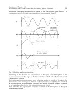
In Fig. 7 are presented the Nyquist plot for nominal value RC = 1 and the regions ABCD
(tetragon) and EFGH (rectangle) for two frequencies ω =0.2 and ω = 2.0. It gives us the
possibility to evaluate the envelope of Nyquist plot for these frequencies. It’s seen that
Kharitonov polynomials approach (rectangle) gives some overestimation compared with
linear interval equations method.
EXAMPLE 4. Consider a second-order low-pass Sallen - Key section of Fig.1
Let denote R
1
= 1/G
1
and R
2
= 1/G
2
.
We have now a transmittance of the form
1sC)RR(sCRCR
1
U
U
)s(K
221
2
2211
1
2
+++
==
.
Assuming R
1
C
1
= R
2
C
2
/2= RC = [1-ε, 1+ε], ε = 0.1, we have
[][]
1s3.3,7.2s42.2,62.1
1
U
U
)s(K
2
1
2
++
==
{
}
]42.2,62.1[xfor,x1)j(GRe
22
ωω=−∈ω
{
}
]3.3,7.2[xfor,x)j(GIm
ω
ω
=
=
ω
In Fig. 8a and 8b are drawn fragments of Nyquist plot for nominal value RC = 1.0 and
appropriate regions for ω = 0.2 and ω = 1.0.
Although uncertainties in the Example 4 are greater then in previous one both methods
produce smaller regions. There are two reasons of such results: Firstly, the different
coefficients of the transfer function are sometimes dependent; secondly, improved division
defined by (49) is not optimal whereas relation (50) leads to the optimal enclosure.
4. Conclusions
An efficient and well motivated approach to the problem linear analog circuit tolerance was
described. One-parameter tolerance problem was solved for bilinear and biquadratic
transfer function. This unified method was based on the range evaluation of a quotient of
two polynomials of second or fourth order. It was done by computing coefficients of
Bernstein polynomials generated for some Taylor expansion (form) of a rational function.
The Taylor forms together with Bernstein expansions constitute a significant enhancement
of the toolkit of interval analysis, see also (Neumaier, 2002).
Linear Analog Circuits Problems by Means of Interval Analysis Techniques
161
a)
0.5 0.6 0.7 0.8 0.9
-0.7
-0.6
-0.5
-0.4
-0.3
Imaginary Axis
ω
=0.2
Real Axis
b)
-0.2 -0.1 0 0.1 0.2
-0.5
-0.4
-0.3
-0.2
-0.1
ω
=1.0
Real Axis
Imaginary Axis
Fig. 8. Regions of uncertainty and Nyquist plot
Advances in Analog Circuits
162
The results presented in this chapter make it possible, by simple algorithms, to obtain the
Nyquist envelope (consequently the amplitude envelope and the phase envelope) of an
interval rational transfer function of a continuous-time system. It gives possibility to readily
check whether system with such uncertainty comply with frequency response specifications.
The results of the numerical calculations are quite satisfactory. It indicates that the interval
analysis seems to be a promising tool for robust analysis of linear systems. Numerical
studies show that it’s necessary next step to “more” optimal complex interval division
(Lohner & Wolff von Gudenberg, 1985; Moore et al., 2009).
5. References
Antreich, K.J.; Graeb, H.E., & Wieser, C.U. (1994). Circuit analysis and optimization driven
by worst-case distances,
IEEE Trans. Computer-Aided Design, Vol. 13, No. 1,
pp. 57-71, ISSN: 0278-0070.
Bartlett, A.C.; Tesi., A. & Vicino, A. (1993). Frequency response of uncertain systems with
interval plants”,
IEEE Trans. Automat. Contr., Vol. 38, No. 6, pp. 929-933,
ISSN: 1063-6536.
Chen, J J. & Hwang, C. (1998a). Computing frequency responses of uncertain systems”,
IEEE Trans. Circuits Syst. I, Vol. 45, No. 3, pp. 304-307, ISSN: 1057-7122.
Chen, J J. & Hwang, C. (1998b). Value sets of polynomial families with coefficients
depending nonlinearly on perturbed parameters,
IEE Proc. – Control Theory and
Applications,
vol. 145, No. 1, pp. 73-82, ISSN: 1751-8644.
Chen, W K. (2009).
The Circuits and Filters Handbook, CRC Press, ISBN: 9781420055276, 3rd
ed., Boca Raton, FL.
Dasgupta, S. (1988). Kharitonov’s theorem revisited,
Syst. Contr. Lett., Vol. 11, No. 5, 381-384,
ISSN:0167-691.
Elden, L. & Wittmeyer-Koch, L. (1990).
Numerical Analysis, Academic Press,
ISBN: 0-12-236430-9, Boston.
Femia, N. & Spagnuolo,G. (1999). Genetic optimization of interval arithmetic-based worst
case circuit tolerance analysis,
IEEE Trans. Circuits Syst. I, Vol. 46, No. 12,
pp.1441-56, ISSN: 1057-7122.
Garczarczyk, Z. (1993). An interval approach to finding all equilibrium points of some
nonlinear resistive circuits, In:
Circuit Theory and Design’93, Dedieu, H. (Ed.),
pp.1281-86, Elsevier, ISBN: 0-444-81664-X, Amsterdam.
Garczarczyk, Z. (1995) An efficient method for computing the range values of a rational
function with application,
Proceedings of the European Conference on Circuit Theory
and Design (ECCTD'95)
, pp. 459-462, ISBN: 975-561-061-8, Istanbul, 27-31 August,
1995, Istanbul Technical University, Istanbul, Turkey.
Garczarczyk, Z. (1999). Frequency responses of linear systems with interval parameters,
Proceedings of the ECCTD’99, pp.615-18, Stresa, Italy, 29 August - 2 September 1999,
Politecnico di Torino, Torino, Italy.
Garczarczyk, Z. (2002). Parallel schemes of computation for Bernstein coefficients and their
applications,
Proceedigs of the International Conference on Parallel Computing in
Electrical Engineering (PARELEC 2002),
pp. 334-337, ISBN: 0-7695-1730-7, Warsaw,
22-25 September, 2002, IEEE Computer Society, Los Alamitos, CA.
Linear Analog Circuits Problems by Means of Interval Analysis Techniques
163
Geher, K. (1971). Theory of Network Tolerances, Akademiai Kiado, Budapest.
Hwang, C. & Yang, S F. (2002). Generation of frequency-response templates for linear
systems with an uncertain time delay and multilinearly-correlated parameter
perturbation responses of uncertain systems,
IEEE Trans. Circuits Syst. I, Vol. 49,
No. 3, , pp. 378-383, ISSN: 1057-7122.
Kharitonov,V.L. (1979) Asymptotic stability of an equilibrium position of a family of
systems of linear differential equations,
Diff. Equations, Vol.14, No. 11, 1483-1485.
Kolev ,L.V.; V. Mladenov, V. & Vladov, S. (1988). Interval mathematics algorithms for
tolerance analysis,
IEEE Trans. Circuits Syst., Vol. 35, No. 8, pp.967-975,
ISSN: 0098-4094.
Lohner, L. & Wolff von Gudenberg, J. (1985). Complex interval division with maximal
accuracy, In:
Proceedings of 7th Symposium on Computer Arithmetic, Hwang, K. (Ed.),
pp. 332-336, 1985, IEEE Computer Society, Urbana, IL.
Moore, R.E.; Kearfott, R.B. & Cloud, M.J. (2009).
Introduction to Interval Analysis, SIAM Press,
ISBN: 978-0-898716-69-6, Philadephia, PA.
Nataraj, P.S.V. & Barve, J.J. (2003). Reliable computation of frequency response plots for
nonrational transfer functions to prescribed accuracy,
Reliable Computing, Vol. 9,
No.5, 373-389, ISSN: 1385-3139.
Neumaier, A. (1990).
Interval Methods for Systems of Equations, Cambridge University Press,
ISBN: 0-521-33196-X, Cambridge.
Neumaier, A. (2002). Taylor forms – use and limits,
HTML document,
Oettli W., Prager W., Compatibility of approximate solution of linear equations with given
error bounds for coefficients and right-hand sides,
Numer. Math., Vol. 6, No. 1, 1964,
pp.405-409, ISSN: 0029-599X .
Petkovic, M.S. & Petkovic, L.D. (1998).
Complex Interval Arithmetic ans Its Applications,
Wiley-VCH, ISBN: 3-527-40134-2, Berlin.
Ratschek, H. & Rokne, J. (1984).
Computer Methods for the Range of Functions, Ellis Horwood,
ISBN: 085312703, Chichester.
Rokne, J. & Lancaster, P. (1971). Complex interval arithmetic,
Comm. ACM., vol. 14,
pp. 111-112, ISSN:0001-0782.
Shi, C J.R. & Tian, M.W. (1999). Simulation and sensitivity of linear analog circuits under
parameter variations by robust interval analysis,
ACM Trans. Design Automat.
Electron. Syst.,
Vol. 4, No.3, pp.280-312, ISSN: 1084-4309.
Spence, R. & Soin, R.S. (1997).
Tolerance Design of Electronic Circuits, Imperial College Press,
ISBN: 1-86094-040-4, London.
Tan, N. & Atherton, D.P. (2000). Frequency response of uncertain systems: A 2q-convex
parpolygonal approach,
IEE Proc Control Theory Appl., Vol. 147, No. 9, pp. 547-555,
ISSN: 1350-2379.
Tan, N. (2002). Computing of the frequency response of multilinear affine systems,
IEEE
Trans. Automat. Contr.,
Vol. 47, No.10, pp. 1691-1696, ISSN: 1063-6536.
Tian, M.W. & Shi, C J.R. (2000). Worst case tolerance analysis of linear analog circuits using
sensitivity bands,
IEEE Trans. Circuits Syst. –I, Vol. 47, No. 8, pp.1138-1145,
ISSN: 1057-7122.