Ultra Wideband Communications Novel Trends System, Architecture and Implementation Part 2 doc
Bạn đang xem bản rút gọn của tài liệu. Xem và tải ngay bản đầy đủ của tài liệu tại đây (633.1 KB, 25 trang )
Measurements of the Nonlinearity of the Ultra Wideband Signals Transformation
15
This example illustrates special importance of linearity in UWB receivers. Besides, it is clear
that for UWB receivers testing one should use UWB signals. In nonlinear radars and
nonlinear reflectometers such measurements are necessary to observe the nonlinear
response of the object against the background of nonlinear distortions in the receiver
(E. Semyonov & A. Semyonov, 2007).
8. Conclusion
The considered method is effective for the following tasks.
1.
Investigation of devices (for example, receivers) for ultra wideband communication
systems (including design stage).
2.
Detection of imperfect contacts and other nonlinear elements in wire transmission lines.
3.
Remote and selective detection of substances with the use of their nonlinear properties.
The main advantages of the considered approach are listed below.
1.
Real signals transmitted in UWB systems can be used as test signals.
2.
Nonlinear signal distortions in the generator are acceptable.
3.
Measurement of distance from nonlinear discontinuity is possible.
4.
Nonlinear response is several times greater than the response to sinusoidal or two-
frequency signal.
The designed devices and measuring setups show high efficiency for frequency ranges with
various upper frequency limits (from 20 kHz to 20 GHz).
The developed virtual analyzers provide corresponding investigations of devices and
systems at design stage.
9. Acknowledgment
This study was supported by the Ministry of Education and Science of the Russian
Federation under the Federal Targeted Programme “Scientific and Scientific-Pedagogical
Personnel of the Innovative Russia in 2009-2013” (the state contracts no. P453 and no. P690)
and under the Decree of the Government of the Russian Federation no. 218 (the state
contract no. 13.G25.31.0017).
10. References
Arnstein, D. (1979). Power division in spread spectrum systems with limiting. IEEE
Transactions on Communications, Vol.27, No.3, (March 1979), pp. 574-582, ISSN: 0090-
6778
Arnstein, D.; Vuong, X.; Cotner, C. & Daryanani, H. (1992) The IM Microscope: A new
approach to nonlinear analysis of signals in satellite communications systems.
COMSAT Technical Review, Vol.22, No.1, (Spring 1992), pp. 93-123, ISSN 0095-9669
Bryant, P. (2007). Apparatus and method for locating nonlinear impairments in a
communication channel by use of nonlinear time domain reflectometry,
Descriptions of Invention to the Patent No. US 7230970 B1 of United States, 23.02.2011,
Available from:
Chen, S W.; Panton, W. & Gilmore, R. (1996). Effects of Nonlinear Distortion on CDMA
Communication Systems. IEEE Transactions on Microwave Theory and Techniques,
Vol.44, No.12, (December 1996), pp. 2743-2750, ISSN: 0018-9480
Ultra Wideband Communications: Novel Trends – System, Architecture and Implementation
16
Green, E. & Roy, S. (2003). System Architectures for High-rate Ultra-wideband
Communication Systems: A Review of Recent Developments, 22.02.2011, Available
from:
Lipshitz, S.; Vanderkooy, J. & Semyonov, E. (2002). Noise shaping in digital test-signal
generation, Preprints of AES 113
th
Convention, Preprint No.5664, Los Angeles,
California
, USA, October 5-8, 2002
Loschilov, A.; Semyonov E.; Maljutin N.; Bombizov A.; Pavlov A.; Bibikov T.; Iljin A.;
Gubkov A. & Maljutina A. (2009). Instrumentation for nonlinear distortion
measurements under wideband pulse probing, Proceedings of 19
th
International
Crimean
Conference “Microwave & Telecommunication Technology” (CriMiCo’2009),
pp. 754-755, ISBN:
978-1-4244-4796-1, Sevastopol, Crimea, Ukraine, September
14-18, 2009
Semyonov, E. (2002). Noise shaping for measuring digital sinusoidal signal with low total
harmonic distortion, Preprints of AES 112
th
Convention, Preprint No.5621, Munich,
Germany, May 10-13,
2002
Semyonov, E. (2004). Method for investigating non-linear properties of object, Descriptions of
Invention to the Patent No. RU 2227921 C1 of Russian Federation, 23.02.2011,
Available from:
from:
&KC=C1&FT=D&date=20040427&DB=EPODOC&locale=en_gb
Semyonov, E. (2005). Method for researching non-linear nature of transformation of signals
by object, Descriptions of Invention to the Patent No. RU 2263929 C1 of Russian
Federation, 23.02.2011, Available from:
biblio?CC=RU&NR=2263929C1&KC=C1&FT=D&date=20051110&DB=EPODOC&lo
cale=en_gb
Semyonov, E. & Semyonov, A. (2007). Applying the Difference between the Convolutions of
Test Signals and Object Responses to Investigate the Nonlinearity of the
Transformation of Ultrawideband Signals. Journal of Communications Technology and
Electronics, Vol.52, No.4, (April 2007), pp. 451-456, ISSN 1064-2269
Semyonov, E.; Maljutin, N. & Loschilov, A. (2009). Virtual nonlinear impulse network
analyzer for Microwave Office, Proceedings of 19
th
International Crimean Conference
“Microwave & Telecommunication Technology” (CriMiCo’2009), pp. 103-104, ISBN:
978-1-4244-4796-1, Sevastopol, Crimea, Ukraine, September 14-18, 2009
Sobhy, M.; Hosny, E.; Ng M. & Bakkar E. (1996). Non-Linear System and Subsystem
Modelling in The Time Domain. IEEE Transactions on Microwave Theory and
Techniques, Vol.44, No.12, (December 1996), pp. 2571-2579, ISSN: 0018-9480
Snezko, O. & Werner, T. (1997) Return Path Active Components Test Methods and
Performance Comparison, Proceedings of Conference on Emerging Technologies,
pp. 263-294, Nashville, Tennessee, USA, 1997
Verspecht, J. (1996). Black Box Modelling of Power Transistors in the Frequency Domain, In:
Conference paper presented at the INMMC '96, Duisburg, Germany, 22.02.2011,
Verspecht, J. & Root D. (2006). Polyharmonic Distortion Modeling. IEEE Microwave
Magazine, Vol.7, No.3, (June 2006), pp. 44-57, ISSN: 1527-3342
1. Introduction
Ultra-wideband (UWB) communication is a viable technology to provide high data rates
over broadband wireless channels for applications, including wireless multimedia, wireless
Internet access, and future-generation mobile communication systems (Karaoguz, 2001;
Stoica et al., 2005). Two of the most critical challenges in the implementation of UWB systems
are the timing acquisition and channel estimation. The difficulty in them arises from UWB
signals being the ultra short low-duty-cycle pulses operating at very low power density. The
Rake receiver (Turin, 1980) as a prevalent receiver structure for UWB systems utilizes the high
diversity in order to effectively capture signal energy spread over multiple paths and boost the
received signal-to-noise ratio (SNR). However, to perform maximal ratio combining (MRC),
the Rake receiver needs the timing information of the received signal and the knowledge of
the channel parameters, namely, gains and tap delays. Timing errors as small as fractions of
a nanosecond could seriously degrade the system performance (Lovelace & Townsend, 2002;
Tian & Giannakis, 2005). Thus, accurate timing acquisition and channel estimation is very
essentially for UWB systems.
Many research efforts have been devoted to the timing acquisition and channel estimation of
UWB signals. However, most reported methods suffer from the restrictive assumptions, such
as, demanding a high sampling rates, a set of high precision time-delay systems or invoking
a line search, which severally limits their usages. In this chapter, we are focusing on the low
sampling rate time acquisition schemes and channel estimation algorithms of UWB signals.
First, we develop a novel optimum data-aided (DA) timing offset estimator that utilizes only
symbol-rate samples to achieve the channel delay spread scale timing acquisition. For this
purpose, we exploit the statistical properties of the power delay profile of the received signals
to design a set of the templates to ensure the effective multipath energy capture at any time.
Second, we propose a novel optimum data-aided channel estimation scheme that only relies
on frame-level sampling rate data to derive channel parameter estimates from the received
waveform. The simulations are provided to demonstrate the effectiveness of the proposed
approach.
Low Sampling Rate Time Acquisition Schemes
and Channel Estimation Algorithms of
Ultra-Wideband Signals
Wei Xu and Jiaxiang Zhao
Nankai University
China
2
2 Will-be-set-by-IN-TECH
2. The channel model
From the channel model described in (Foerster, 2003), the impulse response of the channel is
h
(t)=X
N
∑
n=1
K
(n )
∑
k=1
α
nk
δ(t − T
n
−τ
nk
) (1)
where X is the log-normal shadowing effect. N and K
(n) represent the total number of the
clusters, and the number of the rays in the nth cluster, respectively. T
n
is the time delay of
the nth cluster relative to a reference at the receiver, and τ
nk
is the delay of the kth multipath
component in the nth cluster relative to T
n
. From (Foerster, 2003), the multipath channel
coefficient α
nk
can be expressed as α
nk
= p
nk
β
nk
where p
nk
assumes either +1or−1with
equal probability, and β
nk
> 0 has log-normal distribution.
The power delay profile (the mean square values of
{β
2
nk
}) is exponential decay with respect
to
{T
n
} and {τ
nk
}, i.e.,
β
2
nk
= β
2
00
exp( −
T
n
Γ
) exp(−
τ
nk
γ
) (2)
where
β
2
00
is the average power gain of the first multipath in the first cluster. Γ and γ are
power-delay time constants for the clusters and the rays, respectively.
The model (1) is employed to generate the impulse responses of the propagation channels in
our simulation. For simplicity, an equivalent representation of (1) is
h
(t)=
L−1
∑
l=0
α
l
δ(t − τ
l
) (3)
where L represents the total number of the multipaths, α
l
includes log-normal shadowing
and multipath channel coefficients, and τ
l
denotes the delay of the l th multipath relative to
the reference at the receiver. Without loss of generality, we assume τ
0
< τ
1
< ···< τ
L−1
.
Moreover, the channel only allows to change from burst to burst but remains invariant (i.e.,
{α
l
, τ
l
}
L−1
l
=0
are constants) over one transmission burst.
3. Low sampling rate time acquisition schemes
One of the most acute challenges in realizing the potentials of the UWB systems is to develop
the time acquisition scheme which relies only on symbol-rate samples. Such a low sampling
rate time acquisition scheme can greatly lower the implementation complexity. In addition,
the difficulty in UWB synchronization also arises from UWB signals being the ultrashort
low-duty-cycle pulses operating at very low power density. Timing errors as small as fractions
of a nanosecond could seriously degrade the system performance (Lovelace & Townsend,
2002; Tian & Giannakis, 2005).
A number of timing algorithms are reported for UWB systems recently. Some of the
timing algorithms(Tian & Giannakis, 2005; Yang & Giannakis, 2005; Carbonelli & Mengali,
2006; He & Tepedelenlioglui, 2008) involve the sliding correlation that usually used in
traditional narrowband systems. However, these approaches inevitably require a searching
procedure and are inherently time-consuming. Too long synchronization time will affect
18
Ultra Wideband Communications: Novel Trends – System, Architecture and Implementation
Low Sampling Rate Time Acquisition Schemes and Channel Estimation Algorithms of Ultra-wideband Signals 3
symbol detection. Furthermore, implementation of such techniques demands very fast
and expensive A/D converters and therefore will result in high power consumption.
Another approach (Carbonelli & Mengali, 2005; Furusawa et al., 2008; Cheng & Guan, 2008;
Sasaki et al., 2010) is to synchronize UWB signals through the energy detector. The merits
of using energy detectors are that the design of timing acquisition scheme could benefit
from the statistical properties of the power delay profile of the received signals. Unlike
the received UWB waveforms which is unknown to receivers due to the pulse distortions,
the statistical properties of the power delay profile are invariant. Furthermore, as shown
in (Carbonelli & Mengali, 2005), an energy collection based receiver can produce a low
complexity, low cost and low power consumption solution at the cost of reduced channel
spectral efficiency.
In this section, a novel optimum data-aided timing offset estimator that only relies on
symbol-rate samples for frame-level timing acquisition is derived. For this purpose, we
exploit the statistical properties of the power delay profile of the received signals to design
a set of the templates to ensure the effective multipath energy capture at any time. We show
that the frame-level timing offset acquisition can be transformed into an equivalent amplitude
estimation problem. Thus, utilizing the symbol-rate samples extracted by our templates and
the ML principle, we obtain channel-dependent amplitude estimates and optimum timing
offset estimates.
3.1 The signal model
During the acquisition stage, a training sequence is transmitted. Each UWB symbol
is transmitted over a time-interval of T
s
seconds that is subdivided into N
f
equal size
frame-intervals of length T
f
. A single frame contains exactly one data modulated ultrashort
pulse p
(t) of duration T
p
. And the transmitted waveform during the acquisition has the form
as
s
(t)=
E
f
NN
f
−1
∑
j=0
d
[j]
N
ds
p(t − jT
f
− a
j
N
f
) (4)
where
{d
l
}
N
ds
−1
l
=0
with d
l
∈{±1} is the DS sequence. The time shift is chosen to be T
h
/2
with T
h
being the delay spread of the channel. The assumption that there is no inter-frame
interference suggests T
h
≤ T
f
. For the simplicity, we assume T
h
= T
f
and derive the
acquisition algorithm. Our scheme can easily be extended to the case where T
f
≥ T
h
.The
training sequence
{a
n
}
N−1
n
=0
is designed as
{0, 0, 0, ···0
n=0,1,···,N
0
−1
1, 0, 1, 0, ···1, 0
n=N
0
,N
0
+1,···,N−1
},(5)
i.e., the first N
0
consecutive symbols are chosen to be 0 , and the rest symbols alternately switch
between 1 and 0 .
The transmitted signal propagates through an L-path fading channel as shown in (3). Using
the first arriving time τ
0
, we define the relative time delay of each multipath as τ
l,0
= τ
l
−τ
0
19
Low Sampling Rate Time Acquisition Schemes
and Channel Estimation Algorithms of Ultra-Wideband Signals
4 Will-be-set-by-IN-TECH
( )²
r(t)
W
2
(t)
W
0
(t)
Y
0
[n]
Y
2
[n]
W
1
(t)
Y
1
[n]
(n+1)Ts
nTs
(n+1)Ts
nTs
(n+1)Ts+T
d
nTs+T
d
(n+1)Ts
Fig. 1. The block diagram of acquisition approach.
for 1
≤l ≤L − 1 . Thus the received signal is
r
(t)=
E
f
NN
f
−1
∑
j=0
d
[j]
N
ds
p
R
(t−jT
f
−a
j
N
f
Δ−τ
0
)+n(t) (6)
where n
(t) is the zero-mean additive white Gaussian noise (AWGN) with double-side power
spectral density σ
2
n
/2 and p
R
(t)=
∑
L−1
l
=0
α
l
p(t −τ
l,0
) represents the convolution of the channel
impulse response (3) with the transmitted pulse p
(t) .
The timing information of the received signal is contained in the delay τ
0
which can be
decomposed as
τ
0
= n
s
T
s
+ n
f
T
f
+ ξ (7)
with n
s
=
τ
0
T
s
, n
f
=
τ
0
−n
s
T
s
T
f
and ξ ∈ [0,T
f
) .
In the next section, we present an DA timing acquisition scheme based on the following
assumptions: 1
)
There is no interframe interference, i.e., τ
L−1,0
≤ T
f
.2
)
The channel is
assumed to be quasi-static, i.e., the channel is constant over a block duration. 3
)
Since the
symbol-level timing offset n
s
can be estimated from the symbol-rate samples through the
traditional estimation approach, we assumed n
s
= 0 . In this chapter, we focus on acquiring
timing with frame-level resolution, which relies on only symbol-rate samples.
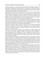
3.2 Analysis of symbol-rate sampled data Y
0
[n]
As shown in Fig. 1, the received signal (6) first passes through a square-law detector. Then,
the resultant output is separately correlated with the pre-devised templates W
0
(t), W
1
(t) and
W
2
(t) ,andsampledatnT
s
which yields {Y
0
[n]}
N−1
n
=1
,{Y
1
[n]}
N−1
n
=1
and {Y
2
[n]}
N−1
n
=1
. Utilizing
these samples, we derive an optimal timing offset estimator
ˆ
n
f
.
In view of (6), the output of the square-law detector is
R
(t)=r
2
(t)=(r
s
(t)+n(t))
2
= r
2
s
(t)+m(t)
=
E
f
NN
f
−1
∑
j=0
p
2
R
(t − jT
f
− a
j
N
f
−τ
0
)+m(t) (8)
20
Ultra Wideband Communications: Novel Trends – System, Architecture and Implementation
Low Sampling Rate Time Acquisition Schemes and Channel Estimation Algorithms of Ultra-wideband Signals 5
where m(t)=2r
s
(t)n(t)+n
2
(t) . When the template W(t) is employed, the symbol rate
sampled data Y
[n] is
Y
[n]=
T
s
0
R(t + nT
s
)W(t)dt .(9)
Now we derive the decomposition of Y
0
[n] , i.e., the symbol-rate samples when the template
W
0
(t) defined as
W
0
(t)=
N
f
−1
∑
k=0
w(t − kT
f
) , w(t)=
⎧
⎪
⎨
⎪
⎩
1, 0
≤ t <
T
f
2
−1,
T
f
2
≤ t < T
f
0, others
(10)
is employed. Substituting W
0
(t) for W(t) in (9), we obtain symbol-rate sampled data Y
0
[n] .
Recalling (5), we can derive the following proposition of Y
0
[n] .
Proposition 1: 1
)
For 1≤n < N
0
, Y
0
[n] can be expressed as
Y
0
[n]=N
f
I
ξ,0
+ M
0
[n] , (11)
2
)
For N
0
≤ n ≤ N −1, Y
0
[n] can be represented as
Y
0
[n]=
⎧
⎪
⎨
⎪
⎩
(2Ψ−N
f
)I
ξ,a
n−1
+M
0
[n] , ξ ∈ [0, T
η
)
(
2Ψ−N
f
+1)I
ξ,a
n−1
+M
0
[n] , ξ ∈ [T
η
, T
η
+
T
f
2
)
(
2Ψ−N
f
+2)I
ξ,a
n−1
+M
0
[n] , ξ ∈ [T
η
+
T
f
2
, T
f
)
(12)
where Ψ
n
f
−
1
2
, ∈ [−
1
2
,
1
2
] and T
η
∈ [
T
f
4
,
T
f
2
] . M
0
[n] is the sampled noise, and I
ξ,a
n
is
defined as
I
ξ,a
n
E
f
T
f
0
2
∑
m=0
p
2
R
(t + mT
f
− a
n
−ξ)w(t)dt . (13)
We prove the Proposition 1 and the fact that the sampled noise M
0
[n] can be approximated by
a zero mean Gaussian variable in (Xu et al., 2009) in Appendix A and Appendix B respectively.
There are some remarks on the Proposition 1:
1
)
The fact of a
n−1
∈{0, 1} suggests that I
ξ,a
n−1
in (12) is equal to either I
ξ,0
or I
ξ,1
.
Furthermore, I
ξ,0
and I
ξ,1
satisfy I
ξ,1
= −I
ξ,0
whose proof is contained in Fact 1 of Appendix I.
2
)
Equation (12) suggests that the decomposition of Y
0
[n] varies when ξ falls in different
subintervals, so correctly estimating n
f
need to determine to which region ξ belongs.
3
)
Fact 2 of Appendix A which states
I
ξ,0
> 0, ξ ∈ [0, T
η
)
[T
η
+
T
f
2
, T
f
]
I
ξ,0
< 0, ξ ∈ [T
η
, T
η
+
T
f
2
)
(14)
suggests that it is possible to utilize the sign of I
ξ,0
to determine to which subinterval ξ
belongs. However, when I
ξ,0
> 0, ξ could belong to either [0, T
η
) or [T
η
+
T
f
2
, T
f
) .Toresolve
this difficulty, we introduce the second template W
1
(t) in the next section.
21
Low Sampling Rate Time Acquisition Schemes
and Channel Estimation Algorithms of Ultra-Wideband Signals
6 Will-be-set-by-IN-TECH
3.3 Analysis of symbol-rate sampled data Y
1
[n]
The symbol-rate sampled data Y
1
[n] is obtained when the template W
1
(t) is employed. W
1
(t)
is a delayed version of W
0
(t) with the delayed time T
d
where T
d
∈ [0,
T
f
2
] . Our simulations
show that we obtain the similar performance for the different choices of T
d
. For the simplicity,
we choose T
d
=
T
f
4
for the derivation. Thus, we have
Y
1
[n]=
T
s
+
T
f
4
T
f
4
R(t + nT
s
)W
0
(t −
T
f
4
)dt
=
T
s
0
R(t + nT
s
+
T
f
4
)W
0
(t)dt . (15)
Then we can derive the following proposition of Y
1
[n] .
Proposition 2: 1
)
For 1≤n<N
0
, Y
1
[n] can be expressed as
Y
1
[n]=N
f
J
ξ,0
+ M
0
[n] . (16)
2
)
For N
0
≤ n ≤ N −1, Y
1
[n] can be decomposed as
Y
1
[n]=
⎧
⎪
⎨
⎪
⎩
(2Ψ−N
f
−1)J
ξ,a
n−1
+M
1
[n] , ξ ∈[0, T
η
−
T
f
4
)
(
2Ψ−N
f
)J
ξ,a
n−1
+M
1
[n] , ξ ∈[T
η
−
T
f
4
, T
η
+
T
f
4
)
(
2Ψ−N
f
+1)J
ξ,a
n−1
+M
1
[n] , ξ ∈[T
η
+
T
f
4
, T
f
)
(17)
where J
ξ,0
satisfies
J
ξ,0
< 0, ξ ∈ [0, T
η
−
T
f
4
)
[T
η
+
T
f
4
, T
f
)
J
ξ,0
> 0, ξ ∈ [T
η
−
T
f
4
, T
η
+
T
f
4
) .
(18)
Equation (14) and (18) suggest that the signs of I
ξ,0
and J
ξ,0
can be utilized jointly to determine
the range of ξ , which is summarized as follows:
Proposition 3: ξ
∈ [0, T
f
] defined in (7) satisfies
1. If I
ξ,0
> 0andJ
ξ,0
> 0, then ξ ∈ ( T
η
−
T
f
4
, T
η
) .
2. If I
ξ,0
< 0andJ
ξ,0
> 0, then ξ ∈ ( T
η
, T
η
+
T
f
4
) .
3. If I
ξ,0
< 0andJ
ξ,0
< 0, then ξ ∈ ( T
η
+
T
f
4
, T
η
+
T
f
2
) .
4. If I
ξ,0
> 0andJ
ξ,0
< 0, then ξ ∈(0, T
η
−
T
f
4
) ∪ (T
η
+
T
f
2
, T
f
) .
The last case of Proposition 3 suggests that using the signs of I
ξ,0
and J
ξ,0
is not enough to
determine whether we have ξ
∈ ( 0,T
η
−
T
f
4
) or ξ ∈ ( T
η
+
T
f
2
, T
f
) . To resolve this difficulty,
the third template W
2
(t) is introduced. W
2
(t) is an auxiliary template and is defined as
W
2
(t)=
N
f
−1
∑
k=0
v(t−kT
f
), v(t)=
⎧
⎨
⎩
1, T
f
−2T
υ
≤t < T
f
−T
υ
−1, T
f
−T
υ
≤t < T
f
0, others
(19)
where T
υ
∈ (0, T
f
/10] . Similar to the proof of (14), we can prove that in this case, either
K
ξ,0
> 0for0< ξ < T
η
−
T
f
4
or K
ξ,0
< 0forT
η
+
T
f
4
< ξ < T
f
is valid, which yields the
information to determine which region ξ belongs to.
22
Ultra Wideband Communications: Novel Trends – System, Architecture and Implementation
Low Sampling Rate Time Acquisition Schemes and Channel Estimation Algorithms of Ultra-wideband Signals 7
3.4 The computation of the optimal timing offset estimator
ˆ
n
f
To seek the estimate of n
f
, we first compute the optimal estimates of I
ξ,0
and J
ξ,0
using (11) and
(16). Then, we use the estimate
ˆ
I
ξ,0
,
ˆ
J
ξ,0
and Proposition 3 to determine the region to which
ξ belongs. The estimate
ˆ
Ψ therefore can be derived using the proper decompositions of (12)
and (17). Finally, recalling the definition in (12) Ψ
= n
f
−
2
with ∈[−
1
2
,
1
2
] , we obtain
ˆ
n
f
=[
ˆ
Ψ
] ,
where
[·] stands for the round operation.
According to the signs of
ˆ
I
ξ,0
and
ˆ
J
ξ,0
, we summarize the ML estimate
ˆ
Ψ as follow:
Proposition 4:
• When
ˆ
I
ξ,0
> 0and
ˆ
J
ξ,0
> 0,
ˆ
Ψ =
1
A
N
−1
∑
n=N
0
[Z
n
+N
f
(I
2
ξ,0
+J
2
ξ,0
)] .
• When
ˆ
I
ξ,0
<0and
ˆ
J
ξ,0
>0,
ˆ
Ψ =
1
A
N
−1
∑
n=N
0
[Z
n
+( N
f
−1)I
2
ξ,0
+N
f
J
2
ξ,0
] .
• When
ˆ
I
ξ,0
<0and
ˆ
J
ξ,0
<0,
ˆ
Ψ =
1
A
N
−1
∑
n=N
0
[Z
n
+(N
f
−1)(I
2
ξ,0
+J
2
ξ,0
)] .
• When
ˆ
I
ξ,0
> 0and
ˆ
J
ξ,0
< 0,
ˆ
Ψ
=
⎧
⎪
⎪
⎪
⎨
⎪
⎪
⎪
⎩
1
A
N
−1
∑
n=N
0
[Z
n
+N
f
I
2
ξ,0
+(N
f
+1)J
2
ξ,0
] ,
ˆ
K
ξ,0
> 0
1
A
N
−1
∑
n=N
0
[Z
n
+(N
f
−2)I
2
ξ,0
+(N
f
−1)J
2
ξ,0
] ,
ˆ
K
ξ,0
< 0
where A
2(N −N
0
)(I
2
ξ,0
+ J
2
ξ,0
) and Z
n
Y
0
[n]I
ξ,a
n−1
+ Y
1
[n]J
ξ,a
n−1
. The procedures of
computing the optimal ML estimate
ˆ
Ψ in Proposition 4 are identical. Therefore, we only
present the computation steps when
ˆ
I
ξ,0
> 0and
ˆ
J
ξ,0
> 0.
1
)
Utilizing (11) and (16), we obtain the ML estimates
ˆ
I
ξ,0
=
1
(N
0
−1)N
f
N
0
−1
∑
n=1
Y
0
[n] ,
ˆ
J
ξ,0
=
1
(N
0
−1)N
f
N
0
−1
∑
n=1
Y
1
[n] . (20)
2
)
From 1
)
of Proposition 3, it follows T
η
−
T
f
4
< ξ < T
η
when
ˆ
I
ξ,0
> 0and
ˆ
J
ξ,0
> 0.
3
)
According to the region of ξ, we can select the right equations from (12) and (17) as
Y
0
[n]=(2Ψ − N
f
)I
ξ,a
n−1
+ M
0
[n] (21)
Y
1
[n]=(2Ψ − N
f
)J
ξ,a
n−1
+ M
1
[n] . (22)
Thus the log-likelihood function ln p
(y ; Ψ, I
ξ,a
n−1
, J
ξ,a
n−1
) is
N−1
∑
n=N
0
[Y
0
[n]−(2Ψ−N
f
)I
ξ,a
n−1
]
2
+[Y
1
[n]−(2Ψ−N
f
)J
ξ,a
n−1
]
2
.
It follows the ML estimate
ˆ
Ψ
=
1
A
∑
N−1
n
=N
0
[Z
n
+N
f
(I
2
ξ,0
+J
2
ξ,0
)] .
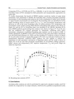
3.5 Simulation
In this section, computer simulations are performed. We use the second-order derivative of
the Gaussian pulse to represent the UWB pulse. The propagation channels are generated
23
Low Sampling Rate Time Acquisition Schemes
and Channel Estimation Algorithms of Ultra-Wideband Signals
8 Will-be-set-by-IN-TECH
0 5 10 15 20 25 30 35 40
10
−7
10
−6
10
−5
10
−4
10
−3
10
−2
10
−1
symbol SNR(dB) at the transmitter
MSE
N=12, multi−templates
N=30, multi−templates
N=12, noisy template
N=30, noisy template
Fig. 2. MSE performance under CM2 with d =4m
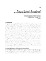
0 5 10 15 20 25
10
−6
10
−5
10
−4
10
−3
10
−2
10
−1
10
0
symbol SNR(dB) at the transmitter
BER
Perfect Timing
no Timing
N=12, multi−templates
N=30, multi−templates
N=12, noisy template
N=30, noisy template
Fig. 3. BER performance under CM2 with d= 4m
by the channel model CM2 described in (Foerster, 2003) . Other parameters are selected as
follows: T
p
= 1ns, N
f
= 25, T
f
= 100ns, T
υ
= T
f
/10 and the transmitted distance d = 4m .
In all the simulations, we assume that n
f
and ξ are uniformly distributed over [ 0, N
f
− 1]
and [0, T
f
] respectively. To evaluate the effect of the estimate
ˆ
n
f
on the bit-error-rates (BERs)
performance, we assume there is an optimal channel estimator at the receiver to obtain the
perfect template for tracking and coherent demodulation. The signal-to-noise ratios (SNRs)
24
Ultra Wideband Communications: Novel Trends – System, Architecture and Implementation
Low Sampling Rate Time Acquisition Schemes and Channel Estimation Algorithms of Ultra-wideband Signals 9
in all figures are computed through E
s
/σ
2
n
where E
s
is the energy spread over each symbol at
the transmitter and σ
2
n
is the power spectral density of the noise.
In Fig. 2 present the normalized mean-square error (MSE:E
{|(
ˆ
n
f
−n
f
)/N
f
|
2
})oftheproposed
algorithm in contrast to the approach using noisy template proposed in (Tian & Giannakis,
2005) . The figure shows that the proposed algorithm (blue curve) outperforms that
in (Tian & Giannakis, 2005) (red curve) when the SNR is larger than 10dB. For both algorithms,
the acquisition performance improves with an increase in the length of training symbols N ,
as illustrated by the performance gap among N
= 12 and N = 30. Fig. 3 illustrates the BER
performance for the both algorithms. The BERs corresponding to perfect timing (green curve)
and no timing (Magenta curve) are also plotted for comparisons.
4. Low sampling rate channel estimation algorithms
The channel estimation of UWB systems is essential to effectively capture signal energy spread
over multiple paths and boost the received signal-to-noise ratio (SNR). The low sampling
rate channel estimation algorithms have the merits that can greatly lower the implementation
complexity and reduce the costs. However, the development of low sampling rate channel
estimation algorithms is extremely challenging. This is primarily due to the facts that the
propagation models of UWB signals are frequency selective and far more complex than
traditional radio transmission channels.
Classical approaches to this problem are using the maximum likelihood (ML) method or
approximating the solutions of the ML problem. The main drawback of these approaches
is that the computational complexity could be prohibitive since the number of parameters to
be estimated in a realistic UWB channel is very high (Lottici et al., 2002). Other approaches
reported are the minimum mean-squared error schemes which have the reduced complexity
at the cost of performance (Yang & Giannakis, 2004). Furthermore, sampling rate of the
received UWB signal is not feasible with state-of-the-art analog-to-digital converters (ADC)
technology. Since UWB channels exhibit clusters (Cramer et al., 2002), a cluster-based channel
estimation method is proposed in (Carbonelli & Mitra, 2007). Different methods such as
subspace approach (Xu & Liu, 2003), first-order cyclostationary-based method (Wang & Yang,
2004) and compressed sensing based method (Paredes et al., 2007; Shi et al., 2010) proposed
for UWB channel estimation are too complex to be implemented in actual systems.
In this section, we develop a novel optimum data-aided channel estimation scheme that
only relies on frame-level sampling rate data to derive channel parameter estimates from the
received waveform. To begin with, we introduce a set of especially devised templates for
the channel estimation. The received signal is separately correlated with these pre-devised
templates and sampled at frame-level rate. We show that each frame-level rate sample of
any given template can be decomposed to a sum of a frequency-domain channel parameter
and a noise sample. The computation of time-domain channel parameter estimates proceeds
through the following two steps: In step one, for each fixed template, we utilize the samples
gathered at this template and the maximum likelihood criterion to compute the ML estimates
of the frequency-domain channel parameters of these samples. In step two, utilizing the
computed frequency-domain channel parameters, we can compute the time-domain channel
parameters via inverse fast transform (IFFT). As demonstrated in the simulation example,
25
Low Sampling Rate Time Acquisition Schemes
and Channel Estimation Algorithms of Ultra-Wideband Signals
10 Will-be-set-by-IN-TECH
Integrator
nT
m
W
i
(t)
Integrator
nT
m
W
0
(t)
Y
0
[n]
Y
i
[n]
Integrator
nT
m
W
S
(t)
Y
S
[n]
r(t)
.
.
.
.
.
.
Fig. 4. The block diagram of channel estimation scheme.
when the training time is fixed, more templates used for the channel estimation yield the
better (BER) performance.
4.1 The signal model
During the channel estimation process, a training sequence is transmitted. Each UWB
symbol is transmitted over a time-interval of T
s
seconds that is subdivided into N
f
equal size
frame-intervals of length T
f
, i.e., T
s
= N
f
T
f
. A frame is divided into N
c
chips with each of
duration T
c
, i.e., T
f
= N
c
T
c
. A single frame contains exactly one data modulated ultrashort
pulse p
(t) (so-called monocycle) of duration T
p
which satisfies T
p
≤ T
c
.Thepulsep(t)
normalized to satisfy
p(t)
2
dt = 1 can be Gaussian, Rayleigh or other. Then the waveform
for the training sequence can be written as
s
(t)=
E
f
N
s
−1
∑
n=0
N
f
−1
∑
j=0
b
n
p(t − nT
s
− jT
f
) (23)
where E
f
represents the energy spread over one frame and N
s
is the length of the training
sequence; b
n
denotes data, which is equal to 1 during training phase.
Our goal is to derive the estimate of the channel parameter sequence h
=[h
0
, h
1
, ···, h
L−1
] .
Since from the assumption L is unknown, we define a N
c
-length sequence p as
p
=[h
0
, h
1
, ···, h
L−1
, h
L
, h
L+1
, ···, h
N
c
−1
] (24)
where h
l
= 0forl ≥ L . The transmitted signal propagates through an L-path fading channel
as shown in (3). Thus the received signal is
r
(t)=
E
f
N
s
−1
∑
n=0
N
f
−1
∑
j=0
N
c
−1
∑
l=0
h
l
p(t −nT
s
− jT
f
−lT
c
)+n(t) (25)
where n
(t) is the zero-mean additive white Gaussian noise (AWGN) with double-side power
spectral density σ
2
n
/2 .
26
Ultra Wideband Communications: Novel Trends – System, Architecture and Implementation
Low Sampling Rate Time Acquisition Schemes and Channel Estimation Algorithms of Ultra-wideband Signals 11
4.2 The choices of templates
In this section, a novel channel estimation method that relies on symbal-level samples is
derived. As shown in Fig. 4, the received signal (25) is separately correlated with the
pre-devised templates W
0
(t), W
1
(t), ···, W
S
(t),andsampledatnT
m
where sampling period
T
m
is on the order of T
f
.LetY
i
[n] denote the n-th sample corresponding to the template W
i
(t) ,
that is,
Y
i
[n]=
T
m
0
r(t + nT
m
)W
i
(t)dt (26)
with i
= 0, 1, ···, S . Utilizing these samples, we derive the ML estimate of the channel
parameter sequence p in (24).
First we introduce a set of S
+ 1 templates used for the channel estimation. The number S is
chosen as a positive integer factor of N
c
/2 by assuming that N
c
which represents the number
of chips T
c
in each frame is an even number. That is, we have N
c
= 2SM with M also being
defined as a positive integer factor of N
c
/2 . The i-th template is defined as
W
i
(t)=
E
f
N
o
−1
∑
k=0
ω
ik
N
o
[
p(t −kT
c
)+p (t − T
f
−kT
c
)
]
(27)
with N
o
= 2S = N
c
/M , ω
ik
N
o
= e
−j
2πik
N
o
and i ∈{0, 1, ···, S}. The duration of each template
W
i
(t) is equal to the sampling period T
m
which can be expressed as
T
m
=(N
c
+ N
o
)T
c
= T
f
+ N
o
T
c
. (28)
4.3 The computation of the channel parameter sequence p
In this section, we derive the channel estimation scheme that only relies on frame-level
sampling rate data. To begin with, let us introduce some notations. Recalling the equation
N
o
= N
c
/M following (27), we divide the N
c
-length sequence p into M blocks each of size
N
o
. Therefore, equation (24) becomes
p
=[h
0
, h
1
, ···, h
m
, ···, h
M −1
] (29)
where the m-th block h
m
is defined as
h
m
=[h
mN
o
h
mN
o
+1
··· h
mN
o
+N
o
−1
] (30)
with m
∈{0, 1, ···, M−1}.LetF
i
denote the N
o
-length coefficient sequence of the i-th
template W
i
(t) in (27), i.e.,
F
i
=[ω
0
N
o
ω
i
N
o
ω
2i
N
o
··· ω
(N
o
−1)i
N
o
] . (31)
The discrete Fourier transform (DFT) of the N
o
-length sequence h
m
=
[
h
mN
o
h
mN
o
+1
··· h
mN
o
+N
o
−1
] is denoted as
H
m
=[H
0
m
, H
1
m
, ···, H
i
m
, ···, H
N
o
−1
m
] (32)
27
Low Sampling Rate Time Acquisition Schemes
and Channel Estimation Algorithms of Ultra-Wideband Signals
12 Will-be-set-by-IN-TECH
where the frequency-domain channel parameter H
i
m
is
H
i
m
= F
i
h
T
m
=
N
o
−1
∑
k=0
ω
ik
N
o
h
mN
o
+k
(33)
with m
∈{0, 1, ···, M −1} and i ∈{0, 1, ···, S}.
Our channel estimation algorithm proceeds through the following two steps.
Step 1: Utilizing the set of frame-level samples
{Y
i
[n]}
N
n
=1
generated from the i-th template,
we compute the ML estimates of the frequency-domain channel parameters
{H
i
m
}
M
m
=1
for
i
∈{0, 1, ···, S}. To do this, we show that the samples {Y
i
[n]}
N−1
n
=0
from the i-th template has
the following decomposition.
Proposition 1: Every sample in the set
{Y
i
[n]}
N−1
n
=0
can be decomposed into the sum of a
frequency-domain channel parameter and a noise sample, that is,
⎧
⎪
⎪
⎪
⎪
⎪
⎪
⎪
⎪
⎪
⎨
⎪
⎪
⎪
⎪
⎪
⎪
⎪
⎪
⎪
⎩
Y
i
[qM]=2E
f
H
i
0
+ Z
i
[qM]
Y
i
[qM + 1]=2E
f
H
i
1
+ Z
i
[qM + 1]
.
.
.
Y
i
[qM + m]=2E
f
H
i
m
+ Z
i
[qM + m]
.
.
.
Y
i
[qM + M −1]=2E
f
H
i
M
−1
+ Z
i
[qM + M − 1]
(34)
where Z
i
[n] represents the noise sample. The parameter q belongs to the set {0, 1, ···, Q −1}
with Q =
N
M
.
Performing ML estimation to the
(m + 1)-th equation in (34) for q = 0, 1, ···, Q − 1, we can
compute the ML estimate
ˆ
H
i
m
for the frequency-domain channel parameter H
i
m
as
ˆ
H
i
m
=
1
2E
f
Q
Q−1
∑
q =0
Y
i
[qM + m] (35)
with m
∈{0, 1, ···, M −1} and i ∈{0, 1, ···, S}.
Step 2: Utilizing the computed frequency-domain channel parameters
{
ˆ
H
i
m
}
S
i
=0
from the
Step 1, we derive the estimate of the time-domain channel sequence h
m
for m ∈{0, 1, ···, M −
1}. From the symmetry of the DFT, the time-domain channel parameter sequence h
m
=
[
h
mN
o
h
mN
o
+1
··· h
mN
o
+N
o
−1
] is a real valued sequence, which suggests that the DFT of h
m
satisfies
H
N
o
−i
m
=(H
i
m
)
∗
(36)
with i
∈{0, 1, ···, S} and S = N
o
/2 .
Utilizing equation (36), we obtain the estimate for the N
o
-point DFT of h
m
as
ˆ
H
m
=[
ˆ
H
0
m
,
ˆ
H
1
m
, ···,
ˆ
H
S
m
, (
ˆ
H
S−1
m
)
∗
, ···, (
ˆ
H
2
m
)
∗
, (
ˆ
H
1
m
)
∗
] (37)
28
Ultra Wideband Communications: Novel Trends – System, Architecture and Implementation
Low Sampling Rate Time Acquisition Schemes and Channel Estimation Algorithms of Ultra-wideband Signals 13
The estimate of the time-domain channel parameter
ˆ
h
m
can be compute via N
o
-point IFFT. In
view of equation (29), the estimated channel parameter sequence p in (24) is given by
ˆp
=[
ˆ
h
0
,
ˆ
h
1
, ···,
ˆ
h
M −1
] . (38)
−6 −4 −2 0 2 4 6 8 10 12
10
−3
10
−2
10
−1
10
0
10
1
symbol SNR(dB) at the transmitter
MSE
Algorithm in (Wang & Ge; 2007) with Ns=30
S=4, Ns=30
S=8, Ns=30
S=16, Ns=30
Fig. 5. MSE performance of the algorithm proposed in (Wang & Ge, 2007) and the proposed
algorithm with different number of templates (S
= 4 , 8 ,16), when the length of the training
sequence N
s
is 30 .
4.4 Simulation
In this section, computer simulations are performed to test the proposed algorithm. The
propagation channels are generated by the channel model CM 4 described in (Foerster, 2003) .
We choose the second-order derivative of the Gaussian pulse as the transmitted pulse with
duration T
p
= 1ns. Other parameters are selected as follows: T
f
= 64ns, T
c
= 1ns, N
c
= 64
and N
f
= 24 .
Fig. 5 presents the normalized mean-square error (MSE) of our channel estimation algorithm
with different number of templates (S
= 4 , 8 , 16) when the length of the training sequence
N
s
is 30 . As a comparison, we also plot the MSE curve of the approach in (Wang & Ge, 2007)
which needs chip-level sampling rate. Fig. 6 illustrates the bit-error-rates (BERs) performance
for the both algorithms. The BERs corresponding to the perfect channel estimation (Perfect
CE) is also plotted for comparisons. From these figures, the MSE and BER performances of
our algorithm improve as the number of templates increases. In particular, as shown in Fig. 5
and Fig. 6, the MSE and BER performances of our algorithm that relies only on the frame-level
sampling period T
f
= 64ns is comparable to that of the approach proposed in (Wang & Ge,
2007) which requires chip-level sampling period T
c
= 1ns.
29
Low Sampling Rate Time Acquisition Schemes
and Channel Estimation Algorithms of Ultra-Wideband Signals
14 Will-be-set-by-IN-TECH
−6 −4 −2 0 2 4 6 8 10 12 14
10
−6
10
−5
10
−4
10
−3
10
−2
10
−1
10
0
symbol SNR(dB) at the transmitter
BER
Perfect CE
Algorithm in (Wang & Ge; 2007) with Ns=30
S=4, Ns=30
S=8, Ns=30
S=16, Ns=30
Fig. 6. BER performance of Perfect CE, the algorithm proposed in (Wang & Ge, 2007) and the
proposed algorithm with different number of templates (S
= 4 , 8 ,16), when the length of the
training sequence N
s
is 30 .
5. Conclusion
In this chapter, we are focusing on the low sampling rate time acquisition schemes and channel
estimation algorithms of UWB signals. First, we develop a novel optimum data-aided (DA)
timing offset estimator that utilizes only symbol-rate samples to achieve the channel delay
spread scale timing acquisition. For this purpose, we exploit the statistical properties of
the power delay profile of the received signals to design a set of the templates to ensure
the effective multipath energy capture at any time. Second, we propose a novel optimum
data-aided channel estimation scheme that only relies on frame-level sampling rate data to
derive channel parameter estimates from the received waveform.
6. References
Karaoguz, J. (2001). High-rate wireless personal area networks, IEEE Commun. Mag.,vol.39,
pp. 96-102.
Lovelace, W. M. & Townsend, J. K. (2002). The effect of timing jitter and tracking on
the performance of impulse radio, IEEE J. Sel. Areas Commun., vol. 20, no. 9,
pp. 1646-1651.
Tian, Z. & Giannakis, G. B. (2005). BER sensitivity to mistiming in ultrawideband impulse
radios-part I: modeling, IEEE Trans. Signal Processing, vol. 53, no. 4, pp. 1550-1560.
Tian, Z. & Giannakis, G. B. (2005). A GLRT approach to data-aided timing acquisition
in UWB radios-Part I: Algorithms, IEEE Trans. Wireless Commun., vol. 53,no. 11,
pp. IV. 2956-2967.
Yang, L. & Giannakis, G. B. (2005). Timing Ultra-wideband Signals with Dirty Templates, ˛a´s
IEEE Trans. on Commun., vol. 53, pp. 1952-1963.
30
Ultra Wideband Communications: Novel Trends – System, Architecture and Implementation
Low Sampling Rate Time Acquisition Schemes and Channel Estimation Algorithms of Ultra-wideband Signals 15
Carbonelli, C. & Mengali, U. (2006). Synchronization algorithms for UWB signals, IEEE Trans.
on Commun., vol. 54, no. 2, pp. 329-338.
He, N. & Tepedelenlioglui, C. (2008). Joint Pulse and Symbol Level Acquisition of UWB
Receivers, IEEE Trans. on Wireless Commun., vol. 7, no. 1, pp. 6-14.
Carbonelli, C. & Mengali, U. (2005). Low complexity synchronization for UWB noncoherent
receivers, in Proc. 2005 Vehicular Technology Conf., vol. 2, pp. 1350-1354.
Furusawa, K.; Sasaki, M.; Hioki, J.; Itami, M.; (2008). Schemes of optimization of energy
detection receivers for UWB-IR communication systems under different channel
model, IEEE International Conference on Ultra-Wideband, pp.157 - 160, Leibniz
Universitat Hannover, Germany.
Cheng, X. & Guan, Y. (2008). Effects of synchronization errors on energy detection of
UWB signals, IEEE International Conference on Ultra-Wideband, pp.161 - 164, Leibniz
Universitat Hannover, Germany.
Sasaki, M.; Ohno, J.; Ohno, H.; Ohno, K.; Itami, M. (2010). A study on multi-user access in
energy detection UWB-IR receiver, 2010 IEEE 11th International Symposium on Spread
Spectrum Techniques and Applications (ISITA) pp.141 - 146, Taichung, Taiwan.
Xu, W.; Zhao,J.; Wang, D. (2009). A Frame-Level Timing Acquisition Scheme of
Ultra-wideband Signals Using Multi-templates, The 6th International Symposium on
Wireless Communication Systems, pp.61 - 65, Tuscany, Italy.
J. Foerster, Channel modeling sub-commitee report final, IEEE P802.15-02/490.
Stoica, L.; Rabbachin, A.; Repo, H.; Tiuraniemi,T.; Oppermann, I. (2005). An ultra-wideband
system architecture for tag based wireless sensor networks, IEEE Trans. on Veh.
Technol. , vol. 54, no. 5, pp. 1632-1645.
Turin, G. L. (1980). Introduction to spread-spectrum antimultipath techniques and their
application to urban digital radio, Proc. IEEE, vol. 68, pp. 328-353.
Lottici, V; D’Andrea, A. N.; Mengali, U. (2002). Channel estimation for ultra-wideband
communications, IEEE J. Select. Areas Commun., vol. 20, no. 9, pp. 1638-1645.
Yang, L. & Giannakis, G. B. (2004). Optimal pilot waveform assisted modulation for
ultra-wideband communications, IEEE Trans. Wireless Commun., vol. 3, no. 4,
pp. 1236-1249.
Cramer, R. J. M.; Scholtz, R. A.; Win, M. Z. (2002). Evaluation of an ultra wideband
propagation channel, IEEE Trans. Antennas Propagat.,vol.50,No.5.
Carbonelli, C. & Mitra, U. (2007). Clustered ML Channel Estimation for Ultra-Wideband
Signals, IEEE Trans. Wireless Commun., vol. 6, No. 7,pp.2412 - 2416.
Paredes, J.L.; Arce, G.R.; Wang, Z. (2007). Ultra-Wideband Compressed Sensing: Channel
Estimation, IEEE Journal of Selected Topics in Signal Processing, vol. 1, No. 3,pp.383 -
395.
Shi, L.; Zhou, Z.; Tang, L.; Yao, H.; Zhang, J. (2010). Ultra-wideband channel estimation based
on Bayesian compressive sensing, 2010 International Symposium on Communications
and Information Technologies (ISCIT), pp.779 - 782, Tokyo, Japan.
Wang, X. & Ge, H. (2007). On the CRLB and Low-Complexity Channel Estimation for UWB
Communications. IEEE 41st Annual Conference on Information Sciences and Systems,
Baltimore, pp. 151-153.
31
Low Sampling Rate Time Acquisition Schemes
and Channel Estimation Algorithms of Ultra-Wideband Signals
16 Will-be-set-by-IN-TECH
Xu, Z. & Liu, P. (2003). A subspace approach to blind estimation of ultrawideband channels, in
Proc. IEEE Thirty-Seventh Asilomar Conference on Signals, Systems & Computers.vol.2,
pp. 1249-1253.
Wang, Z. & Yang, X. (2004). Ultra wide-band communications with blind channel estimation
based on first-order statistics, in Proc. IEEE (ICASSP-04). vol. 4, pp. iv-529 - iv-532,
Montreal, Canada.
32
Ultra Wideband Communications: Novel Trends – System, Architecture and Implementation
3
A Proposal of Received Response Code
Sequence in DS/UWB
Shin’ichi Tachikawa
1
and Masatoshi Yokota
2
1
Nagaoka National College of Technology
2
Nagaoka University of Technology
Japan
1. Introduction
The demand for a large capacity, high-reliability and high-quality has recently increased
in communication systems such as wireless LAN. As a system for this demand, Spread
Spectrum (SS) system and Orthogonal Frequency Division Multiplexing (OFDM) system
have been studied [1], [2]. Various communication systems are used by the usage for a
wireless communication and Ultra Wideband (UWB) has attracted much attention as an
indoor short range high-speed wireless communication in the next-generation. Frequency
band used of UWB communication is larger than that of a conventional SS
communication, and the UWB communication system has high-speed transmission rate
[3], [4].
UWB communication has high resolution for multipath to use nano-order pulses, assuming
a lot of paths delayed by walls and obstacles in an indoor environment. Furthermore, due to
a long delay-path exists, it has known to cause Inter-Symbol Interference (ISI) that
influences a next demodulated signal, and the performance of receiver is degraded.
In UWB communications, there is a DS/UWB system applied Direct Sequence (DS) method
as one of SS modulated methods. When a binary sequence such as M sequence is adopted as
a code sequence, its sequence may cause complicated ISI by a multipath environment. Then,
to improve Signal-to-Noise Ratio (SNR), a selective RAKE reception method is adopted at a
receiver. A selective RAKE reception method can gather peaks of scattered various signals
for one peak [5]-[7]. However, when an interference is too large by a multipath
environment, it is difficult to gather receive energy efficiently.
In this chapter, to resolve the ISI problem caused by a multipath environment, a novel
Received Response (RR) sequence that has better properties than a M sequence is proposed,
and its generation method is shown. The RR sequence is generated by using estimated
channel information at a transmitter. Furthermore, the properties of the RR sequence are
evaluated for the number of pulses of the RR sequence and the number of RAKE fingers in
UWB system, and the effectiveness of RR sequence is shown.
The main contents of this chapter are presented in the below Sections. The explanation of
the DS/UWB system and the RR sequence is presented in Section 2. The explanation of the
generation method of the RR sequence will be explained in Section 3. In Section 4,
simulation conditions and results are shown and discussed. Conclusion of this chapter is
presented in Section 5. Refferences are added in Section 6.
Ultra Wideband Communications: Novel Trends – System, Architecture and Implementation
34
2. DS/UWB and Received Response sequence
A Direct Sequence Spread Spectrum (DS/SS) system, in which the bandwidth is spread by
using extremely short duration pulses, has high resolution for paths. A DS/UWB system is
applied UWB to DS/SS system. Only short duration pulse is used, that system is basically
the same one as DS/SS. In a UWB system, a method for getting large SNR is needed to
secure reliability of communication at a receiver though power spectrum density of
transmitted signals is less than noise level. However, due to transmitting signals are
reflected by walls and obstacles and ISI is caused by long delayed multipath in a UWB
receiver. Therefore, for multipath in wideband signal, RAKE reception method has been
known, which separates paths from an output of Matched Filter (MF) of received signals in
some interval and gathers them as path diversity.
When signals continue in one code sequence, a multipath environment causes complicated
ISI. Therefore, when such a binary code sequence as a conventional M sequence is used
under a multipath environment, the received energy can not be gathered efficiently if RAKE
reception method is used at a receiver.
In this chapter, we propose Received Response (RR) sequence that the time which signals
dare not to be transmitted is made, and ternary sequence of +1, 0, -1 is used. In using RR
sequence, channel information is estimated at a transmitter, and the ISI component known
from channel information is used. Then a generation interval of chip and polarity are
adjusted, and the delayed chips are composed chips of dominant wave. Therefore, it is
possible to made high level peaks from these signal components.
3. A generation method of RR sequence
At a transmitter, RR sequence can be generated in the following procedure (A), (B) and (C).
a. A pulse of UWB and an estimated impulse response are convoluted. Then an ideal
received response is obtained before passing of a MF.
b. From the ideal received response like Figure 1, the biggest response is decided as a
dominant wave. Then two components of “An estimated position of a selective
RAKE finger” and “A polarity of the response of an estimated position (±1)” are
obtained within a code length.
c. Its estimated position and polarity are corresponded, and RR sequence is
generated.
Furthermore, the position of a selective RAKE finger and the polarity are corresponded with
information of Proc. (B), that is, with RR sequence. The shorter an interval of estimated
position of a selective RAKE finger, the better the performance. In this chapter, we
determine that the interval is one-tenth a chip time.
As an example of using an impulse response of a Non Line of Site (NLOS) environment
more than 10 meters in a multipath channel model (named as CM4) adopted
IEEE802.15.3a [8], 6RR sequence is generated. Information estimated position of the 6
RAKE fingers is obtained in Figure 1, then Figure 2 shows 6RR sequence of 6 pulses (a
code length of 15[ns] is assumed here). If the number of pulse for RR sequence is changed,
it had better change the number of information estimated position of the selective RAKE
finger in Proc. (B).
Next, a construction and effect of RR sequence is shown using a simplistic ideal received
response and RR sequence obtained from its response. Figure 3 shows a received response
A Proposal of Received Response Code Sequence in DS/UWB
35
and an example RR sequence (4RR sequence is assumed here for simplicity) obtained from
its response. Then using 4RR sequence that showed in Figure 3, Figure 4 shows a combined
transmitting signal after passing multipath channel and before passing a matched filter
when RR sequence is transmitted actually.
-1.5
-1
-0.5
0
0.5
1
1.5
10 15 20 25 30
Time[ns]
Amplitude
(Dominant wave)
15[ns]
Fig. 1. An example of an ideal received response under the CM4 environment
-1.5
-1
-0.5
0
0.5
1
1.5
012345678910111213141
5
Time[ns]
Voltage[V]
Fig. 2. An example of 6RR sequence
Ultra Wideband Communications: Novel Trends – System, Architecture and Implementation
36
2
3
1
4
Ⅰ
ⅢⅣ
Ⅱ
received response
RR sequence
Fig. 3. An example of an ideal received response and RR sequence
In Figure 4, when (I) component is paid attention as a dominant wave, it can be confirmed
that 2nd, 3rd and 4th pulse of (I) component combined with each 1st pulse of components
except (I) component delayed from dominant wave (where (II), (III) and (IV) components
are shown). The delayed components emphasize the pulse of (I) component on In-phase,
and besides the 4th pulse of (I) component is combined with the 3rd pulse of (III)
component on In-phase except 1st pulse of (IV) component. This cause is to be combined on
In-phase accidentally by the type of received response, and to be combine reversed phase
too. These can be similarly said even other components. For example, when (III) component
is paid attention, it can be confirmed that 1st, 2nd and 4th pulse of (III) component
combined with each 3rd pulse of components except (III) component. The components
except (III) emphasize the pulse of (III) component on In-phase.
By intentionally combining delayed components with received signals like emphasizing
each other, when RR sequence is transmitted instead of a code sequence like simple M
sequence, components at finger positions selecting RAKE can be emphasized and properties
of receiver can be improved. In this example, although the simple example is showed, the
actual selecting paths for the selective RAKE reception are selected sequentially from large
one in many paths. Therefore, combining signals is large, and properties of receiver are
improved greatly.
4. Simulation results
By the MF reception, the Bit Error Rate (BER) characteristics of proposed RR sequence are
compared with that of conventional M sequence. Then BER characteristics when the number
of RAKE finger is changed are shown in the selective RAKE reception. For the selective
RAKE reception method, a LMS RAKE reception method [9] that has an effect in a channel
existing ISI is adopted. For the channel, CM4 of NLOS environment and CM1 of LOS
environment [8] are adopted.
A Proposal of Received Response Code Sequence in DS/UWB
37
Ⅰ2
Ⅰ3Ⅰ1 Ⅰ4
Ⅱ2
Ⅱ3Ⅱ1 Ⅱ4
Ⅲ2
Ⅲ3
Ⅲ1
Ⅲ4
Ⅳ2
Ⅳ3
Ⅳ1
Ⅳ4
Ⅰ2
Ⅰ3Ⅰ1 Ⅰ4
Ⅱ2
Ⅱ3
Ⅱ1
Ⅱ4
Ⅲ3
Ⅲ1
Ⅲ2
Ⅲ4
Ⅳ1
Ⅳ3
Ⅳ4
Ⅳ2
Fig. 4. An example of a combined transmitting signal
Ultra Wideband Communications: Novel Trends – System, Architecture and Implementation
38
To compare superiority or inferiority of the BER characteristics for digital communication
method, the BER characteristics are compared and discussed by using E
b
/N
0
. And E
b
originally shows received bit energy at the receiver. However E
b
is greatly changed by the
various channels in UWB systems. So that, when the channel is changed, the BER
characteristics are not compared correctly. Therefore in this chapter, in the between
transmitter and receiver, as the received energy when a only dominant wave arrived in the
receiver under a channel condition having no delayed wave, that is to say, E
b
’ of
transmission output, BER characteristics are compared and discussed by using E
b
’/N
0
. By
using E
b
’, E
b
’ is not changed for the change of the channel models, so the superiority or
inferiority of BER characteristics can be compared.
4.1 Comparisons of characteristics for the number of transmitted pulses
To confirm the effect of RR sequence of receiving performance against multipath
environments, by using the BER characteristics in the MF reception, RR sequence is
compared with M sequence that is used as spread sequence of a conventional DS system.
And the effect is confirmed when the number of pulses is changed.
Figure 5 shows an example of an ideal received response under the CM1 environment
(LOS environment). Table 1 shows the specification of simulations 1. Figure 6 (1) - (5)
shows the transmitted sequences adopting the channel of CM4 in which the received
response like Figure 1 can be obtained. And Figure 7 shows its BER characteristics. Then
Figure 8 (1)-(5) shows the transmitted sequences adopting the channel of CM1 in which
the received response like Figure 5 can be obtained. And Figure 9 shows its BER
characteristics.
At first, in Figure 7 of the BER characteristics adopting CM4, as the number of pulses in RR
sequence is increased to 6RR sequence using 6 pulses, the good BER characteristics can be
obtained. However, when the number of pulses is increased to 15RR sequence using 15
pulses from 6RR sequence, the BER characteristics becomes degraded. From the above, it
can be confirmed that the suitable number of the pulses exists by the channel model in RR
sequences. In this case, 6RR sequence is the best number of the pulses in CM4 using this
simulation. And 6RR sequence is best though 5RR sequence and 7RR sequence aren’t shown
here. When 6RR sequence is compared with M sequence of the code length 15, it is shown
that the BER characteristic is improved greatly in 6RR sequence.
Next, in Figure 9 of the BER characteristics adopting CM1, 3RR sequence using 3 pulses
becomes the good BER characteristic. And 3RR sequence is best though 2RR sequence and
4RR sequence aren’t shown here. Furthermore, if the number of pulses is increased more
than 3 pulses, it is confirmed that the BER characteristics is so degraded. As this reason, in
CM1, the 3 higher paths occupy the greater part of the energy in the whole received
response, therefore, it is considered that the best characteristic is obtained by generating
RR sequence using the information of the 3 higher paths. And even if the number of
pulses is increased by using the information of paths after them, it is considered that the
great change of the characteristics is not appeared because the energy of the rest received
paths is small.
Thus, the energy of received response in CM4 can be scattered not only a dominant wave
but also delayed waves. Therefore, if RR sequence is generated, it is possible to compose
delayed waves like emphasizing the received signal. However, using many pulses might