C1306 00
Bạn đang xem bản rút gọn của tài liệu. Xem và tải ngay bản đầy đủ của tài liệu tại đây (30.72 KB, 3 trang )
Designation: C 1306 – 00
Standard Test Method for
Hydrostatic Pressure Resistance of a Liquid-Applied
Waterproofing Membrane1
This standard is issued under the fixed designation C 1306; the number immediately following the designation indicates the year of
original adoption or, in the case of revision, the year of last revision. A number in parentheses indicates the year of last reapproval. A
superscript epsilon (e) indicates an editorial change since the last revision or reapproval.
the hydrostatic pressure to which a liquid-applied waterproofing membrane may be subjected without failing when stretched
over a crack in the substrate. This test method discriminates
between a membrane that is very resistant to hydrostatic
pressure and one that is not. Because of the variability inherent
in this test method, it is not recommended that this test method
be used to set a numerical standard for hydrostatic pressure
resistance. No prediction of durability at lower hydrostatic
pressures can be made when using the results of this test
method.
1. Scope
1.1 This test method describes a laboratory procedure for
determining the resistance of a waterproofing membrane to
hydrostatic pressure.
1.2 The values stated in SI units are to be regarded as the
standard. The inch-pound units given in parentheses are for
information only.
1.3 This standard does not purport to address all of the
safety concerns, if any, associated with its use. It is the
responsibility of the user of this standard to establish appropriate safety and health practices and determine the applicability of regulatory limitations prior to use.
1.4 There are no ISO standards similar or equivalent to this
ASTM standard.
6. Comparison to Other Standards
6.1 The committee with jurisdiction over this standard is not
aware of any comparable standards published by other organizations.
2. Referenced Documents
2.1 ASTM Standards:
C 33 Specification for Concrete Aggregates2
C 150 Specification for Portland Cement3
C 717 Terminology of Building Seals and Sealants4
7. Apparatus and Materials
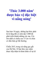
7.1 Test Apparatus, made of Schedule 80 PVC pipe pieces
and constructed as shown in Fig. 1.
7.2 Masking Tape.
7.3 TFE-Fluorocarbon or Polyethylene Spacers, three, 51
by 19 by 3 mm (2 by 0.75 by 0.125 in.).
7.4 Circulating Hot-Air Oven.
7.5 Portland Cement, high early strength, conforming to
Specification C 150, Type III.
7.6 Fine Aggregate, conforming to Specification C 33.
7.7 Source of Regulated Compressed Air, capable of at least
45 psig.
7.8 Molds, eight, 102 by 50 by 13 mm (4 by 2 by 0.5 in.)
inside dimensions, for casting mortar blocks.
7.9 Epoxy Cement, with gap filling capability, or non-sag
construction mastic.
7.10 Sealing Gaskets, eight, 102 mm (4 in.) outside diameter by 57 mm (2.25 in.) inside diameter by 6 mm (0.25 in.)
thick made of very soft rubber.5
7.11 Vernier Calipers.
3. Terminology
3.1 Definitions—Refer to Terminology C 717 for definitions
of technical terms used in this test method. Some of these are
elastomeric, substrate, waterproofing, and compound.
4. Summary of Test Method
4.1 This test method is conducted in two stages. In the first
stage, the test membrane is subjected to hydrostatic pressure
that is increased steadily over an 8 h period until the specimen
fails or the maximum pressure is achieved. In the second part
of the test, three more specimens are subjected to hydrostatic
pressure that is increased slowly from 50 % of the failure value
to failure in 2.5 psi increments every two to three days.
5. Significance and Use
5.1 This test method is used as a screening tool to determine
8. Preparation of Substrates
8.1 Mix 1 part by weight of Portland cement with 2 parts by
weight of fine aggregate and stir in approximately 0.7 part by
weight of water to produce a uniform mixture.
1
This test method is under the jurisdiction of ASTM Committee C-24 on
Building Seals and Sealants and is the direct responsibility of Subcommittee C24.80
on Building Deck Waterproofing Systems.
Current edition approved June 10, 2000. Published August 2000. Originally
published as C 1306–95. Last previous edition C 1306–95.
2
Annual Book of ASTM Standards, Vol 04.02.
3
Annual Book of ASTM Standards, Vol 04.01.
4
Annual Book of ASTM Standards, Vol 04.07.
5
Adco SP 505 and Ashland Plioseal T408 rubber sealing tapes have been found
suitable for this purpose.
Copyright © ASTM, 100 Barr Harbor Drive, West Conshohocken, PA 19428-2959, United States.
1
C 1306
turer, use the primer as instructed by the membrane manufacturer.
10. Procedure
10.1 Application of the Membrane to the Test Substrate:
10.1.1 Prepare four specimens. One will be used for the
rapid screening test and the others will be used for the longterm
test.
10.1.2 Measure the thickness of each block to the nearest
0.025 mm (0.001 in.), using vernier calipers. Record this value.
10.1.3 For self-leveling membrane materials, lay the bound
blocks on a sand bed and level them. Apply 50 mm (1 in.) wide
masking tape around the perimeter of the joined test substrates
so that approximately half of the width of the tape protrudes
above the test surface on all four sides to form a dam. Add
sufficient material to yield a dry film thickness of 1.5 6 0.1 mm
(0.060 6 0.005 in.). Check the coating thickness with a wet
film gage. The film thickness may be built up in several coats
if specified by the manufacturer.
10.1.4 For non-sag materials, stretch a rubber band around
the perimeter of the substrate to keep the joint closed. Apply a
film of membrane at a dry film thickness of 1.5 6 0.1 mm
(0.060 6 0.005 in.). Ensure that the material is a uniform
thickness by using a draw-down bar or similar device.
10.1.5 Allow the membrane to cure one week at room
temperature and 50 % relative humidity followed by one week
in an oven at 70°C (158°F). Remove the test specimens from
the oven and allow them to cool to room temperature for at
least 1 h. Lay the specimens with membrane surface down on
release paper.
10.1.6 Using vernier calipers, carefully measure the thickness of the substrate-membrane composite on either side of the
joint. Measure to the nearest 0.025 mm (0.001 in.). Avoid
stretching or tearing the membrane while measuring the
thickness. Record these measurements.
10.1.7 Remove all masking tape. Insert a TFE-fluorocarbon
or polyethylene spacer into the center of the joint of one of the
membrane-mortar composites, leaving a cavity 3 by 25 mm
(0.125 by 1 in.) at either end of the joint. Make sure the spacer
is touching the membrane but does not cut it. Fill the cavities
on either side of the spacer with premixed epoxy cement or
construction adhesive (such as Liquid Nails6 brand).
10.1.8 The specimen may have to be clamped to keep it flat.
Clamp it with “C” clamps or a heavy piece of angle iron. Place
the angle iron with one side resting on either side of the joint
to form an inverted “V” with the point above the joint.
10.1.9 Allow the cement to cure for one day. Remove the
clamps and spacer.
10.2 Conduct Rapid Test:
10.2.1 Install one membrane-mortar composite in the test
apparatus by placing one sealing gasket on top of the membrane and one sealing gasket under the test specimen. Place the
test specimen with membrane side up in the test apparatus and
draw down on the bolts to a snug fit.
NOTE 1—All parts made of schedule 80 PVC.
FIG. 1 Testing Apparatus
8.2 Pour the mixture into the mold and allow to cure one
day at 100 % relative humidity followed by six days in tap
water, both at standard temperature.
NOTE 1—Prepare enough mortar to produce four blocks, each measuring 101 by 101 by 12 mm (4 by 4 by 0.5 in.).
8.3 Cut or grind the test surfaces of the mortar blocks to
remove laitance and produce a level substrate, free of fins or
burrs. If a release coating is used on the mold, use only the top
surface of the mortar blocks, not exposed to the release coating,
as the test surface. Cut the blocks into matching pairs each
measuring approximately 101 by 50 by 12 mm (4 by 2 by 0.5
in.).
8.4 When a quantity of blocks is prepared, store them in
saturated lime water until needed.
8.5 Rinse any residue from the substrates with tap water and
allow them to dry overnight in an oven at 70°C (158°F)
minimum.
8.6 Other substrates may be used, and shall be prepared to
provide a clean, level test surface. Other preparation requirements shall be as agreed upon between the supplier and the
specifier.
9. Conditioning/Mixing
9.1 Store all materials to be tested at standard conditions of
23 6 2°C (73.4 6 3.6°F) and 50 6 5 % relative humidity for
at least 24 h before any test specimens are prepared.
9.2 Follow the manufacturer’s instructions for mixing and
preparing membrane materials for testing.
9.3 When a primer is required by the membrane manufac-
NOTE 2—Be careful not to use excessive torque which will cause the
6
Liquid Nails brand, available from Macco, has been found suitable for this
purpose.
2
C 1306
DFT 5 measured dry film thickness,
BM 5 thickness of membrane-mortar composite, and
B
5 thickness of block.
test specimen to fracture. See Fig. 1.
10.2.2 Fill the test apparatus with approximately 100 mL of
tap water. Place the tester inside a container to catch water
when failure of the membrane occurs.
10.2.3 Connect the apparatus to a regulated air supply and
apply 0.034 MPa (5 psig) of air pressure. Increase the air
pressure by approximately 0.017 MPa (2.5 psig) every 15 min
until membrane fails or pressure exceeds 0.310 MPa (45 psig).
Water leaking from the bottom of the test apparatus indicates
failure.
12. Report
12.1 Report the following information:
12.1.1 The measured dry film thickness of the membrane as
calculated in 11.1,
12.1.2 The air pressure in megapascals at which the membrane failed or the test was stopped in the rapid test (see
Section 2),
12.1.3 The air pressure in megapascals, at which each of the
three membranes failed, or the test was stopped, in the
long-term test. Also record the average of these three results,
and
12.1.4 The duration of each test in hours or days. Also
report the average of the three results for the long-term test.
NOTE 3—Verify that the membrane has actually failed (and that the
tester has not developed a leak) by adjusting the air pressure to 0.034 MPa
(5 psig) or less, inverting the apparatus, and visually examining the
membrane at the joint.
10.3 Conduct the Long-Term Test:
10.3.1 Repeat the procedures in 10.2.1 and 10.2.2.
10.3.2 Connect the apparatus to a regulated air supply and
apply air pressure at 80 % of failure value determined in 10.2.
Increase the air pressure by approximately 0.017 MPa (2.5
psig) every two days (or three days over a weekend). Continue
the test until the membrane fails or the pressure exceeds 0.310
MPa (45 psig). Water leaking from the bottom of the test
apparatus indicates failure.
13. Precision and Bias
13.1 Repeatability— The repeatability (within a given laboratory) interval for three materials tested by three laboratories
is 14.931 psi. In future use of this test method, the difference
between two test results obtained in the same laboratory on the
same material will be expected to exceed 14.931 psi only about
5 % of the time.
13.2 Reproducibility— The reproducibility (between given
laboratories) interval for three materials tested by three laboratories is 21.082 psi. In future use of this test method, the
difference between two test results obtained in different laboratories on the same material will be expected to exceed 21.082
psi only about 5 % of the time.
NOTE 4—Verify that the membrane has actually failed (and that the
tester has not developed a leak) by adjusting the air pressure to 0.034 MPa
(5 psig) or less, inverting the apparatus, and visually examining the
membrane at the joint.
10.3.3 Repeat this test with the two remaining membranemortar composites.
11. Calculation
11.1 Calculate the measured dry film thickness as:
DFT 5 BM 2 B
(1)
14. Keywords
where:
14.1 hydrostatic; membrane; waterproofing
The American Society for Testing and Materials takes no position respecting the validity of any patent rights asserted in connection
with any item mentioned in this standard. Users of this standard are expressly advised that determination of the validity of any such
patent rights, and the risk of infringement of such rights, are entirely their own responsibility.
This standard is subject to revision at any time by the responsible technical committee and must be reviewed every five years and
if not revised, either reapproved or withdrawn. Your comments are invited either for revision of this standard or for additional standards
and should be addressed to ASTM Headquarters. Your comments will receive careful consideration at a meeting of the responsible
technical committee, which you may attend. If you feel that your comments have not received a fair hearing you should make your
views known to the ASTM Committee on Standards, at the address shown below.
This standard is copyrighted by ASTM, 100 Barr Harbor Drive, PO Box C700, West Conshohocken, PA 19428-2959, United States.
Individual reprints (single or multiple copies) of this standard may be obtained by contacting ASTM at the above address or at
610-832-9585 (phone), 610-832-9555 (fax), or (e-mail); or through the ASTM website (www.astm.org).
3