Jis a 5373 2010
Bạn đang xem bản rút gọn của tài liệu. Xem và tải ngay bản đầy đủ của tài liệu tại đây (3.1 MB, 24 trang )
97
A 5373 : 2010
Annex E (normative)
Piles
E.l
Outline
‘This Annex specifies Group I and Group II of piles which are used mainly for the
foundation piles among the PC products specified in this Standard.
E.2
Classification
The classification of piles shall be as specified in table E.1.
In addition, Group I shall be as specified in table E.2.
Table E.1
Major division
Piles
Minor division
Prestressed concrete pile (PC pile, ST pile, knot pile)
Prestressed reinforced concrete pile (PRC pile, PRC knot pile)
Others
Table E.2
Classification
Prestressed concrete pile
Classification of piles
Classification of Group I
Division by external
diameter
mm
of piles
Division by effective
prestress
Nim?
Detail
See recommended
specification E-1.
406109
800;ta 1-20),
(PC pile, ST pile, knot pile)
— The effective prestress shall be obtained by calculation. The calculated value shall be
in the range of +5 % of each value.
— The PC pile has the same cross section over the entire length. ‘The ST pile is a PC pile
having the cross section which enlarges toward on one end. The knot pile is a PC pile
of which the body is provided with knots.
NOTE: The piles of external diameter exceeding 1 200 mm may be adopted. In this case,
performance values shall be according subject to the agreement between the parties concerned with delivery.
E.3.
Performance
E.3.1 Performance of body of piles
‘The performance of body of piles shall conform to the provisions of table E.8.
In addition, the performance items of Group II shall be subjected to the agreement
between the parties concerned with delivery.
98
A ö378 : 2010
Table E.3
Performance item
;
Service stage
performance
End stage
oe
a
Dureballty
i
een
Performance of body of piles
Performance
Shall be safe to the regular load assumed at the
Performance check method
time oftê use, and crack width shall be less than the | See design document or E.6.
permissible value.
Shall ee
not break due to the load assumed at the time See design
: document or E.6.
Durability shall be secured against deterioration | See design document or
assumed.
actual results.
Workability for transportation, installation,
See design document or
assembly, ete. shall be secured,
actual results
Notes *” Confirmation of the end stage performance shall be made when requested by the purchaser.
» Durability may be confirmed by the actual results of such similar products as are equivalent in terms of water-cement ratio and/or covering of reinforcing bar, ete.
E.3.2 Performance of joint part
The performance of joint part shall be as follows.
a) Bending strength of joint part The joint part shall not break when it is subjected to the break bending moment of the end stage performance for the body
specified in E.8.1.
b) Conneetivity (squareness ofjoint endface) The joint end face shall be at right
angles with the pile axis line within the deviation of 1 mm per 300 mm.
E.4 Shape, dimensions and dimensional tolerances
The shape, dimensions and dimensional tolerances of piles shall be'as follows. As
to Group I, if the design concept is not different, and if the performance (quality) and
the performance (quality) check method are the same, the reference dimension may
be changed within +10 % in response to the purchaser’s demand, provided that the necessary performance (quality) is satisfied.
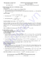
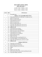
a) Shape An example of shapes of piles is shown in figure E.1.
APC pile and a PRC pile have a hollow cylinder body, having a suitable tip, a
joint or a head, if needed. An ST pile has a diameter enlarged part at its end.
The maximum length of the diameter enlarged part shall be twice the external diameter of the diameter enlarged part. Also, an ST pile may be provided with a
suitable tip, a joint or a head, if needed. Moreover, a knot pile is a PC pile of which
the body is provided with knots. The outside diameter of the knot part shall be
in the range in which the performance of the body is not compromised. Also, the
knot pile may be provided with a suitable tip, a joint or a head, if needed.
99
A 5373 : 2010
Length
Pile
Va end face
4
|
TT
Thick-
External
diameter
Pile end face
Tip o joint
Head or joint
a) PC pile, PRC pile
Thick
meee
External
diameter
Pile end face
Body
fl Head or joint
Enlarged part,
‘Tip
b) ST pile
Pile
end face
‘Thick
ness
External
diameter
Pile end face
Head or joint
‘Tip or joint
©) Knot pile
Figure E.1 Example of shapes of piles
b) Dimensions and dimensional tolerances
erances of the products classified into Group
‘The dimensions and dimensional tolerances of
shall be subjected to the agreement between
The dimensions and dimensional tolI shall be as specified in table E.4.
the products classified into Group II
the parties concerned with delivery.
100
A 5373: 2010
Table E.4
Dimensions and dimensional tolerances of piles
5
Classification
External diameter
‘Thickness
Length
mm
mm
m
imensione || 300
4 toto 15
`
ae
Dimensions
tan to799less | 700 to 1200 | 60 to 230
(PC piles, ST piles, knot piles) —
+5
+7
+Not specified | +0.3 (%)
-2
-4
-0
of length
— The length of a pile shall be designated in increments of 1 m.
— The outside diameter of a pile shall be the average of two values measured along the axis
perpendicular to a cross section of the body.
— The thickness of a pile shall be the average of four values measured along the axis perpendicular to a cross section of end face of the body.
E.5
Bar arrangement (position of prestressing tendon and reinforcing bar)
The bar arrangement shall be as specified in JIS A 5864 and a design document.
However, according to the agreement between the parties concerned with delivery, the
bar arrangement other than that of the recommended specification may be adopted in
the range in which the product performance (including the provisions of E.3) is not
compromised. For the bar arrangement of the piles, the manufacturer shall define the
bar arrangement so as to satisfy E.8 for each product.
E.6
Test method
E.6.1 Compressive strength test
The compressive strength test shall be as specified in JIS A 1182 and JIS A 1108,
or JIS A 1136.
E.6.2 Bending strength test
The bending strength test shall be as specified in JIS A 5368 and as follows.
The tester shall be of Class 1 or superior specified in JIS B 7721, or shall be at
least equivalent in allowance thereto.
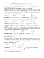
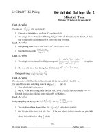
a) The bending strength of body shall be tested as shown in figure E.2. The length
of 8/5 of pile length L shall be supported as a span B, the force F shall be applied
at the centre of the span, and the loading force F shall be calculated from the
bending moment according to the following formula.
If there is a possibility that a local break is likely to occur at the loading point
or the fulcrum before the bending break occurs on a pile, countermeasures shall
be taken.
_ 40M - mgL
6L—10A
where,
F:_ loading force (KN)
N: bending moment (kN+m)
mm: mass of pile (t)
101
A õ373 : 2010
g: standard acceleration of gravity (9.81 m/s*)
L: length of pile (m)
A: bending span (m) A=1.0
‘Span B=3/SL
Figure E.2
lobe
| Force F
+
Loading method of bending strength test
When the effect ofa shear force seems to become large at the time of the bending strength test, the length of span B may be made larger than 3/6 the length L
ofa pile. In this case, the loading force shall be calculated from the bending moment
according to the following formula.
ig(2.
2(B„
M
m:
4)
: loading force (kN)
: bending moment (kN-m)
mass of pile (t)
: standard acceleration of gravity (9.81 m/s?)
: span (mm)
L : length of pile (m)
A: bending span (m) A=1.0
b) The pile shall be confirmed that it does not break when it is subjected to the force F
equivalent to the break bending moment.
c) For the bending strength test of joint, the seam of joint shall be made coincident
at the centre of span, then, the procedure of a) and b) shall be conducted.
g
B
E.6.8 Axial-tension bending strength test (positive/negative alternating repetition axial-tension bending strength test)
The axial-tension bending strength test shall be as follows.
‘The tester shall be of Class 1 or superior specified in JIS B 7721, or shall be at
least equivalent in allowance thereto.
a)
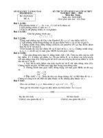
For the axial-tension bending strength test of the body, as shown in figure E.3,
the span part of B of the pile with the axial-tension N shall be supported, and the
102
A 5373 : 2010
force F shall be applied at the centre of span. According to the following formula,
the loading force F shall be calculated from the bending moment.
If there is a possibility that a local break is likely to occur at the loading point
or the fulcrum before the bending break occurs on a pile, countermeasures shall
be taken.
In the case of a positive force,
pa 8M =mgQB-L
2(B- A)
In the case of a negative force,
IM — mg (24-1) +8_ yg
F: loading force (kN)
: bending moment (kN+m)
s
=
where,
2(B-A)
: mass of pile (see values in of recommended specification E-1 table 5) (t)
standard acceleration of gravity (9.81 m/s)
length of pile (m)
span (m) B27.0
relative deflection of centre part (m)
axial-tension (kN)
A: bending span (m) A=1.0
zZowne
:
:
:
:
:
b)
The axial-tension N, loading force F, and positive/negative alternating number of
cycles shall satisfy the following conditions.
1) The axial-tension N shall be secured constant till the completion of test.
2) The axial-tension N shall be either of three steps, Ni, Nạ, and N;, which are shown
in recommended specification.
8) While the axial-tension N is applied, the repeated loading force F shall produce
the moment of 1/1.2 each of the crack bending moment and the break bending
moment. The number of cycles shall be 10 or more.
One cycle is defined as one positive/negative sequence.
©) It shall be confirmed that the pile does not break when it is subjected to the force F
equivalent to the break bending moment after the completion of positive/negative
alternating repetition.
In addition, the loading force F shall be calculated according to the formula specified in a).
103
A 5378 : 2010
Positive
force F
Axial-
tensionN
4
=
Axial-
âm
tensionN
cÂNegative
force F
Span B
L.
Figure E.3
Loading method of axial-tension bending strength test
E.6.4 Shear strength test
The shear strength test of body shall be as specified in JIS A 5868 and the following.
The tester shall be of Class 1 or superior specified in JIS B 7721, or shall be at
least equivalent in allowance thereto.
‘The shear strength test of body shall be conducted using the method shown in
figure E.4 or figure E.5. When using the method shown in figure E.4, the loading force
shall be calculated from the shear strength according to the following formula.
If there is a possibility that a local break is likely to occur at the loading point or
the fulcrum before the shear break occurs on a PC pile, countermeasures shall be taken.
F=20
where,
F: loading force (kN)
Q: shear strength (kN)
ForceF
5
ql
|
te
7
b
Z
al -
bg)
bp
1
¡ z2z
ea
L
b : bending span (loading span) (m) 6=1.0
a: shearing span (m) a=1.0D
D: external diameter (m)
Figure E.4 Loading method of shear strength test (loading by
simple beam form)
104
A 5373 : 2010
In addition, the ejection length (m) of the sample shall be about 1.25D to 2.0D.
Especially, when conducting a shear break test, it shall be as specified in figure E.5,
and the loading force shall be calculated from the shear strength according to the following formula.
pu gare
where,
b
F: loading force (kN)
Q: shear strength (kN)
b: distance between loading point and outside fulcrum
(m)
a: shearing span (m)
+: thickness (m)
D:
a=D-1/2
external diameter (m)
Force F
`]
|
|
[|
b
I
zm
2a
b
L
b : bending span (loading span) (m) b= 1.0
a: shearing span (m) a=1.02
D: external diameter (m)
Figure E.5 Loading method of shear strength test (loading by
overhang beam form)
E.6.5 Measuring method of squareness of joint end face
For the measurement of squareness of the joint end face, a square shall be set as
it in line with the axis of external diameter of a pile, and the amount of inclinations
about the external diameter of a pile shall be measured.
E.7 Quality of concrete
E.7.1
Material and production method
The material for concrete and the production method shall be as specified in JIS
A 5364.
105
A 5373 : 2010
E.7.2 Compressive strength
The compressive strength of concrete shall be verified by the compressive strength
of the sample which has been processed by the same curing as the product or the compressive strength which has been controlled properly. When the predetermined material aging is finished, the strength shall be 80 N/mm’ or more for the effective prestress
of 4.0 N/mm’, and the strength shall be 85 N/mm’ or more for the effective prestress
of over 4.0 N/mm®.
Moreover, the compressive strength at the time of prestress intro-
duction shall be 40 N/mm? or more.
In addition, products of Group II shall be subjected to the agreement between the
parties concerned with delivery and the compressive strength of concrete may be as
specified in AnnexA of JIS A 5364.
E.8_ Inspections
Inspections shall be as specified in JIS A 5365 and the following.
a) Final inspection The final inspection of piles shall be conducted for the appearance, performance, shape and dimensions, and shall be as follows.
1) Appearance For the appearance, it shall be a 100 % inspection or a sampling
inspection in consideration of the characteristics of product, manufacturing
method, production quantity, ete.
2) Performance, shape and dimensions For the performance, shape and dimensions, the inspection shall be a sampling inspection.
When the performance is inspected by a sample as alternative characteristies, the correlation between the sample and the product shall be established.
3) Size of inspection lot The size of inspection lot shall be determined by the
manufacturer in consideration of the characteristics of product, manufacturing
method, production quantity, production period, ordered quantity, ete.
Any product in the inspection lot shall have the same characteristics, and shall
be manufactured using the same materials, conerete mix proportion and manufacturing process, ete.
b) Delivery inspection The delivery inspection of piles shall be conducted for the
appearance, shape and dimensions. The size of inspection lot and the sampling
method shall be subjected to the agreement between the parties concerned with
delivery, and shall be specified by the purchaser. ‘The delivery inspection may be
omitted subjected to the agreement between the parties concerned with delivery.
E.9
Marking
‘The marking items on piles shall be the following as specified in JIS A 5861. Moreover, the PC pile, ST pile and knot pile among the piles manufactured by centrifugal
force compaction shall be marked as PHC.
a)
Classification or its abbreviation
b)
Manufacturer’s name or its abbreviation
c)
Date of manufacture or its abbreviation
106
A5373 : 2010
E.10 Others (recommended specification)
Group I of covered conduits is shown in table E.5.
Table E.5 Recommended specification
‘Structure-specifie product group standard
JIS A 5373 | Annex E Piles
Recommended specification
Recommended specification E-1
Prestressed conerete piles
107
A 5878 : 2010
Recommended
Prestressed
specification E-1
concrete piles
E-1.1 Outline
This recommended specification describes the prestressed concrete piles in Group I
of piles (hereafter referred to as “PC piles”) in Annex E. The pile with diameter enlarged part at its end (ST pile) and that provided with knots on the body (knot pile)
are included.
E-1.2 Classification
PC piles shall be classified, by the external diameter, into 300 mm, 350 mm, 400 mm,
450 mm, 500 mm, 600 mm, 700 mm, 800 mm, 900 mm, 1000 mm, 1100 mm and
1200 mm. Moreover, they shall be classified, by the magnitude of effective prestress,
into Class A, Class B, and Class C (hereafter referred to as “A, B and C”, respectively).
In addition, the effective prestress of A, B and C of PC piles shall be 4.0 N/mm’,
8.0 N/mm? and 10.0 N/mm’, respectively.
E-1.3
Performance
E-1.3.1 Bending strength
The bending strength of the pile body and the pile joint shall be as follows.
a)
Pile body
The PC pile body shall be subjected to the bending strength test as
specified in E-1.6.2. When it receives the crack bending moment specified in recommended specification E-1 tables 1 and 2, it shall not produce any crack. Also,
the PC pile body shall not break with the value of break bending moment specified in recommended specification E-1 tables 1 and 2.
b) Pile joint The PC pile joint shall be subjected to the bending strength test specified in E-1.6.2 and shall not break with the value of break bending moment specified
in recommended specification E-1 table 1.
E-1.3.2 Shear strength
The PC pile body shall be subjected to the bending strength test as specified in
E-1.6.4. When it receives the shear crack strength specified in recommended specification E-1 table 3, it shall not produce any crack. Moreover, it shall not break with
the value of shear break strength specified in recommended specification E-1 table 3.
E-1.8.3 Connectability (squareness of joint end face)
‘The joint end face shall be at right angles with the pile axis line within the deviation of 1 mm per 300 mm.
108
A 5373 : 2010
Recommended specification E-1 Table 1 Dimensions and bending strength
(at application of axial-tension N= 0 kN)
External | Divi- | Thick- | Length | Crack
Break |} External | Divi-| Thick- } Length | Crack
Break
điameter | sion | ness
bending | bending || diameter | sion | ness
bending | bending
mm
mm
A
4to13
B
300
pee |e
m
60
aes
G
A
350
37.3
34.3
61.8
39.2
78.5
34.3
52.0
49.0
88.3
58.9
117.7
73.6
132.4
c
88.3
176.6
A
73.6
110.8
i
B
65
B
500
24.5
4to15
60
c
450
kKN+m
4to13
B
400
kN-m
4to15
T0
eed
mm
700
B
100 | 4to 15
A
800.
B
110 | 4to 1õ
i
Cc
900
372.8
671.0
4414
882.9
392.4
588.6
539.6
971.2
fan ae
735.8 |
1324
c
833.8 |
1668
A
735.8 |
1104.
194.2
245.2
C
A
103.0
155.0
A
120 | 4to lỗ
B
130 | 4to15|
1030
1854
1177
2354
932.0 |
147.2
264.9
1324
2384
166.8
333.5
c
1621
3041
A
166.8
250.2
A
1177
1766
1668.
3002
1962
3924
B
90
4tol5|
c
245.2
4414
284.5
569.0
B
1200
140 | 4tolõ |
1398
c
600
1100
39743
1275
B
1000
kN-m
264.9
637.6 |
122.6
4to 1
kN+m |
c
107.9
80
sea [oe
m
A
c
B
4to 18
aval
mm
B
150 | 4tolõ |
c
Informative example
Ẹ
teh
`
¡|
FB
| 3>
|
Lf |
~2000—10000
fet
biting mimont uN
Break bending moment My
N,N;
10002000
/2
3000
4000
(Tensile force) (Compressive force)
Axial directional force N (KN)
2
Me
AY
fifi’
oD
đua)
Lo faN
SPOS
c
5000
External diameter 400 mm axial force,
bending moment relationship diagram
6000
=5 000
2
⁄
⁄
[KIN
crack bending moment Me
| Break bending moment My
Ml
0
Nol
5000
Ns
10000
15000
(Tensile force) (Compressive force)
Axial directional foree NV (kN)
External diameter 800 mm axial force,
bending moment relationship diagram
20 000.
109
A 5373 : 2010
Recommended
specification E-1 Table 2
Axial-tension bending strength
External [Divi-|
Bending strength at
Bending strength at
diameter | sion | application of axial-tension N, | application of axial-tension WN: |
‘Axial- | Crack | Break | Axial- | Crack | Break |
tension | bending | bending | tension | bending | bending |
| moment | moment | ạ, | moment| moment|
Mẹ
Me
Me
Mẹ
kN | Nem | Nem | KN | kNem | Nem |
mm,
300 | A | 3924|
441|
775 | 7848|
647|
1059|
5
540 |
952
746 | 1177
6
589 | 1069
795 | 1286
350 | A | 4905|
667]
118|
98L0|
961[
1560|
1786
|
1099
M03
|
795
5
c
998 | 159.9
1197|
1844
400 | A | 5886|
971|
1688 |1177 | 1893|
2237|
B
167 | 2011
1689 | 249.2.
e
1305
[2345
1786 | 266.8
460 | A | 7868|
1844|
2286 |1472 | 1952|
3129|
B
1687 | 2914
2296|
8532
c
1884 | 3296
2443|
8757
42L8|
3041|1766 | 2689|
1834|
500 | A | 8829|
B
2276 | 302.4
3090|
483.6
c
2472|
4473
3986 | 6180
600 | A | 1275 | 3080|
5229| 2651 | 4522|
7230|
B
3885
[671.0
5807 | 823.1
€
4217|
765.2
5709|
8770
700 | A | 1766 | 4983|
8829| 8582 | 78L8|liZI |
5
6063 | 1084
8407 | 1282
G
6789 | 1185
9064 | 1885
800 | A | 1962 | 6926|1143 | 3924 | 99L8|1679 |
B
8897 | 1446
1140 | 1796
1286 | 1936
985.9 | 1679
¢
900 | A | 2452 | 9663| 1598 | 4905 | 1394 | 2226 |
B
1165 | 2009
1595 | 2816
e
1264 | 2277
1696 | 2679
1000 | A | 2943 | 1306 | 2159 | 5886 | 1876 | 3004 |
B
1898 | 2750
2167 | 3403
€
1146 | 314
2814 | 3633
1100 | A | 3434 | 1652 | 2821 | 6867 | 2372 | 3943 |
B
2030 | 3646
2785 | 4588
c
2318 | 4163
2916 | 4846
1200 | A | 3924 | 2080 | 3555 | 7848 | 2982 | 4983 |
B
2552 | 4598
3485 | 5784
€
2884 | 5831
3706 | 6208
Bending strength at
application of axial-tension Ns
Axial- | Crack | Break
tension | bending | bending
„; | moment | moment
Mer
My
KN | kNim | kNim
1177|
844|
1226
942 | 1275
991 | 1805
1472|
1285|
1815
1419 | 1884
111 | 1988
1766 | 1825|
2590
2021|
2698
2168 | 2776
2207|
2560|
361.0
2904 | 3796
301 | 3895
4964
3453|
2649|
3895 | 5278
4091|
6435
3826 | 59/5 | 8397
6739 | 8868
7182|
9094
5297|
9653 | 1312
1074 | 1366
1189 | 1387
5886 | 1292 | 1855
1440 | 1967
1584 | 2027
7358 | 182 | 2601
2024 | 2748
2127 | 2837
8829 | 2446 | 3502
2786 | 3697
2882 | 3810
10300 | 3092 | 4597
3440 | 4907
3612 | 6041
11770 | 3985 | 6852
4819 | 6272
4518 | 6471
When the performance check of the PC pile body involves the axial-tension bending strength test and
the positive/negative alternating repetition axial-tension bending strength test, the representation external diameter shall be around the middle diameter of piles which are usually manufactured. The axial tension
at this time shall be Ns.
In addition, the length of PC pile used in this case shall be 8 m or more.
110
A 5373 : 2010
Recommended
‘Symbol
Ny
specification E-1 Table 2
(concluded)
Explanation
Axial-tension which almost equivalent to each break bending moment of A, B, and C in
axial-tension and bending moment relationship diagram
‘Ny_ _|
Axial-tension of Nix 3/4
Nz __| Axial-tension of Nex 2/4
Mì — | Axialtension of N,x1⁄4
Symbol
‘Me — | Crack bending moment
Mụ —_ | Break bending moment
Explanation
111
Á 6373 : 2010
Recommended
specification E-1 Table 3
External diameter
‘Thickness
nai
mm
300
350
400
450
500
60
60
65
70
80
Division
90
700
100
800
110
900
1000
1100.
1200
120
130
140
150
Shear break strength
Shear crack
kN
Shear break
A
99.1
125
B
126
160
c
136
175
A
119
149
B
c
160
168
190
209
A
148
187
B
187
234
G
204
259
A
181
225
B
228.
293
c
248
316
A
229
276
B
288.
359
c
314
395
B
392
506
A
600
Shear break strength
3
388
c
428
554
A
406
514
B
c
A
B
512
557
512
647
677
c
704
936
A
631
820
B
T97
1063
c
867
1153
A
762
990.
B
961
1289
c
1047
1400
A
905
1202
B
1142
1561
c
1244
1687
A
1059
1413
B
1337
1823
c
1457
1979
739
661
863
‘When the performance check of the PC pile body involves the shear test, the
representative external diameter shall be around the middle diameter of piles
which are usually manufactured.
112
A 5373 : 2010
E-1.4 Shape, dimensions and dimensional tolerances
The shape, dimensions and dimensional tolerances of PC piles shall be as specified
in recommended specification E-1 figure 1, and recommended specification E-1 tables
1 and 4.
If the reference dimension is changed within the range as specified in E.4, the manufacturer shall present the data indicating that PC piles conform to E.8 by the design
document or the performance test when requested by the purchaser.
A PC pile has a hollow cylinder body, having a suitable tip, a joint or a head, if
needed.
An ST pile is a PC pile having a diameter enlarged part at its end. The maximum
length of the diameter enlarged part shall be twice the external diameter of the di-
ameter enlarge part.
A knot pile is a PC pile of which the body is provided with knots. The external
diameter of a knot part shall be in the range in which the performance of the body is
not compromised, and for that whose external diameter is 450 mm or less, it shall be
not more than the said external diameter + 150 mm, and for that whose external diameter is 500 mm or more, it shall be not more than the said external diameter
+200 mm. Moreover, the interval between knot parts shall be 1 m.
A tip, a joint and a head are included in the length of PC pile. A metallic fixture,
which is attached to the tip after manufacture,
is not included in the length of pile.
‘There are a closed edge and an open edge. A tip may be attached to a upper pile or a
middle pile to make a lower pile.
113
A 5373 : 2010
Length
Thick
ness
External
diameter
Pile end face
/
Pile
end face
Tip or joint
PC pile
Length
External
diameter
Pile end face
Enlarged part,
Body
Head or joint
ie
ST pile
Length
External
diameter
Pile end face:
‘Thickness
Pile
end face
Body
[ Head or joint
‘Thickness
Va
l Head or joint
Knot pile
‘Tip or joint
Recommended specification E-1 Figure 1 Shape of pile
114
A 5373 : 2010
Recommended specification E-1 Table 4
Dimensions and dimensional tolerances
A
Classification
External diameter
‘Thickness
Length
mm
mm
m
Prestressed concrete pile
[Dimensions | 3000 600 | 700to1200 | 60 to i50,
4to 15
(PC pile, ST pile, knot pile) | Dimensional
+5
+7
+Not specified | +0.3 (%)
tolerances
-2
~4
-0
of length
— ‘The length of a pile shall be designated in increments of 1 m.
— The outside diameter of a pile shall be the average of two values measured along the axis
perpendicular to a cross section of the body.
— The thickness of a pile shall be the average of four values measured along the axis perpendicular to a cross section of end face of the body.
E-1.5 Bar arrangement
The bar arrangement of PC piles shall be as follows.
a) As to the prestressing tendon and reinforcing bar arranged in axial direction, the
ratio of reinforcing bar in terms of total cross-sectional area shall be 0.4 % or more,
and the number shall be six or more. On each cross section of pile, they shall be
arranged as uniformly as possible along the circumference of concentric circles. This
is intended to decrease directionality of the bending strength of a pile. The gap
of prestressing tendon and reinforcing bar shall be one or more times their diameters, and more than 4/3 of the maximum dimension of a coarse aggregate.
b) A spiral reinforcing bar shall be arranged on the outside of prestressing tendon
in axial direction and reinforcing bar in axial direction. The wire diameter of spiral
reinforcing bars shall be 3 mm or more for the pile of 500 mm or less in external
diameter, 4 mm or more for the pile of 600 mm to 1 000 mm in external diameter
and 5 mm or more for the pile of 1 100 mm to 1200 mm in external diameter. The
pitch shall be 110 mm or less.
The required quantity of spiral reinforcing bar for improvement of the shear resistance and the deformation performance shall be subjected to the agreement
between the parties concerned with delivery.
©) The covering of prestressing tendon and spiral reinforcing bar shall be more than
15 mm.
4) A reinforeing bar and prestressing tendon shall be free from loose scale, oil, ete.
which damage adhesion of concrete, and shall be assembled and fixed to the right
position.
E-1.6
Strength test
E-1.6.1 Compressive strength test
The compressive strength test of concrete shall be as specified in E.6.1.
115
A 5373 : 2010
E-1.6.2 Bending strength test
‘The bending strength test shall be as specified in E.6.2.
In addition, the mass of PC pile body used for calculation of a loading force may be
as specified in recommended specification E-1 table 5.
E-16.3 Axial-tension bending strength test
The axial-tension bending strength test shall be as specified in E.6.3.
In addition, the mass of the body of PC pile used for calculation of a loading force
may be as specified in recommended specification E-1 table 5.
E-1.6.4 Shear strength test
‘The shear strength test shall be as specified in E.6.4.
E-1.6.5 Measurement test of squareness of joint end face
‘The measurement test of the squareness of a joint end face shall be as specified in
E.6.5.
Recommended
specification E-1 Table 5
External
Mass of PC piles
Mass® +
diameter
Tength
mm | 4m | 65m | 6m | Tm | 8m | 9m | 10m | lim | 12m | l8m | 14m | 16m
300 | 0.470 | 0.588 | 0.705 | 0.823 | 0.940] 1058| 1176| 1293| 1411| 1528| 1.646| 1/763
350 | 0868 | 0.710 | 0.852 | 0.994 | 1.136| 1278| 1421| 1563| 1.705] 1.847 1.989] 2.181
400 | 0711 | 0.889 | 1.067 | 1.244 | 1422| 1600| 1778| 1955| 2.133| 2.311| 2.489| 2.667
450 | 0869 | 1086 | 1.303 | 1520 | 1737| 1954| 2.172| 2.889 2.606| 2.823| 3.040| 3.257
500 | 1097 | 1373 | 1/646 | 1920 | 2.194| 2469| 2.743] 3.017| 3.292| 3.666| 3.840| 4.115
600 | 1.499 | 1874 | 2248 | 2.623 | 2.998| 3.373| 3.747| 4.122| 4.497| 4.871| 5.246] 5.621
700 | 1.959 | 2.449 | 2.939 | 3.429 | 3.919| 4409| 4.898| 5.388| 5.878| 6.368| 6.858| 7.348
800 | 2.479 | 3.098 | 3.718 | 4.838 | 4957| 5.577| 6.196| 6/816| 7436| 8.055| 8.675] 9.205
900 | 3.057 | 3.821 | 4585 | 5.349 | 6.113| 6877| 7642| 8.406| 9.170| 9.934 |10.698 | 11-462
1000 | 3.693 | 4.617 | 5.540 | 6.463 | 7387| 8.310| 9.233 | 10.157 | 11.080 | 12.004 | 12.927 | 13.850.
1100 | 4.389 | 5.486 | 6.583 | 7.681 | 8.778| 9.875 | 10.972 | 12.070 | 13.167 | 14.264 | 16.361 | 16.459.
1200 | 5.143 | 6.429 | 7.715 | 9.001 | 10.287 | 11.672 | 12.858 | 14.144 | 15.430 | 16.716 | 18.002 | 19.287
Note ® For the purpose of convenience, the mass is calculated by the following formula assuming that the unit volume mass of PC piles is 2.60 t/m®, and the value ofx is 3.14. The
value of mass is rounded off to the third decimal place in accordance with JIS Z 8401.
m= watL (D-t)
where,
m:
©:
ty
L:
D:
mass of PC pile (t)
unit volume mass of PC pile (t/m®)
thickness (m)
length (m)
external diameter (m)
116
A 5873 : 2010
E-1.7 Quality of conerete
The compressive strength of concrete shall be as specified in E.7.2.
In addition, Class A shall be 80 N/mm? or more, and Class B and Class C shall be
85 N/mm? or more.
E-1.8 Inspections
E-1.8.1 Inspection items
The inspection items of PC piles shall be as follows.
a) Final inspection The final inspection items shall be as follows.
1)
Appearance
2) Performance
3) Shape and dimensions
b) Delivery inspection
The delivery inspection items shall be as follows. How-
ever, the delivery inspection may be omitted according to the agreement between
the parties concerned with delivery.
1) Appearance
2)
Shape and dimensions
E-1.8.2 Inspection lot
‘The size of inspection lot of PC piles shall be decided by the manufacturer for final
inspection, and by the purchaser for delivery inspection according to the agreement
between the parties concerned with delivery by considering characteristics of the product, production method, production quantity, production period, ordered quantity, ete.
One inspection lot may consist of 3 000 units or fraction thereof.
E-1.8.3 Inspection method
The inspection method of PC piles shall be as follows.
a) Final inspection The final inspection method shall be as follows.
1) Appearance For the inspection of appearance, the lot shall be subjected to
100 % inspection by visual observation, and those conform to the provisions of
5.1 shall be accepted.
2) Performance For the inspection of the bending crack strength of the body, two
arbitrary piles per one lot shall be taken and inspected as specified in E-1.6.2.
If both of the two conform to E-1.8.1, the lot shall be accepted. If neither of the
two conforms, the lot shall be rejected. If only one of the two does not conform,
the lot shall be re-inspected. In the re-inspection, four more piles shall be taken
from the lot, and if all the four conform to the provisions, the lot shall be accepted
after the first non-conforming product is eliminated. If one or more of them do
not conform in the re-inspection, the lot shall be rejected. The bending break
strength of the body shall be inspected as follows. One of the first two piles for
bending crack strength inspection shall be inspected as specified in E-1.6.2.
117
A 5373 : 2010
When it conforms to the provisions of E-1.8.1, the lot shall be accepted. If it
does not conform, two more piles shall be taken from the lot for re-inspection,
and if both of them conform to the provisions, the lot shall be accepted after the
first non-conforming product is eliminated. If one or more of them do not conform
in the re-inspection, the lot shall be rejected.
3) Shape and dimensions For the inspection of shape and dimensions, two arbitrary PC piles per one lot shall be taken. If they conform to E-1.4, the lot shall
be accepted. If one or more of them do not conform, the remainder of the lot
shall be subjected to 100 % inspection, and those conform to the provisions shall
be accepted.
b) Delivery inspection The delivery inspection method shall be as follows.
1) Appearance The appearance shall be inspected in the same way as a) 1).
When adopting the sampling inspection, if two arbitrary piles are inspected
and conformed to the provisions of 5-1, the lot shall be accepted. If one or more
of them do not conform, the remainder of the lot shall be subjected to 100 %
inspection, and those conform to the provisions shall be accepted.
2) Shape and dimensions The shape and dimensions shall be inspected in the
same way as a) 3).
E-1.9 Marking
The PC piles, ST piles and knot piles which conform to all the requirements of this
Standard shall be marked as specified in E.9. The piles manufactured by centrifugal
force compaction shall be marked as PHC.
127
A 5373 : 2010
“aeop opeut
sỊ ouvurgjted pus Ayxpenb
somsse 101] 2ut80 |94916{
poppe
sy Ax9aqT0p EK paused
-uod sonted ayy 9684484,
juowoasBe ayy 07 8upa0228
3090-2840 dpq jo oSueyo
J0 9882 oự) tị uọ)
-oducue weg ¢
Jo worisod) quour
(409012916014
pur [9015 Od
AUP STSINS pouruueyepasd ayy WHA ~"
‘ayox0
11809418 oarssordwog z'1,| -woo jo AEN 1
=
dø\g (Đ|
“+ *paustut sự #0pE
TPHBTEM pourwrojopard ayy wayyy
9i9aouoa
wduans oAesoadtoO Ø8 | - J0 MMBRĐ /d
pasiwioadutoo jou st (g-gL Jo Suo|staoad
ay) Burpnjouy aoueutsojsod jonpoad oy
(aq 8u
‘yoruas ur oBues oy ut poydope oq Kou
uoneaytoods pepuouruiode. 9t] J0 39 | -249jutoa pue uop.
wey) 400110 1020128013 req oy} “Á19AN[ | -u91 ÖutsSoxisaad
-op t[jU/A 9490002 Sfiiød Ø1) o9ax9Q
3090180480 otJ} 0 8u†pa09o9 “oA9A0j{ | -988448 reg oy
“wi [ Jo S4U9191901 tị ĐØ)8U.
-B\sop 9q [124s apd & Jo q3809{ 9qJ, —
(q1 ti04) p29911X4))
NÖM9| j9 () 60
mui
NH8
s8Iđ j0 80201901
IPOtsuouup pưø suoisu9u( ÿ*g 9|q5J,
“papaau jt “peay 6 40.1010Ƒ
dy ojquans ứ tyy4 paptAoad aq 4eut
59009460
id 1003 9411 '09[V. 'p950I04đi09 you
3909490) [8101 SỊ ẤpOQ 9tự] Jo 9909011019đ ayy 214A
Teuorsuounrp
-uounp pue ‘uors uy 0804 04 tị 9d [IE4S 229đ 30031 9
-uowp ‘odeys
y
Jo
10101191
apisyno
oy,
“sous,
Yara
S94 (9A
said (ean | papraod st Kpoq au Yara Jo atid Od
-uriou) g xouuV | © s1 od 10346 49A0940/ ^^ odvyg (@ | -euLI0U) yf xoUUY,
sngio
ssnpio
J9 20H pur ON
30000.
Joann pue “oN
(0105:8289 V SIF) uopitpo 1uoaxn2,
(7008: LES V SIP) UoREpe snorsotg
3890,
5TESBTJT “un tr [ 9q |[ES
apd 9 J0 (389 Jo 2u OMY, T syTeMIOY
(sydsoox9
laoađ ot[ $v poppe
J9 (
3821
atop eta P2199
STL
-uoa saryied ayy r9ôAx19q
309099488 ød} 0) 8utpa0290
Khi
920080301 099 SE Yor
|B0IS.
tí 6 ơ) tí ÿ J0 3809, “D004uị -09uip put Su04SU2u011_ ÿ9008001
9|q51 9 X9uuV.
pu9uiop tyt4a 8u1doox[
“payroods Apxvayo st
30031 9 Jo adeys ou,
‘worstaax 105 uoswoy
128
A ð373 : 2010
† 9[484 [-g uoI9ou.
3891 19418 8uIpuoq 91 ø p2199fqns.
9% IIEs 3u10f 9[Iđ 2d 9MJ, 3049ƒ 9ttd. (4
“TL 91qe) 1-9 uoeayy
-toods popuouruzosax ut paytoads quour
ou 30†pt9q 9A(4904980P 90 D999
1IES 2t “uetjJ, '9 øsnbịo uy pogosds
“payonp
-uoo $1 3893 yonpord ay
uy ‘ayy acy pue yyBueNs
ˆ8 9493 1-€ og9oj†oode pepuot
Borg 1waYs oY) BuIpodoxo
peo 9) Öu1A13 4q u90aq 7.0904 tị p229đ9 90|#A 9411 p999X9 [IS
†ofpoad o1 9tr 0 suo493 (18915 9A†Jon.1)s9p 19918 91 “49A0840[
-ulep SỊ ]{ 0510994 p98IA9ẠT
\#u@41S 499N6 Ø6
'pøianpu0a
st 980} yonpoad oy} wou
'iustiotr #ứniG:
909149494
“6 91493 T-gT 05t,
-pads papuomuiosaa ur poytoads yysueNs
3[204d 40009 J0 Ø0|A 9) 314 31694
you |[8S Ấpoq 9Id Od 9411 *19A0840Jÿ
WiBuozs 48906 ØE1-đ.
“1 8148) T-@ woneoyteds popuour
-10294 ut paryioads yuouour Sut
380 (u91 Öutpuoq 9] ơị p9o9[qns
94 1[49 3u40[ 9fd Od 9dJ, 3410[9[ld (4
"øpue[
E | selqw [-j[ uoJqwoutoods popuetuooax:
3091000,
30 219 pue “oN,
(006:8/89 V SIF) oftpe snotaoa4[
-B040u) g xeuuy:
2snp[p
0u3 puw 9|1d J6
“9[IẲ Qd 91 ⁄49A040W.
1091000.
(0105:6289 V SIP) woRpe 306x4n2.
tung
Moped STH
-B100) g[ XØutV,
sng[s
Joann pur ON,
"§ 9[q81 pư8
Si Papen pon a
soitd oạoze
pogoods 3u9uioui 8utpueq wø9aq,
t
__
|
ejox0
sod
Buyat3 4q woxouq yonpoad | “Peds papwowutooax ur payloads onyea
Jo onyea oy 3A 3[894q 300 [[9q9 | -U09 p9ssoxso4[
sự Bút ơ) snozo8up sỊ | 91 P9999 J[qs u9tiott 3uypt9q 9A, | -uoo passaasaxg[
ẤP94 9Itd Ođ 943 /981V —” £poq 9Ild (# | 1-1 ưoneauroeds
T-g uogygogtosds|
31 Pu 492 opEut sỊ potjstu | “204159p 9t '4oaosaoj4 *' 4po4 9ld (|
Đ9pu9uituo2SL
(38ueits ñu[pU9đ T'ÿT-4[|
P9pU9u099
wpduans 8upu9g T'@|
380 91) 980199 PostAoy
'OHd SE poxzeu:
ˆĐ2ppE 9q ơị 49|2 9pbut
đuPHĐW GÌ — sqtreqsuopyapduios soioytpðnyauso| — SUPP GL
SỊ t01g2đi02 9240] [6Ä
soltd (oan
4q poamasynueur seyd oy Suoure oprd
softd (ea |
-JIH3089 Áq paz39pyn09u
jonpoad yp jo Supjreut our,
.0tS†A94 107 08091
129.
Á ð378 : 2010.
pueuiop 3á 8u1doø3 u[
oad oxy se poppe
Azoatjop is paus99
“I0 sotud 0V] u908442q
0tui9u8g o1} 01 8[p40290
971080204 tro) St 9A
tí 9 0) tí ÿJ0 (18091 “SD094
“pappe st
DIW-"tĩ
ÿ Tư ÿ túỊ 5ỊqBTTĐAE
BIE VTA “yon wr T 9g [PS
aud 8 Jo yrBuay jo yun oy, Ị 944010
(sidsoox0 jens)
ASUS] 30 (GH) BOF
BH
m
X82]
9009490) [euoisuetx
-lP DU Su0Isu2u(1 ÿ 2Q) [- X9uuV.
=
“ur [ Jo 94090191901 tu po†eử
-Bisop 0q [Leys aNd ø J0 3u9[ 9dJ, —
(819 ti0äÿ p912811g))
N29) j9 (46) FOF
si
ur
3091000.
Jo 2108 pur “ON
(OT0Z: 8288 V SIP) 00tp9 39442,
WBue1
8901401 [EU0ISuØ0TD púE SuOjsttiiŒT
ÿ 9|q8/, T-4[ U0fABoi29đS papuotutioaø[
sur T 94 [IES
sqred 30003 00/494 [earoqUt oy} ‘1940
-o10j “tUU QOZ + JayOUIEIp [BUEIxe PIES
‘ou wey] 8400 OU aq {[EYS 4F ‘OIOUr 10
i01 006 SỊ 402901010 [E0191X9 95010 381
seouvio
40} pue ‘wu ST + 4919019p JBU19X9 “l0 [euoys
uoup
—
ous tf) 24001 0 9A [[ES 31 “959],
pies
-ueuuip pu9 u0te
40 tIUI 9ÿ SỊ i 1019110p |P491X9 980A
‘odeys y
-uowp
4poq
st
30u
duro>
“pasruoa
pue
40}
BU}
sod oy019
soqtd 97029 | ou Jo oaupumioyzod oy yorya 0 98094
ay} UI aq [[E(8 148đ 30u34 # Jo 1ø2ugtp | "U99 28594489441
mn pera
jeusoyxe ou, “s}ouy yr
1-8 00fqo†oads |
papuowwioooy,
popusuruoay | Apoq ays tora Jo and Od &
ssnuo
2s
391000.
30.08 pus “oN
(7008: 8289 V SIC) VOLPE solar


![Đề Thi Học Sinh Giỏi HOÁ 12 - Tỉnh Nghệ An - Bảng A [2009 - 2010] ppsx](https://media.store123doc.com/images/document/2014_07/01/medium_OzGpc5hNlY.jpg)