Jis h 3300 2012
Bạn đang xem bản rút gọn của tài liệu. Xem và tải ngay bản đầy đủ của tài liệu tại đây (1.38 MB, 39 trang )
JAPANESE
INDUSTRIAL
STANDARD
Translated and Published by
Japanese Standards Association
JIS H 3300
:2012
(JCBA/JSA)
Copper and copper alloy seamless
pipes and tubes
ICS 23.040.15;77.150.30
Reference number: JIS H 3300 : 2012 (E)
PROTECTED BY COPYRIGHT
20 S
H 3300 : 2012
Date of Establishment: 1977-05-01
Date of Revision: 2012-10-22
Date of Public Notice in Official Gazette: 2012-10-22
Investigated by: Japanese Industrial Standards Committee
Standards Board
Technical Committee on Non-Ferrous Metals
JIS H 3300: 2012, First English edition published in 2013-03
Translated and published by: Japanese Standards Association
4-1-24, Akasaka, Minato-ku, Tokyo, 107-8440 JAPAN
In the event of any doubts arising as to the contents,
the original JIS is to be the final authority.
© JSA 2013
All rights reserved. Unless otherwise specified, no part of this publication may be reproduced or
utilized in any form or by any means, electronic or mechanical, including photocopying and
microfilm, without permission in writing from the publisher.
Printed in Japan
KAIAT
PROTECTED BY COPYRIGHT
H 3300 : 2012
Contents
Page
1
Scope················································· ...................................................... ···················1
2
Normative references ...................................................... ········································1
3
Terms and definitions ............................................................................................. 2
4
Grade, class and designation ...................................................... ···························2
5
5.1
5.2
5.3
5.4
5.5
5.6
5.7
5.8
5.9
5.10
5.11
5.12
Quality ............................................................................................................ ··········4
Appearance ............................................................................................................ ···4
Chemical composition ...................................................... ·······································4
Mechanical properties and physical properties test items ................................ 5
Mechanical properties ............................................................................................. 5
Grain size ................................................................................................................ 12
Flareability ............................................................................................................. 12
Flattenability .......................................................................................................... 12
Non-destructive inspection characteristics ...................................................... ··13
Electric conductivity .............................................................................................. 13
Hydrogen embrittlement ...................................................................................... 13
Season cracking ...................................................... ···············································13
Leaching performance ...................................................... ·····································14
6
6.1
6.2
6.3
6.4
Dimensions and tolerances .................................................................................. 14
Designation of dimensions ...................................................... ·····························14
Representative dimensions···················································································14
Dimensional tolerances ...................................................... ···································15
Maximum permissible bend of straight tubes ................................................... 19
7
7.1
7.2
7.3
7.4
7.5
7.6
7.7
Tests ............................................................................................................ ············20
Sampling ............................................................................................................ ·····20
Chemical analysis ...................................................... ············································20
Tensile test ............................................................................................................. 21
Hardness test ...................................................... ···················································21
Grain size test ...................................................... ··················································21
Flaring test ............................................................................................................. 21
Flattening test ................................................................................... ····················22
7.8
7.9
7.10
7.11
7.12
7.13
7.14
Eddy current test···································································································22
Hydraulic pressure test ...................................................... ··································23
Pneumatic pressure test ...................................................... ·································23
Electric conductivity test ...................................................... ································23
Hydrogen embrittlement test···············································································23
Season cracking test ...................................................... ·······································23
Leaching performance test ...................................................... ·····························24
(i)
PROTECTED BY COPYRIGHT
H 3300 : 2012
8
Inspection················································································································ 24
9
Marking··············································· ...................................................... ··············25
10
Report······················································································································ 25
Annex A (normative)
Mechanical properties and physical properties test
items of copper and copper alloy seamless tubes ················26
(ii)
PROTECTED BY COPYRIGHT
H 3300 : 2012
Foreword
This translation has been made based on the original Japanese Industrial Standard revised
by the Minister of Economy, Trade and Industry, through deliberations at the Japanese Industrial
Standards Committee as the result of proposal for revision of Japanese Industrial Standard
submitted by Japan Copper Brass Association (JCBA)!Japanese Standards Association (JSA)
with the draft being attached, based on the provision of Article 12 Clause 1 of the Industrial
Standardization Law applicable to the case of revision by the provision of Article 14.
Consequently JIS H 3300: 2009 is replaced with this Standard.
However, JIS H 3300: 2009 may be applied in the JIS mark certification based on the relevant
provisions of Article 19 Clause 1, etc. of the Industrial Standardization Law until October
21, 2013.
This JIS document is protected by the Copyright Law.
Being in conformance with this Standard may come under the use of the patent rights held
by the following:
N arne of invention: Copper alloy tube for heat exchanger
Date of registration of establishment: 2006-04-21
Patent number: 3794971
Patent holder: Kobelco Co., Ltd
2-7-1 Nishishinjuku, Shinjuku-ku, Tokyo
N arne of invention: Seamless copper alloy tube for heat exchanger excellent in 0.2 % proof
stress and fatigue strength
Date of registration of establishment: 2002-05-10
Patent number: 3303778
Patent holder: Mitsubishi Materials Co., Ltd
1-3-2 Otemachi, Chiyoda-ku, Tokyo
N arne of invention: Heat resistant copper alloy materials
Date of registration of establishment: 2006-11-10
Patent number: 3878640
Patent holder: Mitsubishi Shindoh Co., Ltd
4-7-35 Kitashinagawa, Shinagawa-ku, Tokyo
N arne of invention: Seamless tube
Date of registration of establishment: 2009-07-31
Patent number: 4349640
Patent holder: Sumitomo Light Metal Industries, Ltd
5-11-3 Shinbashi, Minato-ku, Tokyo
The relevant holders of the above-mentioned industrial property rights have indicated to the
Japanese Industrial Standards Committee an intention of granting license to anyone under
the nondiscriminatory and reasonable conditions, except to the other holders of the industrial
property rights related to this Standard who will not grant their licenses under the same
conditions.
It should be noted that following this Standard does not always refer to granting a free license.
Attention is drawn to the possibility that some parts of this Standard may conflict with patent
rights other than mentioned above. The Minister of Economy, Trade and Industry and Japanese
Industrial Standards Committee are not responsible for identifying such patent rights.
The "patent rights" as mentioned here include patent right, application for a patent after
opening to the public or utility model right.
(iii)
PROTECTED BY COPYRIGHT
JAPANESE INDUSTRIAL STANDARD
JIS H 3300 : 2012
Copper and copper alloy seamless pipes
and tubes
1 Scope
This Japanese Industrial Standard specifies expanded copper and copper alloy seamless pipes and tubes (hereafter referred to as "tubes"), having a round section.
2
Normative references
The following standards contain provisions which, through reference in this text,
constitute provisions of this Standard. The most recent editions of the standards
(including amendments) indicated below shall be applied.
JIS H 0321 General rules for inspection of non-ferrous metal materials
JIS H 0500 Glossary of terms used in wrought copper and copper alloys
JIS H 0501 Methods for estimating average grain size of wrought copper and copper alloys
JIS H 0502 Method of eddy current testing for copper and copper alloy pipes and
tubes
JIS H 0505 Measuring methods for electrical resistivity and conductivity of nonferrous materials
JIS H 1051 Methods for determination of copper in copper and copper alloys
JIS H 1052 Methods for determination of tin in copper and copper alloys
JIS H 1053 Methods for determination of lead in copper and copper alloys
JIS H 1054 Methods for determination of iron in copper and copper alloys
JIS H 1055 Methods for determination of manganese in copper and copper alloys
JIS H 1056 Methods for determination of nickel in copper and copper alloys
JIS H 1057 Methods for determination of aluminium in copper and copper alloys
JIS H 1058 Methods for determination of phosphorus in copper and copper alloys
JIS H 1059 Methods for determination of arsenic in copper and copper alloys
JIS H 1060 Methods for determination of cobalt in copper and copper alloys
JIS H 1061 Methods for determination of silicon in copper and copper alloys
JIS H 1062 Methods for determination of zinc in copper and copper alloys
JIS H 1074 Copper and copper alloys-Determination of zirconium content
JIS H 1292 Methods for X-ray fluorescence spectrometric analysis of copper alloys
JIS K 0116 General rules for atomic emission spectrometry
JIS K 8085 Ammonia solution
JIS S 3200-1 Equipment for water supply service-Test methods of hydrostatic pressure
PROTECTED BY COPYRIGHT
2
H 3300 : 2012
JIS S 3200-7 Equipment for water supply service-Test methods of effect to water
quality
JIS Z 2241
Metallic materials-Tensile testing-Method of test at room temperature
JIS Z 2244
Vickers hardness test-Test method
JIS Z 2245
Rockwell hardness test-Test method
JIS Z 2611
General rules for photoelectric emission spectrochemical analysis of
metal materials
3 Terms and definitions
For the purposes of this Standard, the terms and definitions given in JIS H 0500
apply.
4
Grade, class and designation
The grade (hereafter expressed as alloy No.), class and designation of tubes shall
be in accordance with table 1. A product designation shall consist of the designation
symbol given in table 1 and the symbol of temper grade suffixed to it (see table 3 to
table 6).
Table 1
Alloy
No.
C 1020
C 1100
C 1201
C 1220
Note
a)
Grade, class and designation of tubes
Class
Designation
Common
C 1020 T a)
Special
C 1020 TS al
Common
C 1100 Tal
Special
C 1100 TS a)
Common
C 1201 T
Special
C 1201 TS
Common
C 1220 T
Special
C 1220 TS
Informative
Name
Characteristics and application examples
Oxygen -free
copper
Excellent electric and heat conductivity, workability
and drawability, and good weldability, corrosion
resistance and weathering resistance. Free from
hydrogen embrittlement when heated to an elevated
temperature in the reducing atmosphere.
Applicable to heat exchangers, electric or chemical
industries use.
Touch-pitch
copper
Excellent electric and heat conductivity, good
drawability, corrosion resistance and weathering
resistance.
Applicable to electric parts, etc.
Phosphorus
deoxidized
copper
Good flaring and bending properties, drawability,
weldability, corrosion resistance, weathering
resistance and heat conductivity.
C 1220 is free from hydrogen embrittlement when
heated to an elevated temperature in reducing
atmosphere. C 1201 has better electric conductivity
than C 1220.
Applicable to heat exchangers, chemical industries
use, gas pipes, etc. C 1220 is also applicable to
water supply and hot water supply.
For tubes for electric conduction use, the letter "C" shall be suffixed to the designation
in this table.
PROTECTED BY COPYRIGHT
3
H 3300: 2012
Table 1 (concluded)
Alloy
No.
Class
C 1565
Common
C 1565 T
Special
C 1565 TS
Common
C 1862 T
Special
C 1862 TS
Common
C 5010 T
Special
C 5010 TS
Common
C 5015 T
Special
C 5015 TS
Common
C 2200 T
Special
C 2200 TS
Common
C 2300 T
Special
C 2300 TS
Common
C 2600 T
Special
C 2600 TS
Common
C 2700 T
Special
C 2700 TS
Common
C 2800 T
Special
C 2800 TS
Common
C 4430 T
Special
C 4430 TS
Common
C 6870 T
Special
C 6870 TS
Common
C 6871 T
Special
C 6871 TS
Common
C 6872 T
Special
C 6872 TS
Common
C 7060 T
Special
C 7060 TS
Common
C 7100 T
Special
C 7100 TS
Common
C 7150 T
Special
C 7150 TS
Common
C 7164 T
Special
C 7164 TS
C 1862
C 5010
C 5015
C 2200
C 2300
C 2600
C 2700
C 2800
C 4430
C 6870
C 6871
C 6872
C 7060
C 7100
C 7150
C 7164
Designation
Informative
Name
Characteristics and application examples
High
strength
copper
Good flaring and bending properties, drawability,
weldability, corrosion resistance and weathering
resistance, and higher strength than phosphorus
deoxidized copper.
C 1565 has excellent heat conductivity.
C 1862 has excellent thermal resistance.
C 5010 and C 5015 have excellent ductility.
Applicable to heat exchangers, piping, parts of
various apparatuses, pressure vessels, general
freezers and air conditioners, high pressure cooling
medium heat pump type hot water supply, etc.
Red brass
Fine gloss, good flaring and bending properties,
drawability and weathering resistance.
Applicable to cosmetics cases, water supply and
drain pipes, joints, etc.
Brass
Good flaring and bending properties, drawability
and properties on plating.
Applicable to heat exchangers, curtain rods,
sanitary tubes, parts for various apparatuses and
machinery, antenna rods, etc.
C 2800 has high strength.
Applicable to sugar plants, ship, parts for various
apparatuses and machinery.
Brass for
condenser
Good corrosion resistance. Especially, C 6870,
C 6871 and C 6872 have excellent sea water
resistance.
Applicable to condensers for steam and nuclear
power plant, condensers for ship, heater and water
supply, distillater, oil coolers, heat exchangers for
desalinators, etc.
Cupronickel
for condenser
Good corrosion resistance, especially against sea
water, and suitable for use at relatively high
temperature.
Applicable to condensers for ships, heater and water
supply, chemical industries use, desalinators, etc.
PROTECTED BY COPYRIGHT
4
H 3300 : 2012
5
Quality
5.1
Appearance
Tubes shall have a workmanlike finish and homogeneity, and straight tubes shall
be free from defects detrimental to practical use. Tubes in coil may be marked clearly
at such detrimental defects, so that the defects can be removed at the time of use.
Judgement of defects detrimental to practical use and marking of such defects shall
be subject to the agreement between the purchaser and the manufacturer.
5.2
Chemical composition
The chemical composition of tubes, when tested by 7.2, shall satisfy the requirements given in table 2.
Table 2
Chemical composition of tubes
Unit: %
Alloy
No.
eu
Ph
Fe
Sn
Zn
AI
As
Mn
Ni
P
Si
Co
eu+ Others
Fe+
Mn+
Ni
e 1020 99.96
min.
-
-
-
-
-
-
-
-
-
-
-
-
-
e 1100 99.90
min.
-
-
-
-
-
-
-
-
-
-
-
-
-
e 1201 99.90
min.
-
-
-
-
-
-
-
-
0.004
or over
to and
excl.
0.015
-
-
-
-
e 1220 99.90
min.
-
-
-
-
-
-
-
-
0.015
to
0.040
-
-
-
-
e 1565 99.90
min.
-
-
-
-
-
-
-
-
0.020
to
0.040
-
0.040
to
0.055
-
-
e 1862 99.40
min.
-
-
0.07 to 0.02 to
0.12
0.10
-
-
-
0.02 to 0.046
to
0.06
0.062
-
0.16
to
0.21
-
-
e 5010 99.20
min.
-
-
0.58 to
0.72
-
-
-
-
-
0.015
to
0.040
-
-
-
-
e 5015 99.00
min.
-
-
0.58 to
0.72
-
-
-
-
-
0.004
to
0.015
-
-
-
Zr:
0.04 to
0.08
e 2200 89.0 to 0.05
91.0 max.
0.05
max.
-
Residual
-
-
-
-
-
-
-
-
-
e 2300 84.0 to 0.05
86.0 max.
0.05
max.
-
Residual
-
-
-
-
-
-
-
-
-
e 2600 68.5 to 0.05
71.5 max.
0.05
max.
-
Residual
-
-
-
-
-
-
-
-
-
e 2700 63.0 to 0.05
67.0 max.
0.05
max.
-
Residual
-
-
-
-
-
-
-
-
-
PROTECTED BY COPYRIGHT
5
H 3300: 2012
Table 2
(concluded)
Unit: %
Alloy
No.
Cu
Ph
Fe
Sn
Zn
Al
Residual
-
Re0.9 to
1.2 sidual
-
Ni
P
Si
-
-
-
-
-
-
-
0.02 to
0.06
-
-
-
-
-
-
-
-
-
-
-
-
-
-
-
-
As
Mn
C 2800 59.0 to 0.10
63.0 max.
0.07
max.
C 4430 70.0 to 0.05
73.0 max.
0.05
max.
C 6870 76.0 to 0.05
79.0 max.
0.05
max.
-
Re- 1.8 to 0.02 to
sidual 2.5
0.06
-
-
-
C 6871 76.0 to 0.05
79.0 max.
0.05
max.
-
Re- 1.8 to 0.02 to
sidual 2.5
0.06
-
-
-
C 6872 76.0 to 0.05
79.0 max.
0.05
max.
-
Re- 1.8 to 0.02 to
sidual 2.5
0.06
-
-
-
0.20 to
1.0
0.20 to
0.50
Co
-
-
-
Cu+ Others
Fe+
Mn+
Ni
C 7060
-
0.05 1.0 to
max.
1.8
-
0.50
max.
-
-
0.20 to 9.0 to
11.0
1.0
-
-
-
99.5
min.
-
C 7100
-
0.05 0.50 to
max.
1.0
-
0.50
max.
-
-
0.20 to 19.0 to
23.0
1.0
-
-
-
99.5
min.
-
C 7150
-
0.05 0.40 to
max.
1.0
-
0.50
max.
-
-
0.20 to 29.0 to
1.0
33.0
-
-
-
99.5
min.
-
C 7164
-
0.05 1.7 to
max. 2.3
-
0.50
max.
-
-
1.5 to 29.0 to
2.5
32.0
-
-
-
99.5
min.
-
5.3
Mechanical properties and physical properties test items
The test items of mechanical properties (tensile strength, elongation and hardness)
and physical properties of tubes shall be as given in Annex A.
5.4
Mechanical properties
The mechanical properties (tensile strength, elongation and hardness) of tubes, when
tested by 7.3 and 7.4, shall satisfy the requirements in table 3. High strength copper
tubes and copper alloy tubes for pressure vessels shall be tested by 7.3, and the resultant minimum proof strength shall satisfy the requirement in table 4. The hardness test shall be performed only when requested by the purchaser, and if the hardness
test is applied, the tensile strength and elongation need not be applied.
The mechanical properties of tubes outside the specified range shall be subject to
the agreement between the purchaser and the manufacturer.
PROTECTED BY COPYRIGHT
6
H 3300 : 2012
Table 3
Alloy
No.
Temper
grade
C 1020
0
OL
Product
designation
C 1100
0
Rockwell hardness c)
Division of Tensile Elon- Division Vickers
wall
strength gation of wall
hardthickness
thickness ness HR30TS HR15TS HRFS
or
or
or
2
HV b ) HR30TW HR15TW HRFW
mm
N/mm
%
mm
4 or over 0.25 or over
up to and up to and
incl. 100 incl. 30
205
min.
40
min.
0.25
min.
69
max.
-
60
max.
50
max.
C 1020 T-OL
C 1020 TS-OL
4 or over 0.25 or over
up to and up to and
incl. 100 incl. 30
205
min.
40
min.
0.25
min.
73
max.
-
65
max.
55
max.
4 or over 0.25 or over
up to and up to and
incl. 100 incl. 25
245 to
325
-
-
70 to
110
30 to
60
-
-
315
min.
-
-
100
min.
55
min.
-
-
Over 25
0.9 or over
up to and up to and
incl. 50
incl. 4
-
-
-
-
-
-
Over 50
1.5 or over
up to and up to and
incl. 100 incl. 6
-
-
-
-
-
-
-
-
-
-
-
-
C 1020 T-H
C 1020 TS-H
C 1100 T-O
C 1100 TS-O
l;2H C 1100 T-l;2H
C 1100 TS-l;2 H
H
C 1100 T-H
C 1100 TS-H
25 or
under
0.25 or over
up to and
incl. 3
5 or over 0.5 or over
up to and up to and
incl. 250 incl. 30
205
min.
40
min.
-
5 or over 0.5 or over
up to and up to and
incl. 250 incl. 25
245 to
325
-
-
70 to
110
5 or over 0.5 or over
up to and up to and
incl. 100 incl. 6
275
min.
-
-
88
min.
-
-
80
min.
265
min.
-
-
83
min.
-
-
75
min.
Over 6
up to and
incl. 10
C 1201
C 1220
Hardness test a)
Tensile test
Division
of outside
diameter
mm
C 1020 T-O
C 1020 TS-O
l;2H C 1020 T-l;2H
C 1020 TS-l;2 H
H
Mechanical properties of tubes
30 to
60
0
C
C
C
C
1201 T-O
1201 TS-O
1220 T-O
1220 TS-O
4 or over 0.25 or over
up to and up to and
incl. 250 incl. 30
205
min.
40
min.
0.25
min.
69
max.
-
60
max.
50
max.
OL
C
C
C
C
1201 T-OL
1201 TS-OL
1220 T-OL
1220 TS-OL
4 or over 0.25 or over
up to and up to and
incl. 250 incl. 30
205
min.
40
min.
0.25
min.
73
max.
-
65
max.
55
max.
1201 T-l;2H
1201 TS-l;2H
1220 T-l;2H
1220 TS-l;2 H
4 or over 0.25 or over
up to and up to and
incl. 250 incl. 25
245 to
325
-
-
70 to
110
-
-
l;2H C
C
C
C
PROTECTED BY COPYRIGHT
30 to
60
7
H 3300: 2012
Table 3
Alloy
No.
Temper
grade
e 1201
e 1220
H
e 1565
Product
designation
e 1201 T-H
e 1201 TS-H
e 1220 T-H
e 1220 TS-H
(continued)
Hardness test a)
Tensile test
Division
of outside
diameter
mm
Rockwell hardness c)
Division of Tensile Elon- Division Vickers
wall
strength gation of wall
hardthickness
thickness ness HR30TS HR15TS HRFS
or
or
or
2
Hv b ) HR30TW HR15TW HRFW
mm
N/mm
%
mm
25 or
under
0.25 or over
up to and
incl. 3
315
min.
100
min.
55
min.
Over 25
0.9 or over
up to and up to and
incl. 50
incl. 4
-
Over 50
1.5 or over
up to and up to and
incl. 100 incl. 6
-
-
-
-
-
-
-
-
-
-
-
Over 100 2 or over
up to and up to and
incl. 200 incl. 6
275
min.
-
-
-
-
-
-
Over 200 3 or over
up to and up to and
incl. 350 incl. 8
255
min.
-
-
-
-
-
-
e 1565 T-O
e 1565 TS-O
4 or over 0.15 or over
up to and up to and
incl. 250 incl. 30
240
min.
35
min.
0.15
min.
73
max.
%H
e 1565 T-%H
e 1565 TS-%H
4 or over 0.15 or over
up to and up to and
incl. 250 incl. 25
270 to
350
-
-
70 to
120
30 to
65
-
-
%H
e 1565 T-%H
e 1565 TS-%H
4 or over 0.15 or over
up to and up to and
incl. 250 incl. 25
295 to
420
-
-
75 to
150
35 to
75
-
-
e 1565 T-H
e 1565 TS-H
25 or
under
400
min.
-
-
100
min.
55
min.
-
-
Over 51
0.3 or over
up to and up to and
incl. 100 incl. 6
350
min.
-
-
-
-
-
-
e 1862 T-O
e 1862 TS-O
4 or over 0.15 or over
up to and up to and
incl. 250 incl. 30
270
min.
30
min.
0.15
min.
110
max.
%H
e 1862 T-%H
e 1862 TS-%H
4 or over 0.15 or over
up to and up to and
incl. 250 incl. 25
305 to
385
-
-
75 to
150
35 to
75
-
-
%H
e 1862 T-%H
e 1862 TS-%H
4 or over 0.15 or over
up to and up to and
incl. 250 incl. 25
325 to
470
-
-
80 to
165
40 to
80
-
-
e 1862 T-H
e 1862 TS-H
25 or
under
450
min.
-
-
110
min.
60
min.
-
-
400
min.
-
-
-
-
-
-
0
H
0.15 or over
up to and
incl. 3
-
65
max.
-
Over 25
0.15 or over
up to and up to and
incl. 51
incl. 4
e 1862
0
H
0.15 or over
up to and
incl. 3
-
80
max.
-
Over 25
0.15 or over
up to and up to and
incl. 51
incl. 4
Over 51
0.3 or over
up to and up to and
incl. 100 incl. 6
PROTECTED BY COPYRIGHT
8
H 3300 : 2012
Table 3
Alloy
No.
Temper
grade
C 5010
0
Product
designation
C 5010 T-O
C 5010 TS-O
(continued)
Hardness test a)
Tensile test
Division
of outside
diameter
mm
Rockwell hardness c)
Division of Tensile Elon- Division Vickers
wall
strength gation of wall
hardthickness
thickness ness HR30TS HR15TS HRFS
or
or
or
2
HV b ) HR30TW HR15TW HRFW
mm
N/mm
%
mm
4 or over 0.15 or over
up to and up to and
incl. 250 incl. 30
240
min.
40
min.
0.15
min.
73
max.
1;2H C 5010 T-1;2H
C 5010 TS-1;2H
4 or over 0.15 or over
up to and up to and
incl. 250 incl. 25
270 to
350
-
-
70 to
130
30 to
70
-
-
%H C 5010 T-%H
C 5010 TS-%H
4 or over 0.15 or over
up to and up to and
incl. 250 incl. 25
295 to
420
-
-
75 to
165
35 to
80
-
-
400
min.
-
-
100
min.
55
min.
-
-
Over 51
0.3 or over
up to and up to and
incl. 100 incl. 6
350
min.
-
-
-
-
4 or over 0.15 or over
up to and up to and
incl. 250 incl. 30
270
min.
1;2H C 5015 T-1;2H
C 5015 TS-1;2H
4 or over 0.15 or over
up to and up to and
incl. 250 incl. 25
290 to
385
-
-
70 to
130
30 to
70
-
-
%H C 5015 T-%H
C 5015 TS-%H
4 or over 0.15 or over
up to and up to and
incl. 250 incl. 25
325 to
470
-
-
75 to
165
35 to
80
-
-
450
min.
-
-
100
min.
55
min.
-
-
Over 15
0.3 or over
up to and up to and
incl. 100 incl. 6
400
min.
-
-
-
-
-
-
10 or over 0.5 or over
up to and up to and
incl. 150 incl. 15
225
min.
35
min.
1.1 or
under
-
30
max.
-
-
Over 1.1
-
-
-
70
max.
10 or over 0.5 or over
up to and up to and
incl. 150 incl. 15
225
min.
1.1 or
under
-
37
max.
-
-
Over 1.1
-
10 or over 0.5 or over
up to and up to and
incl. 150 incl. 6
275
min.
10 or over 0.5 or over
up to and up to and
incl. 100 incl. 6
365
min.
H
C 5010 T-H
C 5010 TS-H
25 or
under
0.15 or over
up to and
incl. 3
-
65
max.
-
Over 25
0.15 or over
up to and up to and
incl. 51
incl. 4
C 5015
0
H
C 5015 T-O
C 5015 TS-O
C 5015 T-H
C 5015 TS-H
25 or
under
0.15 or over
up to and
incl. 3
35
min.
0.15
min.
-
100
max.
-
-
75
max.
-
Over 25
0.15 or over
up to and up to and
incl. 51
incl. 4
C 2200
0
OL
C 2200 T-O
C 2200 TS-O
C 2200 T-OL
C 2200 TS-OL
1;2H C 2200 T -1;2 H
C 2200 TS-1;2H
H
C 2200 T-H
C 2200 TS-H
35
min.
15
min.
-
-
Over 0.5
up to and
incl. 6
PROTECTED BY COPYRIGHT
-
-
78
max.
-
38
min.
-
-
-
55 min.
-
-
9
H 3300: 2012
Table 3
Alloy
No.
Temper
grade
C 2300
0
OL
Product
designation
C 2300 T-O
C 2300 TS-O
C 2300 T-OL
C 2300 TS-OL
%H C 2300 T-%H
C 2300 TS-%H
C 2600
Hardness test a)
Tensile test
Division
of outside
diameter
mm
Rockwell hardness c)
Division of Tensile Elon- Division Vickers
wall
strength gation of wall
hardthickness
thickness ness HR30TS HR15TS HRFS
or
or
or
2
Hv b ) HR30TW HR15TW HRFW
mm
N/mm
%
mm
10 or over 0.5 or over
up to and up to and
incl. 150 incl. 15
275
min.
10 or over 0.5 or over
up to and up to and
incl. 150 incl. 15
275
min.
10 or over 0.5 or over
up to and up to and
incl. 150 incl. 6
305
min.
20
min.
35
min.
35
min.
1.1 or
under
-
Over 1.1
-
-
-
75
max.
1.1 or
under
-
39
max.
-
-
Over 1.1
-
-
-
85
max.
-
36
max.
-
-
-
43
min.
-
-
H
C 2300 T-H
C 2300 TS-H
10 or over 0.5 or over
up to and up to and
incl. 100 incl. 6
390
min.
-
Over 0.5
up to and
incl6
-
65
min.
-
-
0
C 2600 T-O
C 2600 TS-O
4 or over 0.3 or over
up to and up to and
incl. 250 incl. 15
275
min.
45
min.
0.8 or
under
77
max.
40
max.
-
-
Over 0.8
82
max.
-
-
80
max.
4 or over 0.3 or over
up to and up to and
incl. 250 incl. 15
275
min.
0.8 or
under
116
max.
60
max.
-
-
Over 0.8
103
max.
-
-
90
max.
4 or over 0.3 or over
up to and up to and
incl. 100 incl. 6
375
min.
99
min.
53
min.
-
-
Over 100 2 or over
up to and up to and
incl. 250 incl. 10
355
min.
4 or over 0.3 or over
up to and up to and
incl. 100 incl. 6
450
min.
Over 100 2 or over
up to and up to and
incl. 250 incl. 10
390
min.
4 or over 0.3 or over
up to and up to and
incl. 250 incl. 15
295
min.
4 or over 0.3 or over
up to and up to and
incl. 250 incl. 15
295
min.
4 or over 0.3 or over
up to and up to and
incl. 100 incl. 6
375
min.
Over 100 2 or over
up to and up to and
incl. 250 incl. 10
355
min.
OL
C 2600 T-OL
C 2600 TS-OL
%H C 2600 T-%H
C 2600 TS-%H
H
C 2700
(continued)
0
OL
C 2600 T-H
C 2600 TS-H
C 2700 T-O
C 2700 TS-O
C 2700 T-OL
C 2700 TS-OL
%H C 2700 T-%H
C 2700 TS-%H
45
min.
20
min.
-
-
Over 0.5
up to and
incl. 6
154
min.
70
min.
-
-
40
min.
0.8 or
under
-
40
max.
-
-
Over 0.8
-
0.8 or
under
-
60
max.
-
-
Over 0.8
-
-
-
90
max.
40
min.
20
min.
-
PROTECTED BY COPYRIGHT
-
-
53
min.
-
-
80
max.
-
10
H 3300 : 2012
Table 3
Alloy
No.
Temper
grade
e 2700
H
Product
designation
e 2700 T-H
e 2700 TS-H
(concl uded)
Hardness test a)
Tensile test
Division
of outside
diameter
mm
Rockwell hardness c)
Division of Tensile Elon- Division Vickers
wall
strength gation of wall
hardthickness
thickness ness HR30TS HR15TS HRFS
or
or
or
2
HV b ) HR30TW HR15TW HRFW
mm
N/mm
%
mm
4 or over 0.3 or over
up to and up to and
incl. 100 incl. 6
450
min.
Over 100 2 or over
up to and up to and
incl. 250 incl. 10
390
min.
e 2800 T-O
e 2800 TS-O
10 or over 1 or over
up to and up to and
incl. 250 incl. 15
315
min.
35
min.
e 2800 T-OL
e 2800 TS-OL
10 or over 1 or over
up to and up to and
incl. 250 incl. 15
315
min.
35
min.
e 2800 T-l;2H
e 2800 TS-l;2 H
10 or over 1 or over
up to and up to and
incl. 250 incl. 6
375
min.
15
min.
H
e 2800 T-H
e 2800 TS-H
10 or over 1 or over
up to and up to and
incl. 100 incl. 6
450
min.
-
e 4430
0
e 4430 T-O
e 4430 TS-O
5 or over 0.8 or over
up to and up to and
incl. 250 incl. 10
315
min.
30
min.
e 6870
e 6871
e 6872
0
e 6870 T-O
e 6870 TS-O
e 6871 T-O
e 6871 TS-O
e 6872 T-O
e 6872 TS-O
e 7060 T-O
e 7060 TS-O
5 or over 0.8 or over
up to and up to and
incl. 50
incl. 10
375
min.
Over 50
0.8 or over
up to and up to and
incl. 250 incl. 10
e 2800
0
OL
l;2H
-
Over 0.5
up to and
incl. 6
-
-
-
70
min.
-
-
-
-
-
0.8 or
under
-
60
max.
-
-
Over 0.8
-
-
-
90
max.
-
-
-
-
Over 0.8
40
min.
355
min.
5 or over 0.8 or over
up to and up to and
incl. 250 incl. 5
55
min.
-
-
-
-
-
100
max.
-
-
-
Over 0.8
110
max.
-
-
-
40
min.
Over 0.8
100
max.
-
-
-
275
min.
30
min.
0.8 or
over up
to and
incl. 5
110
max.
-
-
-
-
-
-
-
e 7060
0
e 7100
0
e 7100 T-O
e 7100 TS-O
5 or over 0.8 or over
up to and up to and
incl. 50
incl. 5
315
min.
30
min.
e 7150
0
e 7150 T-O
e 7150 TS-O
5 or over 0.8 or over
up to and up to and
incl. 250 incl. 5
365
min.
30
min.
0.8 or
over up
to and
incl. 5
120
max.
-
-
-
e 7164
0
e 7164 T-O
e 7164 TS-O
5 or over 0.8 or over
up to and up to and
incl. 50
incl. 5
430
min.
30
min.
0.8 or
over up
to and
incl. 5
130
max.
-
-
-
-
NOTE: 1 N/mm 2 = 1 MPa
Notes
a)
If more than one hardness value is specified, the selection of one hardness value, unless
specified by the purchaser, shall be left to the discretion of the manufacturer.
b)
The minimum test load of Vickers hardness shall be 4.903 N.
c)
As a ball indenter used in the measurement, either a steel ball (8) or superalloy ball
(W) shall be applied. The selection between the two, unless specified by the purchaser,
shall be left to the discretion of the manufacturer.
PROTECTED BY COPYRIGHT
11
H 3300: 2012
Table 4
Alloy No.
C 1565
Minimum proof stress of high strength copper tubes and
copper alloy tubes for pressure vessels
Temper
grace
0
C 5010
Minimum 0.2 % proof stress a)
N/mm 2
-
70
%H
C 1565 T-%H
C 1565 TS-%H
-
120
3/4 H
C 1565 T_3/4 H
C 1565 TS_3/4 H
-
130
C 1565 T-H
C 1565 TS-H
51 or under
175
Over 51 up to and incl. 100
155
C 1862 T-O
C 1862 TS-O
-
105
%H
C 1862 T-%H
C 1862 TS-%H
-
135
3/4 H
C 1862 T _3/4 H
C 1862 TS_3/4 H
-
145
0
H
C 1862 T-H
C 1862 TS-H
0
C 5010 T-O
C 5010 TS-O
-
70
%H
C 5010 T-%H
C 5010 TS-%H
-
120
3/4 H
C 5010 T_3/4 H
C 5010 TS_3/4 H
-
130
H
C 5015
Division of outside
diameter
mm
C 1565 T-O
C 1565 TS-O
H
C 1862
Product
designation
C 5010 T-H
C 5010 TS-H
51 or under
195
Over 51 up to and incl. 100
175
51 or under
175
Over 51 up to and incl. 100
155
C 5015 T-O
C 5015 TS-O
-
100
%H
C 5015 T-%H
C 5015 TS-%H
-
110
3/4 H
C 5015 T_3/4 H
C 5015 TS_3/4 H
-
140
0
H
C 5015 T-H
C 5015 TS-H
51 or under
180
Over 51 up to and incl. 100
160
C 2800
0
C 2800 T-O
C 2800 TS-O
-
125
C 4430
0
C 4430 T-O
C 4430 TS-O
-
103
C 7060
0
C 7060 T-O
C 7060 TS-O
-
103
C 7150
0
C 7150 T-O
C 7150 TS-O
-
125
NOTE: 1 N/mm 2
Note
a)
=
1 MPa
Tubes may be given minimum straightening treatment for being supplied into the tester.
PROTECTED BY COPYRIGHT
12
H 3300 : 2012
5.5
Grain size
The grain size of tubes, when tested by 7.5, shall satisfy the requirements in table 5.
The grain size test shall be performed only when requested by the purchaser, and if
grain size test is applied, the mechanical properties in table 3 need not be applied.
Table 5
Grain size of tubes
Unit: mm
Alloy No.
Temper
grade
Product designation
C 1020
C 1201
C 1220
°
C 1020 T-O, C 1020 TS-O
C 1201 T-O, C 1201 TS-O
C 1220 T-O, C 1220 TS-O
OL
C 1020 T-OL, C 1020 TS-OL
C 1201 T-OL, C 1201 TS-OL
C 1220 T-OL, C 1220 TS-OL
Grain size
0.025 to 0.060
0.040 max.
C
C
C
C
1565
1862
5010
5015
°
C
C
C
C
1565
1862
5010
5015
T -0,
T-O,
T-O,
T-O,
C
C
C
C
1565
1862
5010
5015
TS-O
TS-O
TS-O
TS-O
0.040 max.
C
C
C
C
2200
2300
2600
2700
°
C
C
C
C
2200
2300
2600
2700
T-O,
T-O,
T -0,
T-O,
C
C
C
C
2200
2300
2600
2700
TS-O
TS-O
TS-O
TS-O
0.025 to 0.060
OL
C
C
C
C
2200
2300
2600
2700
T-OL,
T-OL,
T-OL,
T-OL,
°
C
C
C
C
C
C
C
C
4430
6870
6871
6872
7060
7100
7150
7164
T-O,
T-O,
T-O,
T-O,
T-O,
T-O,
T-O,
T-O,
C
C
C
C
C
C
C
C
4430
6870
6871
6872
7060
7100
7150
7164
C
C
C
C
C
C
C
C
C
C
C
C
2200
2300
2600
2700
4430
6870
6871
6872
7060
7100
7150
7164
TS-OL
TS-OL
TS-OL
TS-OL
TS-O
TS-O
TS-O
TS-O
TS-O
TS-O
TS-O
TS-O
0.035 max.
0.010 to 0.045
5.6
Flareability
Tubes of temper grades 0 and OL that are 100 mm or under in outside diameter,
when tested by the flaring test in 7.6, shall be free from cracks generated on the surface.
Judgement of degree of cracks shall be subject to the agreement between the purchaser and the manufacturer.
5.7
Flattenability
Tubes of temper grades 0 and OL that are over 100 mm in outside diameter, when
tested by the flattening test in 7.7, shall be free from cracks generated on the surface.
PROTECTED BY COPYRIGHT
13
H 3300: 2012
Judgement of degree of cracks shall be subject to the agreement between the purchaser and the manufacturer.
5.8
Non-destructive inspection characteristics
Tubes, when tested by the eddy current test in 7.8, the hydraulic pressure test in
7.9 or the pneumatic pressure test in 7.10 shall be free from defects or leakage detrimental to practical use. This inspection shall be performed only when requested by
the purchaser.
Selection of which test to perform shall be subject to the agreement between the
purchaser and the manufacturer.
5.9
Electric conductivity
The electric conductivity of tubes, when tested by 7.11, shall satisfy the requirements in table 6. This test shall be performed only when requested by the purchaser.
lACS is the international annealed copper standard, of which the electric conductivity is defined as being 100 %IACS.
Table 6
Alloy No.
Temper
grade
C 1020
C 1100
0
OL
C
C
C
C
1020
1020
1100
1100
%H
C
C
C
C
C
C
C
C
H
Electric conductivity of tubes
Product designation
Di vision of wall
thickness
mm
Electric conductivity
(20°C)
%IACS
T-O, C 1020 T-OL
TS-O, C 1020 TS-OL
T-O
TS-O
2 or under
100 min.
Over 2
100 min.
1020
1020
1100
1100
T-%H
TS-%H
T-%H
TS-%H
2 or under
97 min.
Over 2
98 min.
1020
1020
1100
1100
T-H
TS-H
T-H
TS-H
2 or under
96 min.
Over 2
97 min.
5.10 Hydrogen ernbrittlernent
Tubes of C 1020 and C 1201, when tested by the hydrogen embrittlement test in
7.12, shall be free from numerous bubbles from the vicinity of grain boundaries or the
structure indicating grain boundary separations typical to the hydrogen embrittlement.
However, for tubes of C 1201, this test shall be performed only when requested by the
purchaser.
5.11
Season cracking
Tubes of C 2600, C 2700, C 2800, C 4430, C 6870, C 6871 and C 6872, when tested
by the season cracking test in 7.13, shall be free from cracks generated on the surface. This test may be omitted upon agreement between the purchaser and the manufacturer.
PROTECTED BY COPYRIGHT
14
H 3300 : 2012
5.12
Leaching performance
The leaching performance of tubes of C 1220 that are intended for water supply piping, when tested by the leaching performance test in 7.14, shall satisfy the requirements in table 7.
Table 7
Leaching performance of tubes of C 1220 intended for
water supply piping
Alloy No.
C 1220
Standard items
Unit
Criterion value
Turbidity
degrees
2 max.
Chromaticity
degrees
5 max.
Odour
No abnormality
Taste
No abnormality
El uted amount of copper
and copper compounds
6
mg/L
1.0 max.
Dimensions and tolerances
6.1
Designation of dimensions
For dimensions of straight tubes, the purchaser shall specify any two dimensions selected among the three dimensions, namely, outside diameter, inside diameter and wall
thickness, as well as the length. The unspecified dimension, if necessary, may be calculated by the equation: Outside diameter = inside diameter + wall thickness x 2.
The dimensions of tubes in coil shall be subject to the agreement between the purchaser and the manufacturer.
6.2
Representative dimensions
Representative dimensions of copper tubes for ordinary piping and water supply shall
be as given in table 8.
Tolerances on wall thickness of tubes shall be as given in table 11, for the dimension specified in 6.3.
PROTECTED BY COPYRIGHT
15
H 3300: 2012
Table 8
Representative dimensions and mean outside diameter tolerances
of copper tubes for ordinary piping and water supply
Unit: mm
Nominal diameter a)
(A)
a)
Outside
diameter
Mean outside
diameter tolerance c)
Wall thickness
Type K b )
Type L b )
Type M b )
8
1/4
9.52
0.89
0.76
10
3/S
12.70
1.24
0.89
0.64
±0.03
15
%
15.88
1.24
1.02
0.71
±0.03
-
5/S
19.05
1.24
1.07
-
±0.03
20
3/4
22.22
1.65
1.14
0.81
±0.03
25
1
28.58
1.65
1.27
0.89
±0.04
32
11;4
34.92
1.65
1.40
1.07
±0.04
40
1%
41.28
1.83
1.52
1.24
±0.05
50
2
53.98
2.11
1.78
1.47
±0.05
65
2%
66.68
-
2.03
1.65
±0.05
80
3
79.38
-
2.29
1.83
±0.05
100
4
104.78
-
2.79
2.41
±0.05
125
5
130.18
-
3.18
2.77
±0.08
150
6
155.58
-
3.56
3.10
±0.08
Notes
6.3
(B)
Representative dimensions
-
±0.03
a)
For nominal diameter, either (A) or (B) shall be used. However, if required, the letter
A for the (A) series and the letter B for the (B) series shall be suffixed to each
numerical figure expressing the nominal diameter for identification.
b)
Type K tubes are mainly used for piping service of medicine, and Type M tubes are
mainly used for water supply, feed water, hot water supply, cool or warm water and
town gas transmission. Type L tubes are used for both of the said applications.
c)
The "mean outside diameter tolerance" is defined as the allowable limit on the difference between the mean value of the maximum and minimum outside diameters
(mean outside diameter) measured at an arbitrary cross-section of the tube and the
outside diameter.
Dimensional tolerances
The tolerances on dimensions of tubes shall be as follows.
Tolerances on diameter
be as given in table 9.
The tolerances on mean diameter of the tubes shall
In the case where only either the plus or minus side tolerance is designated,
the tolerance value in this table shall be doubled.
For copper alloy tubes for ordinary piping and water supply of temper grade
other than 0 and OL, the mean outside diameter tolerance specified in table 8 shall
be applied. For copper alloy tubes for heat exchanger (C 4430, C 6870, C 6871, C
6872, C 7060, C 7100, C 7150 and C 7164), the tolerance on outside diameter in
table 10 shall be applied.
PROTECTED BY COPYRIGHT
16
H 3300 : 2012
Table 9
Tolerances on mean diameter a) of tubes
Unit: mm
Alloy No.
Division of mean diameter
C 1020, C 1100, C 1201, C 1220, C 1565,
C 1862, C 5010, C 5015, C 2200, C 2300,
C 2600, C 2700, C 2800
C 4430, C 6870, C 6871,
C 6872, C 7060, C 7100,
C 7150, C 7164
Class
Common
Class
Special
Common
Special
4 or over up to and incl. 15
±0.08
±0.05
-
-
Over 15 up to and incl. 25
±0.09
±0.06
-
-
Over 25 up to and incl. 50
±0.12
±0.08
-
-
Over 50 up to and incl. 75
±0.15
±0.10
±0.15
±0.10
Over 75 up to and incl. 100
±0.20
±0.13
±0.20
±0.13
Over 100 up to and incl. 125
±0.27
±0.15
±0.27
±0.15
Over 125 up to and incl. 150
±0.35
±0.18
±0.35
±0.18
Over 150 up to and incl. 200
±0.50
Over 200 up to and incl. 250
±0.65
Over 250 up to and incl. 350
±0.40
%b)
-
±0.50
-
±0.65
-
±0.40
% b)
-
Tolerances on for tubes having mean diameter outside the specified range shall be as agreed upon
between the purchaser and the manufacturer.
Notes
a)
The "mean diameter" is defined as the mean value obtained from the maximum and
minimum outside diameters or from the maximum and minimum inside diameters measured at an arbitrary cross-section of the tube.
b)
The percentage value shows the ratio to the mean diameter.
Table 10 Tolerances on outside diameter of copper alloy tubes for
heat exchanger
(Alloy No. C 4430, C 6870, C 6871, C 6872, C 7060, C 7100, C 7150, C 7164)
Unit: mm
Division of outside diameter
Class
Special
Common
Thickness division
1.1 or under
Thickness division
over 1.1
0
-0.10
0
-0.10
Over 10 up to and incl. 20
0
-0.20
0
-0.17
Over 20 up to and incl. 30
0
-0.30
0
-0.22
Over 30 up to and incl. 50
0
-0.40
0
-0.30
5 or over up to and incl. 10
0
-1.5 %
The tolerances for copper alloy tubes for heat exchanger having outside diameters that
are outside the specified range shall be subject to the agreement between the purchaser
and the manufacturer.
PROTECTED BY COPYRIGHT
17
H 3300: 2012
Tolerances on wall thickness
lows.
b)
1)
The tolerances on wall thickness shall be as fol-
The wall thickness tolerances for tubes other than copper alloy tubes for heat
exchanger (C 4430, C 6870, C 6871, C 6872, C 7060, C 7100, C 7150 and C 7164)
shall be as given in table 11 or table 12. However, when the inside diameter is
specified, table 11 and table 12 shall be applied by calculating the outside diameter with the equation: Outside diameter = inside diameter + wall thickness x 2.
In the case where only either the plus or minus side tolerance is designated,
the tolerance values in table 11 and table 12 shall be doubled.
2)
The tolerance on wall thickness of copper alloy tubes for heat exchanger (C 4430,
C 6870, C 6871, C 6872, C 7060, C 7100, C 7150 and C 7164) shall be ± 10 %.
Table 11
Tolerances on wall thickness of tubes (common class)
Unit: mm
Division of
outside
diameter
Division of wall thickness
0.25 or
over up
to and
incl. 0.4
Over
0.4 up
to and
incl. 0.6
Over
0.6 up
to and
incl. 0.8
4 or over up to
and incl. 15
±0.06
±0.07
±0.10
±0.13
±0.15
±0.18
Over 15 up to
and incl. 25
±0.07
±0.08
±0.10
±0.15
±0.18
±0.09
±0.11
±0.15
±0.15
Over 25 up to
and incl. 50
Over 50 up to
and incl. 100
Over 100 up to
and incl. 175
Over 175 up to
and incl. 250
Over
Over
0.8 up
1.4 up
to and
to and
incl. 1.4 incl. 2
Over
2 up
to and
incl. 3
Over
3 up
to and
incl. 4
Over
4 up
to and
incl. 5.5
Over
Over
5.5 up 7 a)
to and
incl. 7
±0.20
±0.30
±0.40
±0.45
±0.18
±0.20
±0.30
±0.40
±0.45
±8%
±0.18
±0.22
±0.25
±0.30
±0.40
±0.45
±8%
±0.22
±0.25
±0.30
±0.35
±0.42
±0.45
±9%
±0.30
±0.35
±0.40
±0.45
±0.50
±9%
The tolerances for tubes having wall thicknesses outside the specified range shall be subject to
the agreement between the purchaser and the manufacturer.
Note
a)
The percentage values for tubes of wall thickness division over 7 mm indicate the ratio
to the wall thickness.
PROTECTED BY COPYRIGHT
18
H 3300 : 2012
Table 12
Tolerances on wall thickness of tubes (special class)
Unit: mm
Division of
outside diameter
Division of wall thickness
0.25 or over Over 0.4
up to and
up to and
incl. 0.4
incl. 0.6
Over 0.6
up to and
incl. 0.8
Over 0.8
up to and
incl. 1.4
Over 1.4
up to and
incl. 2
Over 2
up to and
incl. 3
Over 3
up to and
incl. 4
4 or over up to and
incl. 15
±0.03
±0.05
±0.06
±0.08
±0.09
±0.10
Over 15 up to and
incl. 25
±0.04
±0.05
±0.06
±0.09
±0.10
±0.13
±0.15
±0.06
±0.08
±0.09
±0.10
±0.13
±0.18
±0.10
±0.13
±0.15
±0.18
±0.20
Over 25 up to and
incl. 50
Over 50 up to and
incl. 100
For tubes having wall thicknesses outside the specified range, the tolerances in table 11 shall be
applied.
c)
Tolerances on out-of-roundness The tolerances on out-of-roundness 1) of tubes
shall be as given in table 13. Special class shall be applied to copper tubes for
ordinary piping and water supply. However, the out-of-roundness shall not be
applied to tubes of temper grades 0 and OL, tubes in a coil form, copper alloy tubes
for heat exchanger, and tubes under 0.4 mm in wall thickness. When either the
outside diameter or the wall thickness is unspecified, whichever the unspecified
value shall be calculated by the equation, outside diameter = inside diameter +
wall thickness x 2, and thereby the ratio of the wall thickness to the outside diameter shall be calculated.
Note
1)
The "out-of-roundness" of tube is defined as the proportion of the specified outside diameter to the difference between the largest and smallest diameters measured on an arbitrary cross-section of the tube.
Table 13
Division of wall thickness/
outside diameter ratio
mm
Out-of-roundness of tubes
Class
Common
Special
0.01 or over up to and incl. 0.03
3 % max. of outside diameter
1.5 % max. of outside diameter
Over 0.03 up to and incl. 0.05
2 % max. of outside diameter
1.0 % max. of outside diameter
Over 0.05 up to and incl. 0.10
1.5 % max. a) of outside diameter
0.8 % max. b) of outside diameter
Over 0.10
1.5 % max. a) of outside diameter
0.7 % max. b) of outside diameter
The tolerances for tubes having out-of-roundness outside the specified range shall be subject to
the agreement between the purchaser and the manufacturer.
Notes
a)
When the resultant value is 0.1 mm or under, the tolerance shall be 0.1 mm.
b)
When the resultant value is 0.05 mm or under, the tolerance shall be 0.05 mm.
PROTECTED BY COPYRIGHT
19
H 3300: 2012
d)
Tolerances on length The tolerances on length of straight tubes shall be as given
in table 14. The tolerances on length of copper alloy tubes for heat exchanger shall
be as given in table 15.
The tolerances for tubes having length outside the specified range shall be subject
to the agreement between the purchaser and the manufacturer.
Table 14
(
Tolerances on length of straight tubes
Allay No. C 1020, C 1100, C 1201, C 1220, C 1565, C 1862, C 5010'J
C 5015, C 2200, C 2300, C 2600, C 2700, C 2800
Unit: mm
Division of length
Division of outside diameter
25 or under
Over 25 up to
and incl. 100
Over 100
600 or under
+2
0
+3
0
+3
0
Over 600 up to and incl. 1 800
+3
0
+3
0
+6
0
Over 1 800 up to and incl. 4 200
+6
0
+6
0
+6
0
Over 4 200 up to and incl. 9 000
+10
0
+10
0
+10
0
Table 15
Tolerances on length of copper alloy straight tubes for
heat exchanger
(
Allay No. C 4430, C 6870, C 6871, C 6872, J
C 7060, C 7100, C 7150, C 7164
Unit: mm
Division of length
Tolerance
9 000 or under
6.4
+5
0
Over 9 000 up to and incl. 18 000
+10
0
Over 18 000 up to and incl. 30 000
+15
0
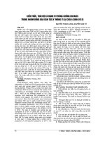
Maximum permissible bend of straight tubes
The maximum permissible bend 2) of straight tubes shall be as given in table 16.
The maximum permissible bend shall be applied to straight tubes with an outside diameter 6 mm or over up to and including 90 mm, and shall not be applied to tubes of
temper grades 0 and OL.
The maximum permissible bend for straight tubes having a length outside the specified range shall be subject to the agreement between the purchaser and the manufacturer.
Note
2)
The "bend" is defined as the depth of an arc over the reference length of
the tube, as shown in figure 1.
PROTECTED BY COPYRIGHT
20
H 3300 : 2012
Figure 1
Table 16
Bend of straight tube
Maximum permissible bend of straight tubes
Unit: mm
Division of length
Reference length
Maximum value
1 000 or over up to and incl. 2 000
Whole length
5
Over 2 000 up to and incl. 2 500
8
Over 2 500 up to and incl. 3 000
12
Over 3 000 up to and incl. 9 000
3000
12
7 Tests
7.1
a)
Sampling
The sampling of test shall be as follows.
Sampling for chemical analysis For the sample for analysis, an amount required
for analysis shall be taken at the time of casting.
Alternatively, analysis sample may be taken from an ingot or a product.
b)
For tensile test, hardness test, grain size test, flaring test, flattening test, electric conductivity test, hydrogen embrittlement test and season cracking test, test
piece shall be prepared from a tube drawn at random from each group consisting
of 100 tubes or tubes 2 000 kg in mass and its fraction, of the same grade, class,
temper grade and sectional dimensions.
c)
For hydraulic pressure test and pneumatic pressure test, the number of tubes
equivalent to 0.2 % of the total number of a group of tubes of the same grade, class,
temper grade and sectional dimension shall be drawn at random. However, for
tubes of C 4430, C 6870, C 6871, C 6872, C 7060, C 7100, C 7150 and C 7164, 100 %
testing shall be performed.
The tests may be performed on the tubes as processed, before giving them heat
treatment.
d)
7.2
The eddy current flaw detection shall be performed along the entire length of the
tube excluding the end dead zone.
Chemical analysis
The method of analysis of chemical composition shall be in accordance with the following standards:
PROTECTED BY COPYRIGHT