Jis g3202 2007
Bạn đang xem bản rút gọn của tài liệu. Xem và tải ngay bản đầy đủ của tài liệu tại đây (3.28 MB, 20 trang )
JIS
JAPANESE
INDUSTRIAL
STANDARD
Translated
Japanese
and
Published
Standards
by
Association
JIS G 33502
GISEF)
Hot-dip zinc-coated steel sheet and strip
ICS
77.140.50
Reference number : JIS G 3302 : 2007 (E)
PROTECTED
BY COPYRIGHT
215
G 3302 : 2007
Date of Establishment:
1951-10-31
Date of Revision:
2007-09-20
Date of Public Notice in Official Gazette:
2007-09-20
Investigated by: Japanese Industrial Standards Committee
Standards Board
Technical Committee on Iron and Steel
JIS G 3302 : 2007, First English edition published in 2007-12
Translated and published by: Japanese Standards Association
4-1-24, Akasaka, Minato-ku, Tokyo, 107-8440
JAPAN
In the event of any doubts arising as to the contents,
the original JIS is to be the final authority.
© JSA 2007
All rights reserved. Unless otherwise specified, no part of this publication may be reproduced or utilized
in any form or by any means, electronic or mechanical, including photocopying and microfilm, without
permission in writing from the publisher.
Printed in Japan
KK/HN
PROTECTED
BY COPYRIGHT
G 3302 : 2007
Contents
Page
Introduction
ere re rete r errr ere rere rete teeter ee rete rere re reece ete Terre rere Tree r ere Teer eee eee ee rere Terre rrr
1
Scope +2
9
'NöEBiHIVE?FGEEEGHBGRRIIDEIEENEREINRIEGEREHIRIISRRIIGIRBIIGIEGttRS@Sfftytaty
na 1
3
Grade, symbol and applicable nominal thicknegs -::+++++ttrrttttettthhttreeertteeeeree 5
4
Chremival composlinh >222+22teeeeeeiee0aeeeiih4
4e nen
H00 001.001400 Kong 3
5
Coating
5.1
5.2
5.3
Type of coating Coating mass
Coating surface finishes
5.4
Coating adherence
6
Ghemieal teeatnientT
7
Oiling-
8
Mechanical properties
8.1
Applicable mechanical properties
9
9.1.
9.2
Dimensions and tolerances
Expression of dimensions -Standard dimensions ---
9.3
Dimensional tolerances
10
10.1
10.2
10.3
Shapes -Camber Out-of-square
Flatness
A.
11.1
11.2
11.3
11.4
Mass and tolerances thereof
Mass of sheet
Mass of coil
Calculation method of mass
Tolerances on theoretical mass o0 sheet -'***r++rtttthhtttthtthhhetrrrrrreeerrrrrrrrerrer
12
Appearane -+:::::tttn nhu
8.2
8.3
HH
HH
Hit HH
kh
hờ
1
1
---:
aera
reroute
nen eenne wearers
Bendability
Tensile test characteristics
6
-
ie 17
Ác
13.1
Analysis test
13.2
18.3
Coating mass test
Corrosion resistance test of coating tiitttttterttttttttttr
ttt
tne 18
@)
“PROTECTED
BY COPYRIGHT
G 3302 : 2007
18.4
Methanieal teste
14
Inspection
--
14.1
14.2
Inspection
--
15
16
eerie
Re-inspection sr
Markings
Denne eee e
eran
iennerseison sen cmnnasoiiaeneemennraienceseeuuareaneniene 20
6 0 8.89 90608,8)8.8,8. 8:8
8 808 8,6 8,8 8:9 16 8,6 8.8.8.1 18 6:8 8,8,4,
Ttems to be confrmed at the tìme of order
17
18
ốốốốốốố
0006 8 8,88: 90109 008/8.8 8.8.0 0016.608 t6 20
--:+::++++rttttehhhhttththhhttetrteeeerree X4DT
ốc
22
Annex JA (normative)
Nominal thickness and coating mass symbol of sheet
and coil for roofing and architectural siding -:::::*++::+rrrr+++ 23
Annex JB (normative)
Nominal thickness, coating mass symbol and standard
Annex JC (normative)
Test method for coating mass of hot-dip zinc-coated
steel sheet and strip using fluorescent X-rays --::-::::::::++ 26
Annex JD (informative)
dimension for corrugated sheet
sitters
Comparison table between JIS and corresponding
International Standards
----::-:-:-------:+++++**rtttrtrrrhrrrrrret 98
Gi)
PROTECTED
24
BY COPYRIGHT
G 3302 : 2007
Foreword
This translation has been made based on the original Japanese Industrial Standard revised by the Minister of Economy, Trade and Industry
through deliberations at the Japanese Industrial Standards Committee
as result of proposal for revision of Japanese Industrial Standard submitted by The Japan Iron and Steel Federation (JISF) with the draft
being attached, based on the provision of Article
dustrial Standardization Law
provision of Article 14.
12 Clause
1 of the In-
applicable to the case of revision by the
Consequently JIS G 3302:2005 is replaced with this Standard.
This JIS document is protected by the Copyright Law.
Attention is drawn to the possibility that some parts of this Standard
may conflict with a patent right, application for a patent after opening
to the public, utility model right or application for registration of utility
model after opening to the public which have technical properties. The
relevant Minister and the Japanese Industrial Standards Committee
are not responsible
for identifying the patent
right, application for a
patent after opening to the public, utility model right or application for
registration of utility model after opening to the public which have the
said technical properties.
Gii)
=
PROTECTED
BY COPYRIGHT
JAPANESE
INDUSTRIAL STANDARD
JIS G 3302 : 2007
Hot-dip zinc-coated steel sheet and strip
Introduction
This Japanese
Industrial
Standard
has been prepared
based on the third edition of
ISO 3575 published in 2005 and the fourth edition of ISO 4998 published in 2005 with
some modifications of the technical contents.
The portions given sidelines or dotted underlines are the matters in which the contents of the corresponding International Standards
have been modified. A list of modi-
fications with the explanations is given in Annex JD. Furthermore, matters in Annex
JA to Annex JC are not stated in the corresponding International Standards.
1
Scope
This Standard specifies the steel sheet and strip (hereafter referred to as "sheet and
coil") equally zinc-coated on both surfaces in a bath of molten zinc containing 97 % or
over of zinc in mass fraction (provided that the aluminium
less). In this case, the
t:
heets
content is usually 0.30 % or
in flat fc
The International Standards corresponding to this Standard are as follows.
ISO
3575
: 2005
Continuous
hot-dip
ISO, 4998
: 2005
Continuous hot-dip zine-coated carbon steel sheet of
commercial and drawing qualities
structural quality
zinc-coated carbon
steel sheet
of
(Overall evaluation : MOD)
In addition, symbols which denote the degree of correspondence in the
contents between the relevant International Standards and JIS are IDT
(identical),
MOD
ISO/IEC Guide 21.
2
(modified),
and
NEQ
(not equivalent)
according
to
Normative references
The following standards contain provisions which, through reference in this text,
constitute provisions of this Standard. The most recent editions of the standards (including amendments) indicated below shall be applied.
£
PROTECTED
BY COPYRIGHT
2
G 3302 : 2007
ULE
JIS H 0401 Methods of test for hot dip galvanized coatings
NOTE:
Corresponding International Standard
: ISO
1460 Metallic coatings —
Hot dip galvanized coatings on ferrous materials —
mination of the mass per unit area (MOD)
3
a)
Gravimetric deter-
Grade, symbol and applicable nominal thickness Ð
The grade, symbol and applicable nominal thickness shall be as follows.
Note?
The nominal thickness refers to the base metal thickness before coating
The
and
sheet
[see 9.1 a)].
coil shall
be classified
strips (hereafter referred to as
and their grade
symbols
and
into
6 grad
‘ing he
nd
"hot-rolled base metal") and into 11 grades using
applicable
nominal
thicknesses
shall be as given in
table 1 and table 2.
b)
For the sheet and coil used for roofing and architectural siding, the symbol R indithe grade symbol in table 2. In this case.
&.
the applicable nominal thickness and th:
©
sheet. shall be suffixed to the grade symbol in table 2 (for roofing or architectural
oating mass symbol shall be
in accordance
PROTECTED
with Annex
BY COPYRIGHT
3
G 3302 : 2007
Table 1
Grade symbol and applicable nominal thickness
[using hot-rolled base metal ®]
Grade symbol | _Applicable nominal thickness
SGHC
1.6 or over up to and incl. 6.0
SGH340
SGH400
Commercial use
Structural use
Application
Unit : mm
SGH440
SGH490
SGH540
Note”
For the nominal thickness of 1.6 mm or over up to and including 3.2 mm, unless the
hot-rolled base metal is particularly specified, the cold-reduced base metal which
satisfies the specification of the hot-rolled base metal may be used.
Table 2
Grade symbol and applicable nominal thickness
(using cold-reduced base metal)
Grade symbol | Applicable nominal thickness ®
Application
SGCC
0.25 or over up to and incl. 3.2
| Commercial use
SGCD1
0.40 or over up to and incl. 2.3
| Drawing use Class 1
0.60 or over up to and incl. 2.3
Drawing use Class 3
SGCH
SGCD2
SGCD3
SGCD4
SGC340
SGC400
SGC440
SGC490
0.11 or over up to and incl. 1.0
Unit : mm
Commercial use of hard class
Drawing use Class 2
Drawing use Class 4, non-aging property »
0.25 or over up to and incl. 3.2
Structural use
SGC570
0.25 or over up to and incl. 2.0
For the corrugated sheet, the grade of commercial use, commercial use of hard class and
structural use in this table shall be used.
Notes © The nominal thickness other than those listed in this table may be applied upon the
»)
4
agreement between the purchaser and the supplier.
The non-aging property refers to the property free from the stretcher strain during
working.
Chemical composition
For the chemical composition
of the base
metal
of sheet and
coil, the test shall be
performed in accordance with 18.1 and the heat analysis values shall be as given in table 3.
PROTECTED
BY COP¥RIGHT-.......--..
ie
4
G 3302 : 2007
Table 3
Grade symbol
Cc
Mn
max.
max.
max.
max.
0.80
1.70
1.70
2.00
P
SGH540
0.30 max.
2.50 max.
0.20 max.
0.05 max.
SGCH
SGCD1
0.18 max.
0.12 max.
1.20 max.
0.60 max.
0.08 max.
0.04 max.
0.05 max.
0.04 max.
SGCD4
SGC340
0.06 max.
0.25 max.
0.45 max.
1.70 max.
0.03 max.
0.20 max.
0.03 max.
0.05 max.
SGC440
0.25 max.
2.00 max.
0.20 max.
0.05 max.
0.30 max.
2.50 max.
SGCC
2.00 max.
0.15 max.
SGCD2
SGCD3
0.80 max.
0.10 max.
0.08 max.
SGC400
0.45 max.
0.45 max.
0.25 max.
SGC490
1.70 max.
0.30 max.
SGC570
2.00 max.
0.05
0.20
0.20
0.20
Ss
0.15
0.25
0.25
0.25
0.30 max.
max.
max.
max.
max.
max.
max.
max.
max.
0.20 max.
0.05 max.
0.03 max.
0.03 max.
0.20 max.
0.20 max.
0.20 max.
0.05
0.05
0.05
0.05
Unit + %
SGHC
SGH340
SGH400
SGH440
SGH490
ð
Chemical composition
max.
max.
max.
max.
0.05 max.
0.05 max.
0.03 max.
0.03 max.
0.05 max.
0.05 max.
0.05 max.
Coating
ð.1
Type of coating
The coating shall be classified into two types: non-alloyed coating and alloyed coating ”.
Note ?)
The alloyed coating refers to the coating obtained in such a way that an
alloyed layer of iron and zinc is produced in the entire coating layer by
heating after coating.
5.2
Coating mass
5.2.1
Coating mass symbol
For coating, both surfaces shall be equally coated in thickness, and the coating mass
symbol shall be as given in table 4.
5.2.2
Coating mass
For the coating mass, the test shall be performed in accordance with 13.2, and the
minimum coating mass shall be as follows. The maximum coating mass
both surfaces) may be agreed between the purchaser and the supplier.
a)
(total mass on
The coating mass on the sheet and coil shall be expressed by the total mass on both
surfaces, and the minimum average coating mass at triple spots and the minimum
coating mass at a single spot shall be as given in table 4. Here, the minimum
erage coating mass
at triple spots shall apply to the average of the measured
avval-
ues of the coating masses of three test pieces cut from the specimen, and the
minimum coating mass at a single spot shall apply to the smallest of the measured
values of the coating masses of the three test pieces of which the average value is
obtained.
PROTECTED
BY COPYRIGHT
5
G 3302 : 2007
Table 4
Type of coating
Minimum coating mass (total mass on both surfaces)
Coating mass symbol | Minimum average
Non-alloyed coating
Minimum coating
coating mass at triple | mass at single spot
spots
Z06 »
60
51
Z08
Z10
Z12
Z14
Z18
Z20
222
Z25
227
Z35
Z37
80
100
120
140
180
200
220
250
275
350
370
68
85
102
119
153
170
187
213
234
298
315
Z60
600
510
06
F08
60
80
51
68
Z45
Alloyed coating
Unit : g/m?
450
F04 ®
383
40
F10
34
100
85
F12
120
102
F18”
180
153
The coating masses corresponding to Z35, Z37, Z45, Z60, F10, F12 and F18 shall not apply to
SGCD1, SGCD2, SGCD3 and SGCD4.
Note ®
b)
Applicable only when agreed between the purchaser and the supplier.
The minimum
coating mass at a single spot on either surface on the sheet and coil
should be 40 % or over of the minimum
both surfaces).
5.3
coating mass at a single spot (total mass on
Coating surface finishes
5.3.1
Type and symbol of surface finish for non-alloyed coating
The type and the symbol of the coating surface finish shall be as given in table 5.
Table 5
Type and symbol of surface finish for non-alloyed coating
Type of coating surface finish | Symbol
Regular spangle
Minimized spangle
5.3.2
Remarks
R
A coating having
Z
cation.
A coating having the spangles obtained by restricting
stricted growth
spangles
as a result of the unre-
of zinc crystals during normal
solidifi-
normal spangle formation to a minimum.
Skin-pass
Skin-passing to obtain surface smoothness shall be in accordance with the designa-
PROTECTED BY COPYRIGHT
6
G 3302 : 2007
tion by the purchaser. In this case, the symbol shall be 8.
5.4
Coating adherence
For the coating adherence of the flat sheet and coil to which the non-alloyed coating
is applied, when the test is performed in accordance with 18.4.2 under the bend test
condition given in table 9 or table 10, there shall be no flaking of the coating on the
outside of the bent portion (within an area 7 mm or over from each side of the test
piece).
In
addition,
the.co
6
Chemical treatment
The type and the symbol of the chemical treatment for the flat sheet and coil shall be
as given in table 6. Unless otherwise specified, the non-alloyed coating shall be subjected to the chromate treatment or chromate-free treatment, and the alloyed coating
shall be untreated.
Chemical treatments other than those in table 6 may be agreed upon between the
purchaser and the supplier.
Table 6
Type and symbol of chemical treatment
Type of chemical treatment.
Symbol
Chromate treatment
Cc
Phosphate treatment ®
£
Chromate-free treatment »)
NC
NP
Untreated
©__
7
M
Chromate:free phosphate treatment refers to the chemical treat:
the.
Oiling
The type and the symbol of oiling for the sheet and coil shall be as given in table 7.
Unless otherwise specified, the non-alloyed coating shall be unoiled and the alloyed
coating shall be oiled.
PROTECTED
BY COPYRIGHT
7
G 3302 : 2007
Table 7
Type and symbol of oiling
Type of oiling
Symbol
Oiled
0
Unoiled
8
X
Mechanical properties
8.1
Applicable mechanical properties
Applicable mechanical properties for the flat sheet and coil shall be as given in table 8.
SGH490
SGH540
| JâlololOlâ
SGH440
e
'âlOlOlClCâlOlOlO|ClN
SGHC
SGH340
SGH400
Bendabilityđ | Tensile test
characteristics ằ
|O|Cl|OlOlOlOlOlI
Grade symbol
Applicable mechanical property
[ |âlCâlOlOâlOlOâlOlO|I
Table 8
SGCC
SGCH
SGCD1
SGCD2
SGCD3
SGCD4
SGC340
SGC400
SGC440
SGC490
SGC570
Notes đ Apply to the non-alloyed coating and not apply
ằ)
â
đ
â
8.2
to the alloyed coating.
For the nominal thickness under 0.25 mm, the
tensile test shall not apply.
When used for corrugated sheets, the bend-
ability shall not apply.
The bendability shall not apply.
The tensile test characteristics shall not apply.
Bendability
For the bendability of the flat sheet and coil to which the non-alloyed coating is applied, when the test is performed in accordance with 13.4.2 under the bend test condition given in table 9 and table 10, there shall be no cracking (visible to the naked eye)
or fracture of the base metal on the outside of the bent portion (within an area 7 mm
over from each side of the test piece).
NOTE:
For the performance of the bend test, see 13.4.2.
PROTECTED
BY COPYRIGHT
or
8
G 3302 : 2007
Table 9
Grade
symbol
Bending
angle
Internal spacing of bend (number of sheets of nominal thickness)
Nominal thickness
Nominal thickness
1.6 mm
SGH440
SGH490
Z35,Z37 |
1
180
°
SGH540
Grade
symbol
or over to and excl. 3.0 mm
|Bending
angle
SGCD2
0 (Flat
1
180°
2
2
245, Z60
2
1
2
1
2
2
2
2
3
2
3
3
3
3
3
3
3
3
3
Under 1.6 mm
SGCC
SGCD4 |
Z06 to Z27 | _ 235, 237
2
Table 10 Bendability (2)
Internal spacing of bend (number of sheets of nominal thickness)
Nominal thickness
Nominal thickness
Nominal thickness
Z06 to
227
1
SGCD3
or over
Coating mass symbol
Z45, Z60_|
2
Coating mass symbol
SGCD1
3.0 mm
Coating mass symbol
Z06 to Z27 |
SGHC
SGH340
SGH400
Bendability (1)
on it-
|self)
|Z35,
Z37
245,
Z60
1
2
—
—
—
—_
1.6 mm or over to and
excl. 3.0 mm
Coating mass symbol
Z06 to
Z27
1
symbol
—
—
2
|onit-
=
—
a
=
=
0 (Flat
self)
245,
260.
Coating mass
Z06 to
227
2
1
|Z35,
Z37
2
3.0 mm or over
—
|Z35,
Z37
2
245,
Z60.
—
—
2
SGC340
SGC400
1
2
1
2
2
2
dL,
2
1,
2
2
2
2
3
2
3
3
3
SGG490
3
3
3
3
3
3
3
3
3
SGC440
8.3
ä
Tensile test characteristics
For the tensile test characteristics of the flat sheet and coil, when the test is performed in accordance with 13.4.3, the result shall be as given in table 11 or table 12.
The yield point shall be the upper yield point.
PROTECTED
BY COPYRIGHT
9
G 3302 : 2007
Table 11
Grade
Yield
symbol
Elongation
Tensile
|point or
%
|strength
Nominal thickness
pron
stress
N/mm?
SGHC_
Tensile test characteristics (1)
N/mm?
direction of
16or
|30or
|2.50r
|32or
|4.00r
over to
and
|overto
and
|overto
and
|overto
and
|overup
to and
excl. 2.0
|@05min)| @70mn)|
ee
Test piete and
— |
|excl. 2.5
— |
|excl. 3.2
— |
|r oncite test
|exel. 4.0 incl. 6.0
—
¬-`
~
SGH340 | 245 min. |
SGH400 | 295 min. |
340 min. | 20 min. | 20 min. | 20 min. | 20 min. | 20 min.
400 min.
7
si
ặ
š
„
|No. 5 in rolling
|direction or
SGH490 |
365 min. |
490 min.
|to the rolling
NOTE 1
NOTE 2
1N/mm?=1 MPa
Values in parentheses are shown for reference.
SGH440 | 335 min. | 440 mịn, | TỔ TÔI, | 18 min, | 1ổ mẫn, | 18 mắn, | lỗ mắn. |, ybandieular
‘SGH5401
400 min. |
+
540 min.
Table 12
Grade
rage)
|Yield
[Mis
symbol
2
Nimm? | Nimm?
SGCC
.
._
Elongation
|strength
f
.
Tensile test characteristics (2)
{Tensil
peels
|point or
oe
vs
16 min. | 16 min. | 16 min. | 16 min. | 16 min. | gi oction
2
|@05min.|@70min)|
26thickness
Nominalan
025 or [O40 or ]0.60or
|LOor
|léor
overto
|overto
|overto
Voxel.
excl.
_excl. 1.0 |exel.1.6 |exel.3.5
Jand
0.40
—
and
0.60
and
|overto
ir ent
and
|overto
and
=
—
—
—
=
=
=
z=
[250r
|over
id. di[roan
lof ten-
ĩ
sile test
=
(ee
_—--|direetion
SGCH®
—
—
4
SGCD1
a
270 min.
=
34 min. | 36 min. | 37 min. | 38 min.
5
SGCD2
—
270 min.
—
36 min. | 38 min. | 39 min. | 40 min.
—
SGCD3
—
270 min.
—
38 min. | 40 min. | 41 min. | 42 min.
—
SGCD4Đ
—
270 min.
—
| 40 min. | 42 min. | 43 min. | 44 min.
—
SGC340.
piece
|245 min. | 340 min. | 20 min. | 20 min. | 20 min. | 20 min. | 20 min. | 20 min.
ee
$GC400 | 295 min. | 400 min. | 18 min. | 18 min. | 18 min. | 18 min. | 18 min. | 18 min. aoe
SGC440 | 335 min. | 440 min. | 18 min. | 18 min. | 18 min. | 18 min. | 18 min. | 18 min. La
cular
SGC490 | 365 min. | 490 min. | 16 min. | 16 min. | 16 min. | 16 min, | 16 min. | 16 min. ea the
rolling
SGC570 | 560 min.} 570 min.|
NOTE
NOTE2
Notes
»)
1
—
—
—
—
—
—
|direetion
Values in parentheses are shown for reference.
1N/mm?=1MPa
SGCH is a material not subjected to annealing, usually having a Rockwell hardness
of 85 HRB or more or a Vickers hardness of 170 HV or more (the test load may be
chosen appropriately).
For the sheet and coil of SGCD4, the stretcher strain shall not be generated when
working is performed during six months after manufacturing.
PROTECTED
BY COPYRIGHT
10
G 3302 : 2007
9
Dimensions and tolerances
9.1
Expression of dimensions
The dimensions of sheet and coil shall be expressed as follows.
a)
For the thickness of sheet and coil, the thickness of the base metal prior to coating
shall be regarded as the nominal thickness and the thickness of the base metal after coating shall be regarded as the product thickness.
Table 13
(0.27)
1.6
(0.30)
Ray
(0.35)
2.0 PY
0.40
Standard nominal thickness
Standard nominal thickness
0.50.
2.8
0.60
0/70
3.2
36
.0.8040
Unit : mm
0.90
45
«1,0
1.2,
5.0
5,6
14
6.0
Values in parentheses shall apply to the coating mass or more coatings corresponding to
the non-alloyed Z18. Upon the agreement between the purchaser and the supplier, the
thicknesses of 0.65 mm and 0.75 mm may serve as the standard nominal thicknesses.
b)
Standard width and standard length of sheet The standard width of sheet and
coil, and the standard length of sheet shall be as given in table 14.
Table 14
Standard width and standard length of sheet
Unit: mm
Standard width
762
914
1 000
1219
1524
1829
1829
2 000
2438
3048
1829
3 658
As for the coil, 610 mm
2134
2134
Standard length of sheet
2438
2743
3048
3353
2438
2743
3048
3353
3048
3658
3658
3658
shall also be regarded as the standard width in
addition to those given in this table.
PROTECTED
BY: COPYRIGHT
3:2) 0 ots
11
G 3302 : 2007
9.3
Dimensional tolerances
9.3.1
Tolerances on product thickness
Tolerances on the product thickness of sheet and coil shall be as follows.
a)
ly
to the value of the nominal thickQU
b)
Tolerances on the product thickness shall be as given in table 15, table 16 or table
17
o)
The product thickness shall be measured at any point 25 mm or over from the side
da)
Shall not apply to the irregular portions such as the welds in a coil.
edge (the end in the width direction) .
Table 15
Tolerances on product thickness (applicable to SGHC)
Unit: mm
Width
Nominal width
1900 or over to|1 500 or over to|1 800 or over up.
Under 1 200_|and excl. 1 500 | and exel. 1 800 |to and inel. 2 300
1.60 or over to and excl. 2.00
+ 0.17
+0.18
+0.19
‡ 0.22 9)
2.50 or over to and excl. 3.15
+ 0.20
+ 0.22
£0.25
+£0.27
+0.30
+0.3L
=z
=
2.00 or over to and exel. 2.50
3.15 or over to and excl. 4.00
4.00 or over to and excl. 5.00
5.00 or over to and excl. 6.00
6.00
Note»
+0.18
+ 0.20
+ 0.22
+ 0.25
+ 0.27.
+ 0.24
+0.27
+ 0.29
+ 0.22
+ 0.27
=
—
Applicable to those of width under 2 000 mm.
Table 16
+ 0.26 ®)
+0.28
—
—
Tolerances on product thickness (applicable to SGH340,
SGH400, SGH440, SGH490 and SGH540)
.
:
Nominal width
1.60 or over to and excl. 2.00
Unit: mm
Width
Under 1 600 | 1 600 or over to and excl. 2 000
2.00 or over to and excl. 2.50
2.50 or over to and excl. 3.15
3.15 or over to and excl. 4.00
4.00 or over to and excl. 5.00
5.00 or over up to and incl. 6.00
PROTECTED
+0.20
+ 0.24
£0.23
+ 0.30,
£0.46
=
£0.21
+ 0.25
+0.51
BY COPYRIGHT
+£0.26
+ 0.35
—
12
G 3302 : 2007
Table 17
Tolerances on product thickness (applicable to SGCC,
SGCH, SGCD1 to SGCD4 and SGC340 to SGC570)
Unit ‘mm
Nominal
630 or over to
thickness
—
Under 630___|and excl. 1000
Under 0.25
0.35 or over to
+ 0.04
-
nh
and excl. 0.60
0.60 or over to
and excl. 0.80
tên
£0.07
0.80 or over to
|and exel. 1 600,
—
—
+ 0.05
£0.05
+ 0.06
—
Hà
St
+0.07
+ 0.04
—
-
oor
+006
£008
£0108
0.40 or over to
1 600 or over
|and excel. 1 250
+ 0.04
£0.05
and excl. 0.40
Width
}1 000 or over to} 1 250 or over to|
xong
+0:
+0.
£0.07
£0.07
+0.08
vẽ
and excl. 1.00
£0.07
£0.07
+ 0.08
+£0.09
+0.10
and excl. 1.25
+ 0.08
+0.08
£0.09
£0.10
£0.12
and excl. 1.60
+ 0.09
£0.10
+011
£0.12
+0.14
and excl. 2.00
2.00 or over to
£0.11
£0.12
£0.13
£0.14
+0.16
z018
£0.14
£0.15
£0.16
£0.18
+0.16
£0.18
+0.17
£0.20
£0.18
£0.21
+0.31
—
1.00 or over to
1.25 or over to
1.60 or over to
and exel, 2.50
2.50 or over to
and exel. 3.15
3.15 or over
+0.15
£0.17
-
Table 18
l
—
Equivalent coating thickness
Non-alloyed coating
Coating
mass
symbol
Unit : mm
| 756 | zoe | zio | z12 | zi | Z18 | 220 | 292 | 225 | 227 | 235 | 237 | 245 | 26
Equivalent
:
0.013]0.017}0.021]0.026]0.029]0.034] 0.040] 0.043]0.049]0.054|0.064/0.067] 0.080) 0.102.
coating thickness
Alloyed coating
Coating mass
symbol
Equivalent
ụ
+
coating thickness!
9.3.2
F04
T06
0.008 |
F08
0.013 |
0.017 |
E10
0.021 |
F12
0.026 |
F18
0.034
Tolerances on width
Tolerances on the width of sheet and coil shall be as given in table 19. Width shall be
measured
at a normal
portion in a coil and at any position for sheet.
PROTECTED
BY COPYRIGHT
However, toler-
18
G 3302 : 2007
Table 19
Tolerances on width
Unit : mm
Applicable grade symbol
SGHC, SGH340, SGH400, SGH440,
SGCC, SGCH,
SGH490, SGH540
SGCD1 to SGCD4,
Tolerance A®
Tolerance B®
SGC340 to SGC570
Width
1500 or under
+25
+10
0
+7
0
0
Over 1 500
Note®
9.3.38
+10
0
Generally, tolerance A is applied to the mill edge and tolerance B is applied
to the cut edge.
Tolerances on length
Tolerances
on the length of sheet shall be as given in table 20. The length shall be
measured at any position of sheet.
Table 20
Tolerances on length
Unit: mm
Tolerances on length
+15
0
10
Shapes
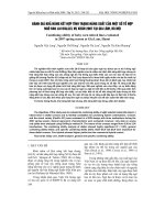
10.1
Camber
The application of camber for the flat sheet and coil shall be as shown in figure 1.
The maximum
camber of the flat sheet and coil shall be as given in table 21 or table 22.
However, the camber shall not apply to the irregular portions in a coil. The measurechaser,
the misdsurerment, shall be performed.
Note
®
The measurement of camber may be omitted by the judgment of the
manufacturer on the precondition that camber shall satisfy the specified
value.
Camber
[7
Camber
Mon
L
For flat sheet of SGHC to
SGH540 and flat sheet of SGCC
to SGC570 under 2 000 mm in
length
Width
2000
Arbitrary position
For flat sheet of SGCC to
SGC570 at least 2 000 mm in
length
Figure 1
Application of camber
PROTECTED
BY COPYRIGHT
Camber
2000
Unit ‘mm
Arbitrary position
For coil
Width
14
G 3302 : 2007
Table 21
Maximum value of camber (applicable for SGHC,
SGH340, SGH400, SGH440, SGH490 and SGH540)
Unit mm
Flat sheet
Length
Width
Under 2 500 | 2.500 or over | 4000 or over
Under 630
5
1.000 or over
3
630 or over to and excl. 1 000
Table 22
to and excl.
4 000
4
8
12
5
8
6
Coil
a
10
ee 2000
Maximum value of camber (applicable for SGCC SGCH,
SGCD1 to SGCD4 and SGC340 to SGC570)
Unit : mm
Flat sheet
Width
Length
Under 2 000
Under 630
4
630 or over
10.2
Coil
2.000 or over
4in any 2 000 length
2
2in any
2 000 length
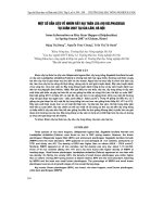
Out-of-square
The out-of-square for the flat sheet shall be expressed as
Ẵ
x 100 (%) in figure 2
and shall not exceed 1 %.
b (width)
"—
11...
i
Figure 2
10.3
Out-of-square for flat sheet
Flatness
The flatness for the flat sheet shall be as given in table 23 or table 24. The flatness
shall be measured with a sheet lying under its own mass on a flat surface, and the
value of flatness shall be obtained by subtracting the product thickness from the maximum deviation from the flat horizontal surface. The value thus obtained shall apply to
the upper surface of the sheet.
PROTECTED
BY COPYRIGHT
lỗ
G 3302 : 2007
Table 23
Flatness for flat sheet (applicable for SGHC,
SGH400, SGH440, SGH490 and SGH540)
Nominal thickness
Under 1 250
1.60 or over to and excl. 3.15
3.15 or over to and excl. 4.00
16 max.
Unit ‘mm
Width
|1 250 or over to |1 600 or over to }2 000 or over up
and excl. 1 600_|and excl. 2 000_|to and incl. 2 300
18 max.
16 max.
4.00 or over to and excl. 6.00
6.00
Table 24
SGH340,
20 max.
=
=
14 max.
13 max.
24 max.
21 max.
Flatness for flat sheet (applicable for SGCC, SGCH,
SGCD1 to SGCD4 and SGC340 to SGC570)
Unit : mm
.
Under 1.000
ko
Bow
12 max.
Type
Edge wave
8 max.
Centre buckle»
6 max.
1.000 or over to and excl. 1 250
15 max.
9 max.
8 max.
1 250 or over to and excl. 1 600
15 max.
11 max.
8 max.
1.600 or over
20 max.
13 max.
9 max.
Notes®
It refers to the type of flatness in which a corrugation appears at the edge (the end
©
11
in the width direction) of flat sheet.
Ttrefers to the type of flatness in which a corrugation appears at the central part of flat sheet.
Mass and tolerances thereof
11.1
Mass of sheet
The mass of sheet shall usually be given in the theoretical mass in kilogrammes.
11.2
Mass of coil
The mass of coil shall be given in either the actual or the theoretical mass in kilogrammes.
11.3
Calculation method of mass
The calculation method of the mass of sheet and coil shall be as given in table 25.
PROTECTED
BY COPYRIGHT