Iso 6892 1 16
Bạn đang xem bản rút gọn của tài liệu. Xem và tải ngay bản đầy đủ của tài liệu tại đây (515.81 KB, 5 trang )
ISO 6892-1:2016
Ambient Tensile Testing of Metallic Materials
What Changed?
In 2009, ISO 6892-1 replaced and combined both the
previous ISO 6892 and the widely used EN10002-1:2001
standards. It incorporated many changes, but most notably,
it introduced the testing rates based on strain rate (Method
A).
the specimen faster. On the less stiff (more compliant)
system, the strain rate was 21% lower and took longer to
transfer to the specimen. This meant there was a 5%
difference in the yield result for this material on these two
different systems.
Method A was the recommended approach and was based
on maintaining a strain rate. The traditional test method
from EN10002:2001, based on maintaining a stress rate
during the elastic region, became Method B. The
introduction of Method A caused confusion. Many
understood this as only being achievable using equipment
capable of closed-loop strain control, but this is not true. It is
possible to conform to Method A using a constant crosshead
speed.
To better clarify, the requirements of Method A, ISO 68921:2016 now includes two clearly defined approaches,
Method A1 (Closed-Loop Strain Control) and Method A2
(Constant Crosshead Separation Rate).
Since Method A is the recommended test method, this
further clarification will assist test labs that are transitioning
from Method B to Method A and monitoring the specimen
strain rate. The benefits remain the same: Method A
minimizes the variation of the test rates during the moment
when strain-rate sensitive parameters are determined and
to minimize the measurement uncertainty of the test results.
During a tensile test there are many sources for uncertainty
and error; maintaining the strain rate on the specimen
eliminates
the
effect
that
the
machine's
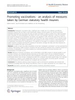
stiffness/compliance has on the results. Figure 1 shows the
difference in yield results run at the same machine
crosshead separation rate: the upper (red) stress/strain
curve was tested on a high stiffness testing machine and the
lower (orange) stress/strain curve was on a less stiff (more
compliant) testing machine. Both systems were controlled at
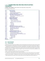
a constant crosshead speed of 2.25 mm/min. Figure 2
shows the specimen ‘speed’ expressed in mm/min. On the
stiffer system, the strain rate was higher and transferred to
Figure 1 Testing Machine Stiffness Comparison – Two tests are carried out using the
same material but on two different machines at the same crosshead speed.
Figure 2 Testing Machine Stiffness Comparison – Specimen speed (or strain rate)
expressed in mm/min can be seen to be considerably lower than the machine speed
of 2.25 mm/min. ‘Speed’ is lost in the compliance of the testing machine setup.
www.instron.com | Page 1 of 5
Switching from Method B towards Method A will make
results much more comparable between sites, as well as
between different machines. Method A2 may increase
testing times slightly (when compared to method B), so the
additional benefit from utilizing Method A1 is that test times
can be reduced by up to 40% per test. This will vary from
machine and specimen type, but you may see significant
reduction in test times, which will help to increase laboratory
efficiency.
Method A1 & A2 Rates
The defined rates in ISO 6892:2016 are the same as
Method A in ISO 6892-1:2009, which are dependent on the
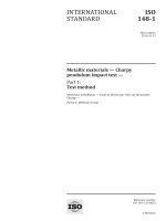
results that are being determined. Figure 3 shows how the
ranges are defined from ISO 6892-1. Range 2 is the
recommended rate for determining yield (Rp) and Range 4 is
recommended for determining Rm, Agt, Ag, At & A. Figure 4
shows where these calculations are determined and where
the ranges would be.
Method A1 closed-loop control of the strain rate based on
feedback from the extensometer, with a ‘tight’ ±20%
tolerance.
Method A2 ‘open-loop’ constant crosshead speed (obtained
by multiplying the required strain rate by the parallel length).
𝐶𝑟𝑜𝑠𝑠ℎ𝑒𝑎𝑑 𝑆𝑝𝑒𝑒𝑑 = 𝑆𝑡𝑟𝑎𝑖𝑛 𝑅𝑎𝑡𝑒 𝑥 𝑃𝑎𝑟𝑎𝑙𝑙𝑒𝑙 𝐿𝑒𝑛𝑔𝑡ℎ
This calculation does NOT take into account the effect of the
testing machine compliance. As can be seen in Figure 2,
some of the strain rate will be ‘lost’ in the system. Annex F
from ISO 6892:2016 gives additional guidance for the
‘Estimation of the crosshead separation rate in
consideration of the stiffness (or compliance) of the testing
equipment)’.
Range 1: 0.00007s-1 ± 20%
Range 2: 0.00025s-1 ± 20% (Recommended)
Range 3: 0.002s-1 ± 20%
Range 4: 0.0067s-1 ± 20% (Recommended)
Figure 3: ISO 6892-1:2016 Rates
Figure 4: ISO 6892-1:2016 Method A Rates – Expressed graphically in comparison with the required results
www.instron.com | Page 2 of 5
Method A1 – Strain ControlA
For metals that demonstrate a smooth transition from the
elastic to plastic region, the strain distribution in the gauge
length of the material is uniform through the offset yield (Rp)
and up to the maximum tensile stress (Rm). In this case,
strain control can be achieved using the signal from the
extensometer. The challenge with controlling from feedback
from the extensometer is that tuning is required, (typically for
the ‘PID’ gain settings) because the control loop is affected
by the specimen stiffness. This can be time consuming and
requires skilled operators. Tuning may need to be performed
for each material tested with adjustments being made
between tests of different materials. If tuned for the elastic
region, the stiffness change in the specimen when it yields
may adversely affect the control and allow the strain rate to
go out of the ±20% tolerance. Every aspect of the testing
system will affect the suitability for strain control including
testing machine stiffness, load cell stiffness, as well as the
specimen gripping mechanics.
Strain control is not suitable for metals that display yield
point elongation (YPE/Ae) as the strain distribution along the
parallel length is no longer uniform. Instead, it is localized in
narrow regions known as Luders bands, which often occur
outside of the extensometer gauge length. When this
happens, strain measured by an extensometer can actually
decrease despite strain over the entire parallel section of the
specimen is increasing.
types. The system compliance means the strain rate
decreases, not increases. Therefore, if you use a rate higher
than the target rate, but still within the ±20% tolerance, it is
likely to be compliant. In other words, you may comply to the
standard if you calculate based on 0.0003 mm/mm/s (high
limit of ±20% tolerance) to achieve 0.00025 mm/mm/s
±20%.
Benefits of Using Strain Control
✓ More repeatable and comparable results; test results
reliable from machine to machine
✓ Improved efficiency; time per test minimized and setup
time reduced
✓ Future proofing your laboratory
✓ Less operator training when using 5900 automatic gain
tuning
Considerations to Using Strain
Control
May need to use specimens to tune gain settings
Minimizing compliance in the testing machine configuration
will help achieve closed-loop strain control
High-precision extensometer is required
Method A2 – Crosshead Control
Method A2 is suitable for all material types, and most
machine configurations are capable of performing a closed
loop constant crosshead speed. Therefore, it is much
simpler to install and run in your lab, especially when using
older equipment without a current upgrade. However, going
at a constant crosshead speed typically makes the test
slower. To assist with this, ISO 6892-1:2016 allows you to
test at any suitable speed up to 50% of yield strength (Rp)
because, in the elastic region, metals are typically not as
strain-rate sensitive.
The exact crosshead speed necessary to stay within the
±20% tolerance may be different for each material type and
for different cross sections. In order to stay compliant you
may need to fine tune the speed when you change specimen
Lab environment must be free of vibration or the test system
is isolated so that it can’t be transmitted to the specimen
Requires a responsive controller with high data collection
rate and loop update rate response rate
A proportional specimen and a proportional gauge length
extensometer are ideal. In reality, a specimen with good
gauge length to parallel length ratio is well suited to minimize
the strain seen outside of the gauge length, allowing the
control to be more stable.
If your specimens vary from discontinuous yielding to
continuous yielding, it is important to change control
methods for each type. Discontinuous yielding materials
must be in crosshead speed control during YPE.
www.instron.com | Page 3 of 5
Instron Solution
Instron testing machines are able to meet the demanding
requirements of ISO 6892-1:2016: Method A1, based on
strain rate control, Method A2 based on constant crosshead
speed, and Method B based on stress rate.
Materials Testing Machines
Our electromechanical or static-hydraulic machines can be
equipped with a range of clip-on or high-resolution automatic
extensometers for strain rate control. With many gripping
solutions available, Instron has a suitable gripping
mechanism for almost all material types. Advanced 5900
digital control electronics provide a 5 kHz loop update rate
and self-adaptive strain control ensuring stable and accurate
strain control under a wide range of conditions.
typical calculations for ISO 6892-1 have been determined,
including ReH and ReL.
A discontinuously yielding material elastically deforms up
until ReH. Following ReH the force typically drops dramatically
as the strain continues to increase. In addition, local yielding
can occur outside the extensometer gauge length. If the
testing machine remained in strain control, the testing speed
would change dramatically to counter this yielding
characteristic resulting in an incorrect strain rate and noncompliance with the standard. Using an intelligent algorithm,
the Instron machine swaps to position control, as detailed in
the standard, allowing it to maintain the standard defined
estimated strain rate through the discontinuous yielding
region. At the end of this yielding region with the onset of
strain hardening the machine then moves to a final rate that
it maintains until the conclusion of the test.
Method A1
Materials with no Yield Point
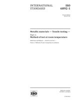
Figure 5 shows a typical test curve of a specimen that
exhibits no distinct yield point. This is known as continuously
yielding behavior. Construction lines show points where
typical calculations for ISO 6892-1 have been determined,
including Rp0.2 and Rm. Construction lines or markers are
available for almost all calculations in Bluehill® 3 for a quick
and easy visual indication of the correct result being
calculated.
Figure 5: Bluehill 3 Stress/Strain graph with additional y-axis for strain rate plotted,
with ±20% tolerance indicated
ISO 6892-1 details test speeds that must be adhered to
within a tolerance of ±20% while certain material properties
are calculated. There are four speed ranges in total, with
recommendations as to which should be used at each point
of the test. Figure 5 focuses on the yield region of the test
curve. The orange line show the strain rate being maintained
well within the ±20% allowable limits (tolerance indicated by
red dotted line).
Materials with Distinct Yield Point
Figure 6 shows a typical curve for a specimen that exhibits
abrupt yield point behavior. This is known as discontinuously
yielding behavior. Construction lines show points where
Figure 6: Bluehill 3 Stress/Strain graph of discontinuously yielding material.
www.instron.com | Page 4 of 5
Method B – Stress Control
The defined rates in ISO6892-1:2016 are as shown in Figure
7 and remain the same as Method B from ISO 6892:1:2009,
and include two allowable ranges based on the modulus of
elasticity of materials.
Figure 7: ISO 6892-1:2016 Method B Rates
The primary change for Method B in ISO 6892-1:2016 is the
addition of a note addressing the region of the test where
Method B or the stress rate shall be maintained. It is NOT
intended to maintain a stress rate for determining yield
parameters. As a material yields the ‘stress rate’ will drop or
even go negative (with discontinuously yielding material).
Maintaining a stress rate in closed-loop control stress or load
control will cause the machine to accelerate rapidly during
yielding. This is NOT compliant to ISO6892-1 and can result
in giving higher yield strengths and much shorter test times.
It may even cause the upper yield point to be hidden for
discontinuous yielding materials.
When using testing machines capable of closed-loop
load/stress control the stress rate should be achieved in the
elastic region and then switched before 80% of expected
Rp0.2 to maintain a constant crosshead speed. During the
elastic region of a metals test the load should be
proportional. Once in stable, closed-loop stress control a
constant crosshead will achieve the stress rate throughout
the rest of the elastic region and be suitable for yield
determination.
Figure 8: Region of stress control on continuous and discontinuously yielding
material.
References
International Organization for Standardization, Metallic
materials -- Tensile Testing -- Part 1: Method of test at room
temperature, ISO 6892-1:2009, International Organization
for Standardization, Geneva.
Disclaimer
This document has been prepared in accordance to the
international testing standard at the date of issue. This
document combines the standards, together with Instron’s
application knowledge. Should there be any errors or any
changes in the standard this is not the responsibility of
Instron. However we will endeavor to maintain this document
where appropriate. It is important that you own an official
and current copy of the standard to ensure you’re in
compliance with this standard
Method B is still the most common control mode used within
industry, but there is a large variation of the rates that means
there will be some intrinsic variation on results that are
compared when testing to Method B. This can be increased
further using different machine configurations.
www.instron.com | Page 5 of 5
CONTACT US
To learn more about the upcoming
changes to ISO 6892-1:2016