D4914 99 xác định độ chặt hiện trường bằng phương phap rot cat
Bạn đang xem bản rút gọn của tài liệu. Xem và tải ngay bản đầy đủ của tài liệu tại đây (112.34 KB, 14 trang )
Designation: D 4914 – 99
Standard Test Methods for
Density of Soil and Rock in Place by the Sand Replacement
Method in a Test Pit1
This standard is issued under the fixed designation D 4914; the number immediately following the designation indicates the year of
original adoption or, in the case of revision, the year of last revision. A number in parentheses indicates the year of last reapproval. A
superscript epsilon (e) indicates an editorial change since the last revision or reapproval.
material contains particles larger than the maximum particle
size allowed in the laboratory compaction test or when Practice
D 4718 is not applicable for the laboratory compaction test.
Then the material is considered to consist of two fractions, or
portions. The material from the in-place unit weight test is
physically divided into a control fraction and an oversize
fraction based on a designated sieve size. The unit weight of
the control fraction is calculated and compared with the unit
weight(s) established by the laboratory compaction test(s).
1.4.2.1 Because of possible lower densities created when
there is particle interference (see Practice D 4718), the percent
compaction of the control fraction should not be assumed to
represent the percent compaction of the total material in the
field.
1.4.3 Normally, the control fraction is the minus No. 4 sieve
size material for cohesive or nonfree draining materials and the
minus 3-in. sieve size material for cohesionless, free-draining
materials. While other sizes are used for the control fraction
(3⁄8, 3⁄4-in.), these test methods have been prepared using only
the No. 4 and the 3-in. sieve sizes for clarity.
1.5 Any materials that can be excavated with handtools can
be tested provided that the void or pore openings in the mass
are small enough (or a liner is used) to prevent the calibrated
sand used in the test from entering the natural voids. The
material being tested should have sufficient cohesion or particle
interlocking to maintain stable sides during excavation of the
test pit and through completion of this test. It should also be
firm enough not to deform or slough due to the minor pressures
exerted in digging the hole and pouring the sand.
1.6 These test methods are generally limited to material in
an unsaturated condition and are not recommended for materials that are soft or friable (crumble easily) or in a moisture
condition such that water seeps into the hand-excavated hole.
The accuracy of the test methods may be affected for materials
that deform easily or that may undergo volume change in the
excavated hole from standing or walking near the hole during
the test.
1.7 The values stated in inch-pound units are to be regarded
as the standard. The values given in parentheses are for
information only.
1.7.1 In the engineering profession it is customary to use
units representing both mass and force interchangeably, unless
dynamic calculations (F 5 Ma) are involved. This implicitly
1. Scope *
1.1 These test methods cover the determination of the
in-place density and unit weight of soil and rock using a
pouring device and calibrated sand to determine the volume of
a test pit. The word “rock’’ in these test methods is used to
imply that the material being tested will typically contain
particles larger than 3 in. (75 mm).
1.2 These test methods are best suited for test pits with a
volume of from 1 to 6 ft3 (0.03 and 0.17 m3). In general, the
materials tested would have a maximum particle size of 3 to 5
in. (75 to 125 mm).
1.2.1 These test methods may be used for larger sized
excavations if desirable. However, for larger sized excavations,
Test Method D 5030 is preferred.
1.2.2 Test Method D 1556 or D 2167 are usually used to
determine the volume of test holes smaller than 1 ft3 (0.03 m3).
While the equipment illustrated in these test methods is used
for volumes less than 1 ft3 (0.03 m3), the test methods allow
larger versions of the equipment to be used when necessary.
1.3 Two test methods are provided as follows:
1.3.1 Test Method A—In-Place Density and Unit Weight of
Total Material (Section 9).
1.3.2 Test Method B—In-Place Density and Unit Weight of
Control Fraction (Section 10).
1.4 Selection of Test Methods:
1.4.1 Test Method A is used when the in-place unit weight
of total material is to be determined. Test Method A can also be
used to determine percent compaction or percent relative
density when the maximum particle size present in the in-place
material being tested does not exceed the maximum particle
size allowed in the laboratory compaction test (refer to Test
Methods D 698, D 1557, D 4253, and D 4254). For Test
Methods D 698 and D 1557 only, the unit weight determined in
the laboratory compaction test may be corrected for larger
particle sizes in accordance with, and subject to the limitations
of Practice D 4718.
1.4.2 Test Method B is used when percent compaction or
percent relative density is to be determined and the in-place
1
These test methods are under the jurisdiction of ASTM Committee D-18 on
Soil and Rock and are the direct responsibility of Subcommittee D18.08 on Special
and Construction Control Tests.
Current edition approved Nov. 10, 1999. Published January 2000. Originally
published as D 4914 – 89. Last previous edition D 4914 – 89 (1994)e1.
*A Summary of Changes section appears at the end of this standard.
Copyright © ASTM, 100 Barr Harbor Drive, West Conshohocken, PA 19428-2959, United States.
1
D 4914
combines two separate systems of units, that is, the absolute
system and the gravimetric system. It is scientifically undesirable to combine the use of two separate systems within a single
standard. These test methods have been written using inchpound units (gravimetric system) where the pound (lbf) represents a unit of force (weight). However, conversions are given
in the SI system. The use of balances or scales recording
pounds of mass (lbm), or the recording of density in lbm/ft3
should not be regarded as nonconformance with these test
methods.
1.8 This standard does not purport to address all of the
safety concerns, if any, associated with its use. It is the
responsibility of the user of this standard to establish appropriate safety and health practices and determine the applicability of regulatory limitations prior to use. For specific hazards
statements, see Sections 7 and A1.5.
3. Terminology
3.1 Definitions:
3.1.1 Except as follows in 3.2, all definitions are in accordance with Terminology D 653.
3.2 Definitions of Terms Specific to This Standard:
3.2.1 control fraction—the portion of a soil sample consisting of particles smaller than a designated sieve size.
3.2.1.1 Discussion—This fraction is used to compare inplace unit weights with unit weights obtained from standard
laboratory tests. The control sieve size depends on the laboratory test used.
3.2.2 oversize particles—the portion of a soil sample consisting of the particles larger than a designated sieve size.
4. Summary of Test Method
4.1 The ground surface at the test location is prepared and a
template (metal frame) is placed and fixed into position. The
volume of the space between the top of the template and the
ground surface is determined by filling the space with calibrated sand using a pouring device. The mass of the sand
required to fill the template in place is determined and the sand
removed. Material from within the boundaries of the template
is excavated forming a pit. Calibrated sand is then poured into
the pit and template; the mass of sand within the pit and the
volume of the hole are determined. The wet density of the
in-place material is calculated from the mass of material
removed and the measured volume of the test pit. The moisture
content is determined and the dry unit weight of the in-place
material is calculated.
4.2 The unit weight of a control fraction of the material can
be determined by subtracting the mass and volume of any
oversize particles from the initial values and recalculating the
unit weight.
2. Referenced Documents
2.1 ASTM Standards:
C 127 Test Method for Specific Gravity and Absorption of
Coarse Aggregate2
C 566 Test Method for Total Moisture Content of Aggregate
by Drying2
D 653 Terminology Relating to Soil, Rock, and Contained
Fluids3
D 698 Test Method for Laboratory Compaction Characteristics of Soil Using Standard Effort (12,400 ft·lbf/ft3(600
kN·m/m3))3
D 1556 Test Method for Density and Unit Weight of Soil in
Place by the Sand-Cone Method3
D 1557 Test Method Laboratory Compaction Characteristics of Soil Using Modified Effort (56,000 ft-lbf/ft3(2,700
kN-m/m3))3
D 2167 Test Method for Density and Unit Weight of Soil in
Place by the Rubber Balloon Method3
D 2216 Method for Laboratory Determination of Water
(Moisture) Content of Soil and Rock3
D 3740 Practice for Minimum Requirements for Agencies
Engaged in the Testing and/or Inspection of Soil and Rock
as Used in Engineering Design and Construction3
D 4253 Test Methods for Maximum Index Density and Unit
Weight of Soils Using a Vibratory Table3
D 4254 Test Method for Minimum Index Density and Unit
Weight of Soils and Calculation of Relative Density3
D 4718 Practice for Correction of Unit Weight and Water
Content for Soils Containing Oversize Particles3
D 4753 Specification for Evaluating, Selecting, and Specifying Balances and Scales for Use in Testing Soil Rock,
and Related Construction Materials3
D 5030 Test Method for Density of Soil and Rock in Place
by the Water Replacement Method in a Test Pit4
E 11 Specification for Wire-Cloth Sieves for Testing Purposes5
2
Annual
Annual
Annual
5
Annual
3
4
Book
Book
Book
Book
of
of
of
of
ASTM
ASTM
ASTM
ASTM
Standards,
Standards,
Standards,
Standards,
Vol
Vol
Vol
Vol
5. Significance and Use
5.1 These test methods are used to determine the in-place
unit weight of compacted materials in construction of earth
embankments, road fills, and structure backfill. For construction control, these test methods are often used as the bases for
acceptance of material compacted to a specified unit weight or
to a percentage of a maximum unit weight determined by a
standard laboratory test method (such as determined from Test
Method D 698 or D 1557), subject to the limitations discussed
in 1.4.
5.2 These test methods can be used to determine the
in-place unit weight of natural soil deposits, aggregates, soil
mixtures, or other similar material.
NOTE 1—The quality of the result produced by this standard is
dependent on the competence of the personnel performing it and the
suitability of the equipment and facilities used. Agencies that meet the
criteria of Practice D 3740 are generally considered capable of competent
and objective testing/sampling/inspection. Users of these test methods are
cautioned that compliance with Practice D 3740 does not in itself ensure
reliable results. Reliable results depends on many factors; Practice D 3740
provides a means of evaluating some of those factors.
6. Apparatus
6.1 Balance or Scale—A balance (or scale) to determine the
mass of the calibrated sand and the excavated soil having a
04.02.
04.08.
04.09.
14.02.
2
D 4914
6.8 Metal Straightedge, about 2 in. (50 mm) high, at least
⁄ in. (3 mm) thick, and with a length 1.5 times the side length
(or diameter) of the metal template, used for screeding excess
sand placed in template. It must have a thickness or rigidity
slweguch that it will not bend when screeding the sand.
6.9 Sand—The sand must be clean, dry, uniform, uncemented, durable, and free flowing. The gradation, physical
characteristics, selection, and storage of the sand shall meet the
requirements of Test Method D 1556 except that the maximum
particle size may be No. 4 (4.75-mm) sieve.
6.9.1 If the test methods are used for test pits larger than
about 6 ft3 (0.17 m3), a one-size material relatively free of fines
and of a larger particle size, such as pea gravel, may be used.
6.10 Miscellaneous Equipment—Shovels for preparing test
surface; hammer for seating template; assorted small brushes,
picks, chisels, bars, knives, and spoons for digging test pit;
buckets with lids, seamless cans with lids, or other suitable
containers for retaining the test sample and sand without
moisture change; bags or other suitable containers for waste
sand; cloth for collecting excess sand or soil; and assorted pans
and porcelain dishes suitable for drying moisture content
specimens.
minimum capacity of 50 lbm (20 kg) and meeting the requirements of Specification D 4753 for a balance of 0.01-lbm (1-g)
readability.
6.2 Balance or Scale—A balance (or scale) to determine
moisture content of minus No. 4 material having a minimum
capacity of 1000 g and meeting the requirements of Specification D 4753 for a balance of 0.1 g readability.
6.3 Drying Oven—An oven, thermostatically controlled,
preferably of the forced-draft type, and capable of maintaining
a uniform temperature of 110 6 5°C throughout the drying
chamber.
6.4 Sieves—No. 4 (4.75-mm) sieve and 3-in. (75-mm)
sieve, conforming to the requirements of Specification E 11.
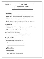
6.5 Metal Template—A square or circular template to serve
as a pattern for the excavation. Template dimensions, shapes,
and material may vary according to the size of the test pit to be
excavated. The template shall be rigid enough not to deflect or
bend.
18
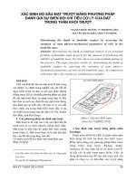
NOTE 2—The template shown in Fig. 1 represents a design that has
been found suitable for this purpose.
6.6 Liner, approximately 1⁄2-mil thick and large enough to
line the test pit with about 1 ft (0.3 m) extending beyond the
outside of the template. Any type of material, plastic sheeting,
etc., can be used as long as it is flexible enough to conform to
the ground surface.
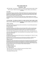
6.7 Sand Pouring Devices—(See Fig. 2 for typical devices.)
Many types of pouring devices are available. The device must
have a spout that will reach into a field test pit so that the drop
distance from the end of the spout to the sand surface can be
maintained at about 2 in. (50 mm). The inside diameter of the
spout must also be large enough to allow free flow of the sand
without clogging.
7. Hazards
7.1 Precaution:
7.1.1 These test methods may involve handling heavy loads.
7.1.2 Some sands used in the procedures outlined herein
may be dusty and appropriate precautions should be taken
when mixing and pouring.
7.2 Caution:
7.2.1 Materials that may flow or deform during the test must
be identified and appropriate precautions taken.
7.2.2 Movement of heavy equipment in the immediate test
area should not be permitted during the volume determination.
7.2.3 Errors may arise in the computed unit weight of
material due to the influence of excessive moisture in the soil.
These errors may be significant in materials with high permeability, such as sands and gravels, where the bottom of the test
hole is close to or below the water table. Errors may also arise
due to change in density of the calibrated sand as it becomes
wetted from capillary or freestanding water while performing
the test. This problem becomes evident when removing the
calibrated sand from the test hole and wet sand is observed on
the bottom or sides of the test hole. When a liner is used, the
buoyant forces of free water beneath or behind the liner may
adversely affect the volume determination.
7.2.4 Suitably protect the test area and equipment during
periods of inclement weather such as rain, snowfall, or high
wind. If the in-place moisture content value is required, it may
be necessary to protect the area from direct sunlight.
7.2.5 Numerous containers may be required during performance of these test methods. Properly label all containers to
avoid a possible mixup.
7.2.6 The total mass of the calibrated sand, or the soil
sample, or both, may exceed the capacity of the scale used,
requiring cumulative determinations of mass. Take care to
ensure that the total mass is properly determined.
7.2.7 Pouring devices with valves provide consistent sand
flow from test to test only if the valve is opened completely
FIG. 1 Typical Metal Template for Excavating Test Pit
3
D 4914
FIG. 2 Typical Sand Pouring Devices
each time. A valve that is only partially open can significantly
alter the flow characteristics of the device. Each individual
pouring device has unique characteristics which may cause the
sand to flow from it differently. The final calibration values are
affected by changes in these flow characteristics. Consequently,
calibration values are not interchangeable, even for devices
which may appear to be identical.
7.2.8 Do not allow pouring devices to run out of sand during
the pouring operation. The size of the stream of poured sand
from the pouring device should be constant. If the reservoir
capacity of the pouring device is too small to fill the test pit
with one pour, use two or more pours to fill the test pit. Stop the
stream of sand when the reservoir is about three-fourths empty
and before the size of the stream diminishes. Refill the
reservoir and resume pouring.
7.2.9 Pouring devices permit a varied sand drop distance
that must be carefully controlled if consistent results are to be
achieved. A distance of 2 in. (50 mm) from the end of the spout
4
D 4914
tions where removal of large particles would undermine the
template.
9.6 Prepare the surface of the area to be tested.
9.6.1 Remove all loose material from an area large enough
on which to place the template. Prepare the exposed surface so
that it is a firm, level plane.
9.6.2 Personnel should not step on the area selected for
testing. Provide a working platform when testing materials
which may flow or deform.
9.7 Place and seat the template on the prepared surface.
9.7.1 Use a hammer to firmly seat the template to avoid
movement of the template while the test is performed. The use
of nails, weights, or other means may be necessary to maintain
the position.
9.7.2 Remove any material loosened while placing and
seating the template, taking care to avoid leaving any void
space under the template. If necessary, fill voids under the
template with plastic soil, modeling clay, or other suitable
material, provided that this material is not subsequently excavated as part of the material removed from the test pit.
9.8 Determine the mass of sand used to fill the space
between the soil surface and the top of the template.
9.8.1 Irregularities of the soil surface within the template
must be taken into account. To do this, determine the mass of
sand required to fill the space between the soil surface and the
top of the template.
9.8.2 It is recommended that a cloth with a hole slightly
larger than the template center hole be placed over the template
to facilitate locating and collecting any excess sand, or loose
material, or both.
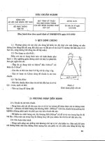
9.8.3 Place a liner (approximately 1⁄2-mil thick) over the
template and shape it by hand to conform to the irregular soil
surface and the template. The liner should extend approximately 1 ft (0.3 m) outside the template. The liner should not
be stretched too taut or contain excessive folds or wrinkles (see
Fig. 3).
9.8.4 Pour the calibrated sand onto the liner inside the
template using a sand pouring device (see Fig. 4). Slightly
overfill the template (see 7.2.7-7.2.9). Return any sand remaining in the pouring device to the original container.
9.8.5 Carefully level the calibrated sand by screeding with
the steel straightedge across the top edges of the template.
Return all screeded excess sand to the original container. Take
care to avoid the loss of any excess sand.
9.8.6 Remove the calibrated sand in the template and, if the
to the surface being poured is recommended. Variations in the
drop distance can significantly affect results. The drop distance
is directly affected by the operator’s ability to control the
pouring device and by the operator’s judgment of the drop
distance while doing so. This involves stooping while holding
a pouring device with an initial mass of 50 lbm (20 kg) or more
that is constantly changing in mass as the sand flows into the
test pit. Calibration values are notinterchangeable from device
to device and are not necessarily interchangeable from operator
to operator. Individual operators must demonstrate that they
can duplicate the calibration values for a device before they
may use them, preferably within 1 % of the average value for
another operator. Otherwise, separate calibrations for the
various operators are required.
8. Calibration and Standardization
8.1 Calibrate the sand pouring equipment and sand in
accordance with Annex A1.
9. Test Method A, Procedure—In-Place Density and Unit
Weight of Total Material
9.1 Use Test Method A to determine a total unit weight (see
1.4).
9.2 Determine the recommended sample volume and select
the appropriate template for the anticipated material gradation
in accordance with Annex A2. Assemble the remainder of the
required equipment.
9.3 Determine the mass of each combination of empty
container, lid, and container liner (if used) that will contain the
excavated material. Number the containers and mark as to use.
Write the mass on the container or prepare a separate list.
9.4 Prepare the quantity of calibrated sand to be used.
9.4.1 Two sets of calibrated sand are necessary. Determining the volume of the test pit requires two separate sand pours
to ( 1) measure the mass of sand used to fill the space between
the soil surface and the top of the template, and (2) measure the
mass of sand used to fill the test pit up to the top of the
template. The difference between the two gives the mass of
sand in the test pit.
9.4.2 Estimate the mass of calibrated sand and the number
of containers required to fill the space between the soil surface
and the top of the template. Calculate the estimated mass by
multiplying the template volume by the density of the calibrated sand. Number the containers to be used and mark as to
use, for example, “template correction.” Fill the containers
with sand. Determine and record on a separate list the mass of
the containers and sand.
9.4.3 From the anticipated volume of the test pit, estimate
the mass of calibrated sand required to fill the test pit. Increase
this amount by about 25 % to ensure that a sufficient sand
supply is available at the site, and then add to it the mass of
sand calculated in 9.4.2. Calculate the estimated mass to be
used for the test pit by multiplying the anticipated volume of
the test pit by the density of the calibrated sand. Determine the
number of containers required, number them, and mark as to
use, for example, “test pit.’’ Fill the containers with sand.
Determine and record on a separate list the mass of the
containers and sand.
9.5 Select a representative area for the test, avoiding loca-
FIG. 3 Plastic Liner Placed Over the Template
5
D 4914
weight, which would include the larger particle(s), need not be
calculated. The “control fraction’’ values determined then
become the values for the total material from the test pit. If
enough of these particles are found so that their mass is
determined to be about 5 % or more of the mass of the
excavated material, repeat the test with a larger test pit in
accordance with the guidelines in Annex A2.
9.9.6 The sides of the pit should slope inward slightly.
Materials that do not exhibit much cohesion may require a
more conical-shaped test hole.
9.9.7 The profile of the finished pit must be such that poured
sand will completely fill the excavation. The sides of the test pit
should be as smooth as possible and free of pockets or
overhangs or anything that might interfere with the free flow of
the sand.
9.9.8 Clean the bottom of the test pit of all loosened
material.
9.10 Determine the volume of the test pit.
FIG. 4 Sand Being Poured Into the Template
sand is to be reclaimed, place it in a specially marked container.
Remove the liner.
9.9 Excavate the test pit.
9.9.1 Using handtools (chisel, knife, bar, etc.), excavate the
center portion of the test pit.
9.9.1.1 Do not permit any movement of heavy equipment in
the area of the test pit as deformation of the soil within the test
pit may occur.
9.9.2 Place all material removed from the test pit in the
container(s) (see Fig. 5), being careful to avoid losing any
material (see 9.8.2).
9.9.3 Avoid moisture loss by keeping the container covered
while material is not being placed in it. Use a sealable plastic
bag inside the container to hold the material.
9.9.4 Carefully trim the sides of the excavation so that the
dimensions of the test pit at the soil-template contact are as
close as possible to that of the template hole. Avoid disturbing
the template or the material beneath or outside the template.
9.9.5 Continue the excavation to the required depth, carefully removing any material that has been compacted or
loosened in the process.
9.9.5.1 If during excavation of material from within the test
pit, a particle(s) is found that is about 11⁄2 times, or more, larger
than the maximum particle size used to establish the dimensions and minimum volume of the test pit (see Annex A2), set
the particle(s) aside and mark appropriately. Determine the
mass and volume of the particle(s) and then subtract them from
the mass and volume of the material removed from the test pit.
Consider the larger particle(s) as “oversize’’ and follow the
procedure outlined in Section 10, except that the “total’’ unit
NOTE 3—A liner may be required to prevent migration of the calibrated
sand into the natural voids of the material mass. The liner, approximately
1⁄2-mil thick, should be large enough to extend approximately 1 ft (0.3 m)
outside of the template after having been carefully placed and shaped to
the soil surface within the pit. Allowances must be made for slack. The
liner should not be stretched too taut nor contain excessive folds or
wrinkles. Inspect the linear for punctures before use.
9.10.1 Pour the calibrated sand using the sand pouring
device. Use the same pouring technique as used in the
calibration procedure described in Annex A1. Slightly overfill
the template. Return any sand remaining in the pouring device
to the original container.
9.10.1.1 While the sand is being poured, avoid any vibrations in the test area.
9.10.2 Carefully level the calibrated sand by screeding with
the steel straightedge across the top edges of the template.
Return all screeded excess sand to the original container. Take
care to avoid the loss of any excess sand.
9.10.3 If the calibrated sand is to be reclaimed, remove the
used sand and place it into a specially marked container.
Remove the liner and template.
9.11 Determine the dry unit weight.
9.11.1 Determine the mass of calibrated sand in the template
(sand used to fill the space between the soil surface and the top
of the template) as follows:
9.11.1.1 Calculate and record the total mass of the sand and
containers prepared in 9.4.2. Record the container numbers.
9.11.1.2 Determine and record the total mass of the empty
containers plus the sand residue (sand not used) and containers.
9.11.1.3 Calculate the mass of sand in the template and
record.
9.11.2 Determine the mass of calibrated sand in the test pit
and template (sand used to fill the test pit to the top of the
template) as follows:
9.11.2.1 Calculate and record the total mass of the sand and
containers prepared in 9.4.3. Record the container numbers.
9.11.2.2 Determine the total mass of the empty containers
plus the sand residue and containers and record.
9.11.2.3 Calculate the mass of sand in the test pit and
template (mass of sand used) and record.
9.11.3 Calculate the mass of the calibrated sand used to fill
FIG. 5 Excavation of the Test Pit
6
D 4914
10.5 Wash the oversize particles and reduce the free water
on the surface of the particles by blotting, draining, or a similar
method.
10.6 Determine the wet mass of the oversize particles plus a
container of predetermined mass, and record.
10.7 Calculate the wet mass of the oversize particles and
record.
10.8 Calculate the wet mass of the control fraction and
record.
10.9 Determine the volume of the oversize particles by one
of the following procedures:
10.9.1 Determine and record the mass of all oversize
particles suspended in water using the procedures and principles of Test Method C 127, disregarding the ovendrying and
24-h soaking period. Calculate and record the volume of the
oversize particles.
10.9.2 Calculate the volume of the oversize particles using
a known bulk specific gravity value. If previous tests for bulk
specific gravity of similar oversize particles from a particular
source have been performed and the value is relatively constant, a bulk specific gravity may be assumed. The bulk specific
gravity value used must correspond to the moisture condition
of the oversize particles when their mass is determined. As
used in this test method, determine the bulk specific gravity on
the oversize particles in the moisture condition as stated in
10.5-10.7. If an oven dry or saturated surface dry (SSD) bulk
specific gravity is used, then also determine the mass of the
oversize particles for this test method on oven dry or SSD
material, respectively.
10.10 Calculate the volume of the control fraction and
record.
10.11 Calculate the wet density of the control fraction.
10.12 Determine the moisture content of the control fraction
in accordance with Test Method D 2216 or C 566 (see Note 4)
and record.
10.13 Calculate the dry density and dry unit weight of the
control fraction and record.
10.14 If desired, determine and record the moisture content
of all oversize particles in accordance with Test Method
D 2216 or C 566 (see Note 4). If previous tests for moisture
content of the oversize particles from a particular source have
been performed and the value is relatively constant, a moisture
content may be assumed.
10.15 If desired, determine the percentage of oversize
particles as follows:
10.15.1 Calculate the dry mass of the control fraction and
record.
10.15.2 Calculate the dry mass of the oversize particles and
record.
10.15.3 Calculate the dry mass of the total sample and
record.
10.15.4 Calculate the percentage of oversize particles and
record.
10.16 Calculate the moisture content of the total material.
10.17 If desired, calculate the dry density and dry unit
weight of the total material and record.
the test pit and record.
9.11.4 Record the density of the calibrated sand (determined
in the calibration procedure described in Annex A1).
9.11.5 Calculate the volume of the test pit and record.
9.11.6 Determine the total mass of the excavated material
and containers.
9.11.7 Calculate and record the total mass of the containers
used to hold the excavated material. Record the container
numbers.
9.11.8 Calculate the mass of the excavated material and
record.
9.11.9 Calculate the wet density of the excavated material.
9.11.10 If the excavated material contains oversize particles
(normally larger than the No. 4 (4.75-mm) sieve for cohesive
materials and 3-in. (75-mm) sieve for cohesionless materials),
separate the material using the appropriate size sieve. If the
material contains about 3 % (wet basis) or more oversize
particles, Test Method B should be used.
9.11.11 If 2 % or less oversize particles are present, obtain a
moisture content specimen representative of the excavated
material and determine the moisture content in accordance with
Test Method D 2216 or C 566 and record.
NOTE 4—For rapid moisture content determination of materials containing less than 15 % fines (minus No. 200), use a suitable source of heat
such as an electric or gas hotplate. If a source of heat other than the
controlled temperature oven is used, stir the test specimen to accelerate
drying and avoid localized overheating. The material may be considered
dry when further heating causes, or would cause, less than 0.1 %
additional loss of mass.
9.11.12 If required or desired, calculate and record the dry
density and dry unit weight of the material.
10. Test Method B, Procedure—In-Place Density and
Unit Weight of Control Fraction
10.1 This test method is used when the material being tested
contains oversize particles and the percent compaction or
percent relative density of the control fraction are to be
determined (see 1.4).
10.2 Obtain the in-place wet density of total material by
following the procedure for Test Method A, as stated in
9.1-9.11.9.
10.3 To obtain the wet density of the control fraction,
determine the mass and volume of the oversize particles and
subtract them from the total mass and total volume to get the
mass and volume of the control fraction. Then calculate the
density of the control fraction from the mass and volume of the
control fraction.
10.3.1 Normally, the wet density of the control fraction is
determined and the dry density calculated using the moisture
content of the control fraction.
10.3.2 In addition, the moisture content of the oversize
particles, the moisture content of the total material, and the
percentage of oversize particles may be determined.
10.4 After obtaining the wet mass of total material removed
from the test pit, separate the material into the control fraction
and the oversize particles using the designated sieve. Do this
rapidly to minimize loss of moisture. If the test is for
construction control, place the control fraction in an airtight
container for further tests.
7
D 4914
11. Test Method A, Calculation
where:
of material excavated from test pit,
rwet 5 wet density
3
lbm/ft (Mg/m3),
m10 5 mass of wet material removed from test pit, lbm
(kg), and
VT 5 volume of test pit, ft3 (m3).
11.7 Calculate the dry density of the material removed from
test pit as follows:
11.1 Calculate the mass of the sand contained in the
template as follows:
m6 5 m 2 2 m4
(1)
where:
m 6 5 mass of sand in template, lbm (kg),
m2 5 mass of template sand and container(s) (before test),
lbm (kg), and
m4 5 mass of template sand residue and container(s) (after
test), lbm (kg).
11.2 Calculate the mass of the sand used to fill the test pit
and template as follows:
m 5 5 m1 2 m3
rd 5
(2)
1 lbf
gd 5 rd 3 1 lbm
(3)
(4)
gd 5 r d 3 9.807
(5)
where:
9.807 5 the constant to convert Mg to kN.
11.9 If required, convert dry unit weight in inch-pound units
to SI units as follows:
where:
VT 5 volume of test pit, ft3(m3),
m7 5 mass of sand in test pit, lbm (kg), and
rs 5 density of calibrated sand, lbm/ft3 (Mg/m3).
11.5 Calculate the mass of the wet material removed from
test pit as follows:
m10 5 m 8 2 m9
unit weight, kN/m 3 5 unit weight, lbf/ft 3 3 0.1571
(6)
(12)
12. Test Method B, Calculation
12.1 Calculate the wet mass of the oversize particles as
follows:
m13 5 m 11 2 m12
(13)
where:
m 13 5 wet mass of oversize particles, lbm (kg),
m11 5 wet mass of oversize particles and container, lbm
(kg), and
m12 5 mass of container, lbm (kg).
12.2 Calculate the wet mass of the control fraction as
follows:
(7)
(SI)
m18 5 m 10 2 m13
m10
1
rwet 5 V 3 3
10
T
(11)
where:
0.1571 5 the constant to convert pounds-force per cubic
feet to kilonewton per cubic metre.
where:
m 10 5 mass of wet material removed from test pit, lbm
(kg),
5 mass of wet material removed from test pit plus
m8
mass of container(s), lbm (kg), and
5 mass of container(s) for m8, lbm (kg).
m9
11.6 Calculate the wet density of the material removed from
test pit as follows:
(inch-pound)
m10
rwet 5 V
T
(10)
Assume that in the inch-pound system 1 lbm 5 1 lbf.
(SI)
(SI)
m7
1
VT 5 r 3 3
10
s
(9)
where:
gd 5 dry unit
weight of material excavated from test pit,
3
lbf/ft (kN/m3), and
rd 5 dry density of material from test pit, lbm/ft3 (Mg/m3).
where:
m 7 5 mass of sand in test pit, lbm (kg),
m5 5 mass of sand used, lbm (kg), and
m6 5 mass of sand in template, lbm (kg).
11.4 Calculate the volume of the test pit as follows:
(inch-pound)
m7
VT 5 r
s
S D
where:
rd
5 dry density of material from test pit, lbm/ft3 (Mg/
m3),
rwet 5 wet density
of material excavated from test pit,
3
lbm/ft (Mg/m 3), and
w
5 moisture content of material excavated from test pit,
%.
11.8 Calculate the dry unit weight of the material removed
from test pit as follows:
(inch-pound)
where:
m 5 5 mass of sand used, lbm (kg),
m1 5 mass of sand and container(s) (before test), lbm (kg),
and
m 3 5 mass of sand residue and container(s) (after test),
lbm (kg).
11.3 Calculate the mass of the sand used to fill the test pit as
follows:
m7 5 m 5 2 m6
rwet
w
1 1 100
(8)
where:
8
(14)
D 4914
m 18 5 wet mass of control fraction, lbm (kg),
m10 5 mass of wet material removed from test pit, lbm
(kg), and
m13 5 wet mass of oversize particles, lbm (kg).
12.3 Calculate the volume of the oversize particles based on
the mass in air and mass in water method as follows:
(inch-pound)
m13 2 m14
62.4 lbm/ft3
(15)
m13 2 m14
1
3 3
1 g/cm3
10
(16)
Vos 5
rd ~c! 5
where:
62.4 lbm/ft3
1 g/cm3
1
3
10
m
1 lbf
gd ~c! 5 rd ~c! 3 1 lbm
gd ~c! 5 r d ~c! 3 9.807
5 wet mass of oversize particles, lbm (kg),
and
5 mass of oversize particles suspended in
m14
water, lbm (kg).
12.4 Calculate the volume of the oversize particles based on
a known bulk specific gravity as follows:
(inch-pound)
m13
Gm 3 ~62.4!
(17)
m 13
1
3
Gm 3 ~1 g/cm3! 103
(18)
12.9 If required, convert dry unit weight in inch-pound
units, to SI units, using Eq 12.
12.10 Calculate the dry mass of the control fraction as
follows:
m19 5
where:
Vos 5 volume of oversize particles, ft3 (m3),
m13 5 wet mass of oversize particles, lbm (kg), and
Gm 5 bulk specific gravity of oversize particles.
12.5 Calculate the volume of the control fraction as follows:
m18
1
rwet ~c! 5 V 3 3
10
c
(21)
S D
m17 5 m15 2 m 16
where:
Vc 5 volume of control fraction, ft3 (m3),
VT 5 volume of test pit, ft3 (m 3), and
Vos 5 volume of oversize particles, ft3 (m3).
12.6 Calculate the wet density of the control fraction as
follows:
(inch-pound)
(20)
m18
wf
1 1 100
(25)
where:
m 19 5 dry mass of control fraction, lbm (kg),
m18 5 wet mass of control fraction, lbm (kg), and
5 moisture content of control fraction, %.
wf
12.11 Calculate the dry mass of the oversize particles using
one of the following equations as appropriate:
(19)
m18
rwet ~c! 5 V
c
(24)
where:
9.807 5 constant to convert Mg to kN,
gd (c) 5 dry unit weight of control fraction, lbf/ft3 (kN/
m3), and
r d (c) 5 dry density of control fraction, lbm/ft 3 (Mg/m3).
(SI)
Vc 5 V T 2 Vos
(23)
Assume that in the inch-pound system 1 lbm 5 1 lbf.
(SI)
13
Vos 5
(22)
5 dry density of control fraction, lbm/ft 3 (Mg/m3),
5 wet density of control fraction, lbm/ft3 (Mg/m
3), and
wf
5 moisture content of control fraction, %.
12.8 Calculate the dry unit weight of the control fraction as
follows:
(inch-pound)
5 density of water,
5 density of water,
5 constant to convert g/cm3 to kg/m3,
Vos 5
S D
where:
r d (c)
rwet(c)
(SI)
Vos 5
rwet~c!
wf
1 1 100
m17 5
m13
wos
1 1 100
S D
(26)
(27)
where:
m 17 5 dry mass of oversize particles, lbm (kg),
m15 5 dry mass of oversize particles and container, lbm
(kg),
m16 5 mass of container, lbm (kg),
m13 5 wet mass of oversize particles, lbm (kg), and
wos 5 moisture content of oversize particles, %.
12.12 Calculate the dry mass of the total sample as follows:
(SI)
m20 5 m19 1 m 17
where:
rwet (c)
5 wet density of control fraction, lbm/ft3 (Mg/m
3),
m18
5 wet mass of control fraction, lbm (kg), and
5 volume of control fraction, ft3 (m3).
Vc
12.7 Calculate the dry density of the control fraction as
follows:
(28)
where:
m 20 5 dry mass of total sample (control fraction plus
oversize), lbm (kg),
m19 5 dry mass of control fraction, lbm (kg), and
m17 5 dry mass of oversize particles, lbm (kg).
12.13 Calculate the percent oversize particles as follows:
9
D 4914
m17
p 5 m 3 100
13.1.6 In-place dry unit weight, total or control fraction, or
both.
13.1.7 In-place moisture content(s), total or control fraction,
and test method used.
13.1.8 Test apparatus description.
13.1.9 Description of calibration procedures.
13.1.10 Density of calibrated sand.
13.1.11 Comments on test, as applicable.
13.1.12 Visual description of material.
13.1.13 If determined or assumed, bulk specific gravity and
test method used.
13.1.14 If required, percentage of oversize particles.
(29)
20
where:
p
5 percent oversize,
m17 5 dry mass of oversize particles, lbm (kg), and
m20 5 dry mass of total sample (control fraction plus
oversize), lbm (kg).
12.14 Calculate the moisture content of the total material as
follows:
w5
m10 2 m20
3 100
m 20
(30)
where:
w
5 moisture content of material excavated from test
pit, %,
m10 5 mass of wet material removed from test pit, lbm
(kg), and
m 20 5 dry mass of total sample (control fraction plus
oversize particles), lbm (kg).
12.15 Calculate the dry density and dry unit weight of the
total material by using Eq 9 or Eq 10 and 11).
12.16 If required, convert dry unit weight in inch-pound
units, to SI units, using Eq 12.
14. Precision and Bias
14.1 Precision—Test data on precision is not presented due
to the nature of the soil and rock materials being tested by these
test methods. It is not feasible at this time to have ten or more
agencies participate in an in situ testing program at a given site.
Also, it is not feasible to produce multiple test locations having
uniform properties. Any variation observed in the data is just as
likely to be due to specimen variation as operator or laboratory
testing variation.
14.1.1 Subcommittee D 18.08 is seeking any data from
users of these test methods that might be used to make a limited
statement on precision.
14.2 Bias—There is not accepted reference value for these
test methods, therefore, bias cannot be determined.
13. Report
13.1 Report the following information, as appropriate:
13.1.1 Test location.
13.1.2 Test location elevation.
13.1.3 Test hole volume.
13.1.4 In-place wet density, total or control fraction, or both.
13.1.5 In-place dry density, total or control fraction, or both.
15. Keywords
15.1 acceptance test; degree of compaction; density tests;
field test; In-place density; pit test; quality control; sand
replacement method
ANNEXES
(Mandatory Information)
A1. CALIBRATING SAND POURING EQUIPMENT AND SAND
A1.1 Scope
A1.1.1 This annex describes the procedure for calibrating
sand pouring equipment and sand.
A1.1.2 The calibration determines an average density of
poured sand for use in calculating the volume of a test pit
excavated to determine in-place unit weight of soil and rock.
A1.3.2.1 When a new supply of sand is processed into the
storage bin.
A1.3.2.2 At intervals not exceeding 14 days when several
unit weight tests are required on a daily basis.
A1.3.2.3 If tests are made at infrequent intervals, the sand
must be calibrated before a test or series of tests is begun.
A1.3.2.4 For any change in equipment, personnel, or size or
shape of the field test pit, (see 7.2.7-7.2.9).
A1.3.2.5 After any significant changes in atmospheric humidity, or change in moisture of the sand. The sand should be
as dry as possible.
A1.2 Summary of Test Method
A1.2.1 Using a specific pouring device, sand is poured into
a calibration mold of similar size and shape of a field test pit to
determine the density of the sand as poured under specific
conditions.
NOTE A1.1—Most sands have a tendency to absorb moisture from the
atmosphere. A very small amount of absorbed moisture can make a
substantial change in bulk density. In areas of high humidity or where the
humidity changes often, the bulk density may need to be determined more
often than the 14-day maximum interval indicated. The need for more
frequent checks can be determined by comparing the results of different
bulk-density tests on the same sand made in the area and conditions of use
over a period of time.
A1.3 Significance and Use
A1.3.1 This calibration procedure is performed to obtain the
value of density of the sand using a specific pouring device for
use in measuring the volume of a field unit weight test pit.
A1.3.2 This procedure should be performed:
10
D 4914
A1.3.2.6 If tests are routinely made using reclaimed sand,
calibrate when the cumulative mass of sand removed from the
storage container equals the capacity of the container. A record
of the mass of sand removed should be kept at a convenient
location on or near the container.
A1.7.2 Place the calibration mold on a rigid surface.
A1.7.3 Using the pouring device, pour the sand into the
calibration mold, slightly overfilling. Use a circular motion to
keep the sand surface relatively level. Keep the end of the
spout about 2 in. (50 mm) above the sand surface while
pouring. A constant sand drop distance and the avoidance of
any vibration of the measure are critical to the achievement of
consistent results (see A1.5.2).
A1.7.3.1 If the reservoir capacity is too small to fill the
calibration mold with one pour, use two or more pours to fill
the mold. See 7.2.8 for the procedure to follow when more than
one pour is necessary.
A1.7.4 Strike off the excess sand even with the top of the
calibration mold using the metal straightedge (see A1.5.2.2).
A1.7.5 Determine the mass of the sand and calibration mold
and record.
A1.7.6 Calculate the mass of sand in the calibration mold
and record.
A1.7.7 Calculate the density of the sand and record.
A1.7.8 Repeat the procedure in A1.7.1-A1.7.7 as a second
trial.
A1.7.9 Determine the uniformity of the two values obtained
by dividing either value by the other. If the value of the ratio is
between 0.990 and 1.010, inclusive, average the two values and
record the average density. If the value of the ratio falls outside
the limits, go to A1.7.10.
A1.7.9.1 Compare the average density with previously determined values to see if it is consistent and reasonable. If it is
not, go to A1.7.10.
A1.7.10 Check to see that all equipment is performing
correctly, that all calibrations are correct, and that the procedures and techniques used are correct. If no problems are
discovered, then repeat procedure. If the values are still
inconsistent, go to A1.7.11.
A1.7.11 Thoroughly mix all the sand being represented by
this calibration and repeat the procedure. If the values are still
inconsistent, discard all the sand and repeat the procedure
using fresh sand from the original supply.
A1.4 Apparatus
A1.4.1 Metal Straightedge—About 2 in. (50 mm) high, at
least 1⁄8in. (3 mm) thick, and with a length 1.5 times the side
length of the calibration mold.
A1.4.2 Mold—A mold or container is required that is
similar to the size and shape of the test pit excavated in the
material. The volume of the mold shall be determined in
accordance with the principles described in Test Method
D 4253.
A1.4.3 Miscellaneous Equipment—Buckets to mix and reclaim sand, pans, thick paper, and miscellaneous brushes and
scoops for reclaiming sand.
A1.5 Technical Hazards
A1.5.1 Consistent sand flow (see 7.2.7-7.2.9).
A1.5.2 Vibration of Poured Sand:
A1.5.2.1 Any vibration or jarring of poured sand, whether
the pouring process is complete or not, causes densification of
the sand and results in erroneous test results. To achieve
consistent results, the sand must be free to flow without any
outside agitation.
A1.5.2.2 Striking off material above the top of the calibration mold must be done consistently with as little vibration as
possible.
A1.5.2.3 Place calibration molds on rigid, vibration free
surfaces while performing the calibration.
A1.5.3 Reclaimed Sand:
A1.5.3.1 As a general rule, reclaiming sand is no longer
desirable or economically feasible.
A1.5.3.2 If sand is reclaimed, after each recovery it must be
screened over a sieve that would pass its original maximum
particle size to eliminate clay balls or other foreign matter.
Discard the sand after three usages.
A1.6 Conditioning
A1.6.1 Store the sand in covered bins or containers to
maintain a uniformly dry condition. A 55-gal barrel with a
valve near the bottom makes an excellent storage container. An
internal heat source, such as a heat tape, may be necessary in
storage containers in areas that experience significant changes
in atmospheric moisture.
A1.6.2 When a new supply of sand is introduced into the
storage bin and before each calibration, thoroughly mix the
sand and blend. Calibration records must document new
shipments of sand and dates that new sand is introduced into
the current storage bin.
A1.8 Calculation
A1.8.1 Calculate the density of the sand as follows:
(inch-pound)
m
rs 5 V
(A1.1)
m
1
rs 5 V 3 3
10
(A1.2)
(SI)
where:
rs 5 density of sand, lbm/ft3 (Mg/m3),
m 5 mass of sand in calibration mold, lbm (kg), and
V 5 volume of calibration mold, ft3 (m3).
A1.7 Procedure
A1.7.1 Determine and record the mass of the mold.
11
D 4914
A2. GUIDELINES FOR TEST HOLE OR TEST DIMENSIONS AND SELECTION OF EQUIPMENT
A2.1 This annex covers guidelines for selecting the excavation dimensions and the type of equipment to use based on
the maximum particle size present in the material (or control
fraction) being tested. These guidelines apply to both these test
methods and to the companion Test Method D 5030 for using
water replacement to determine the volume of an excavated
test pit. The guidelines are given in Table A2.1 and Table A2.2.
(Metric equivalents for these two tables are provided in Table
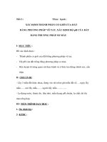
A2.3.) The typical types of test pit excavation shapes are
shown in Fig. A2.1.
A2.3 The guidelines shown in Table A2.1 apply to test pit
Types A and B (see Fig. A2.1). These test pits generally are for
non-free draining materials or for cohesionless materials whose
gradation and particle angularity will allow near-vertical side
walls to be excavated.
A2.4 The guidelines shown in Table A2.2 apply to test pit
Type C (see Fig. A2.1). This type of test pit can be excavated
when Type A or B cannot. For this case, the slope of the side
walls will be much flatter, approximately the angle of repose of
the material.
A2.2 These guidelines are based on providing a representative sample of the material being tested and on practical
working conditions. For a discussion of the shape and dimensions of the test pits and for the minimum volumes for the
excavation, see Appendix X1 in Test Method D 5030 .
A2.5 These guidelines are only applicable when the limitations stated in 1.5 and 1.6 for unstable or soft materials are
followed.
TABLE A2.1 Test Apparatus and Minimum Excavation VolumeA
NOTE 1—More than 18-in. maximum particle size should be determined on a case-by-case basis.
Maximum
Particle
Size in.B
Minimum
Required
Volume,
ft3
Suggested Apparatus and
Template Opening
Required
Minimum
Depth,
in.C
3
5
8
12
18
1.0
2
8
27
90
24-in. square frame
30-in. square frame
4-ft diameter ring
6-ft diameter ring
9-ft diameter ring
18
12
24
24
36
A
Test Pit Types A and B (see Fig. A2.1).
Maximum particle size present in total material or the maximum particle size of
control fraction if the total in-place unit weight is not of concern.
C
This depth is necessary to obtain the minimum required volume of material
when using the suggested apparatus and template opening.
B
12
D 4914
TABLE A2.2 Test Apparatus and Minimum Excavation VolumeA
NOTE 1—More than 8-in. maximum particle size should be determined
on a case-by-case basis.
Maximum
Particle
Size, in.B
3
5
8
Minimum Suggested Apparatus
Required
and Template
Volume, ft3
Opening
1.0
2
8
33-in. square frame
40-in. square frame
62-in. diameter ring
Required
Minimum
Depth, in.C
Approximate
Diameter of
Excavated
Hole, in.
10
12
18
30
35
54
A
Test Pit TypeC (see Fig. A2.1).
Maximum particle size present in total material or the maximum particle size of
control fraction if the total in-place unit weight is not of concern.
C
This depth is necessary to obtain the minimum required volume of material
when using the suggested apparatus and template opening.
B
TABLE A2.3 Metric Equivalents for Table A2.1 and Table A2.2
Inches
Millimetres
3
5
8
10
12
18
24
30
33
35
36
40
54
62
75
125
200
250
300
450
600
750
825
875
900
1000
1350
1550
Feet
Metres
4
6
9
1.2
1.8
2.7
Cubic Feet
Cubic Metres
1.0
2
8
27
90
0.03
0.06
0.23
0.76
2.55
13
D 4914
FIG. A2.1 Test Pit Configurations
SUMMARY OF CHANGES
In accordance with Committee D-18 policy, this section identifies the location of changes to this standard since
the last edition 89 (1994)e1 that may impact the use of this standard.
(1) Added Practice D 3740 to Section 2.
(2) Added new note in 5.2 on the use of Practice D 3470.
(3) Renumbered existing notes.
(4) Revised Precision and Bias Statement to conform to
Committee D-18 Policy.
(5) Added Summary of Changes.
The American Society for Testing and Materials takes no position respecting the validity of any patent rights asserted in connection
with any item mentioned in this standard. Users of this standard are expressly advised that determination of the validity of any such
patent rights, and the risk of infringement of such rights, are entirely their own responsibility.
This standard is subject to revision at any time by the responsible technical committee and must be reviewed every five years and
if not revised, either reapproved or withdrawn. Your comments are invited either for revision of this standard or for additional standards
and should be addressed to ASTM Headquarters. Your comments will receive careful consideration at a meeting of the responsible
technical committee, which you may attend. If you feel that your comments have not received a fair hearing you should make your
views known to the ASTM Committee on Standards, at the address shown below.
This standard is copyrighted by ASTM, 100 Barr Harbor Drive, PO Box C700, West Conshohocken, PA 19428-2959, United States.
Individual reprints (single or multiple copies) of this standard may be obtained by contacting ASTM at the above address or at
610-832-9585 (phone), 610-832-9555 (fax), or (e-mail); or through the ASTM website (www.astm.org).
14