C1693 11
Bạn đang xem bản rút gọn của tài liệu. Xem và tải ngay bản đầy đủ của tài liệu tại đây (204.11 KB, 7 trang )
Designation: C1693 – 11
Standard Specification for
Autoclaved Aerated Concrete (AAC)1
This standard is issued under the fixed designation C1693; the number immediately following the designation indicates the year of
original adoption or, in the case of revision, the year of last revision. A number in parentheses indicates the year of last reapproval. A
superscript epsilon (´) indicates an editorial change since the last revision or reapproval.
C33 Specification for Concrete Aggregates
C39/C39M Test Method for Compressive Strength of Cylindrical Concrete Specimens
C144 Specification for Aggregate for Masonry Mortar
C150 Specification for Portland Cement
C332 Specification for Lightweight Aggregates for Insulating Concrete
C595/C595M Specification for Blended Hydraulic Cements
C618 Specification for Coal Fly Ash and Raw or Calcined
Natural Pozzolan for Use in Concrete
C1692 Practice for Construction and Testing of Autoclaved
Aerated Concrete (AAC) Masonry
E4 Practices for Force Verification of Testing Machines
E575 Practice for Reporting Data from Structural Tests of
Building Constructions, Elements, Connections, and Assemblies
1. Scope
1.1 This specification covers autoclaved aerated concrete
(AAC), a cementitious product based on calcium silicate
hydrates in which low density is attained by the inclusion of an
agent resulting in macroscopic voids, and in which curing is
carried out using high-pressure steam.
1.2 The raw materials used in the production of autoclaved
aerated concrete are portland cement or blended cements,
quartz sand, water, lime, gypsum or anhydrite, and an agent
resulting in macroscopic voids. The quartz sand used as a raw
material may be replaced by a siliceous fine aggregate other
than sand, and usually is ground to a fine powder before use.
Fly ash may be used as a sand replacement. The batched raw
materials are mixed thoroughly together to form a slurry. The
slurry is cast into steel molds. Due to the chemical reactions
that take place within the slurry, the volume expands. After
setting, and before hardening, the mass is machine cut into
units of various sizes. The units then are steam-cured under
pressure in autoclaves where the material is transformed into a
hard calcium silicate.
1.3 The values stated in inch-pound units are to be regarded
as standard. The values given in parentheses are mathematical
conversions to SI units that are provided for information only
and are not considered standard.
1.4 This standard does not purport to address all of the
safety concerns, if any, associated with its use. It is the
responsibility of the user of this standard to establish appropriate safety and health practices and determine the applicability of regulatory limitations prior to use. See Section 6, 7,
and 8.
3. Classification
3.1 AAC units manufactured in accordance with this specification are classified according to their strength class.
4. Materials and Manufacture
4.1 Raw Materials—Materials shall conform to the following applicable specifications:
4.1.1 Portland Cement, Specification C150.
4.1.2 Blended Cements, Specification C595/C595M.
4.1.3 Pozzolan, Specification C618.
4.1.4 Gypsum, Specification C22/C22M.
4.1.5 Aggregates, Specifications C33, C144, or C332.
5. Physical Requirements
5.1 Compressive Strength—The compressive strength shall
be determined according to Section 6 and shall conform to the
requirements of Table 1.
5.2 Dry Bulk Density—The dry bulk density shall be determined according to Section 7 and shall conform to the
requirements of Table 1.
5.3 Drying Shrinkage—The drying shrinkage shall be determined in accordance with Section 8, and shall conform to
the requirements of Table 1.
5.4 Modulus of Elasticity—If required, the modulus of
elasticity shall be determined in accordance with Section 9.
2. Referenced Documents
2.1 ASTM Standards:2
C22/C22M Specification for Gypsum
1
This specification is under the jurisdiction of ASTM Committee C27 on Precast
Concrete Products and is the direct responsibility of Subcommittee C27.60 on
Precast Autoclaved Aerated Concrete.
Current edition approved July 15, 2011. Published August 2011. Originally
approved in 2009. Last previous edition approved in 2009 as C1693 – 09 ´1. DOI:
10.1520/C1693-11.
2
For referenced ASTM standards, visit the ASTM website, www.astm.org, or
contact ASTM Customer Service at For Annual Book of ASTM
Standards volume information, refer to the standard’s Document Summary page on
the ASTM website.
Copyright © ASTM International, 100 Barr Harbor Drive PO box C-700 West Conshohocken, Pennsylvania 19428-2959, United States
1
C1693 – 11
TABLE 1 Physical RequirementsA
Strength Class
Compressive Strength,
psi (MPa)
AAC-2
290 (2.0)
AAC-3
435 (3.0)
AAC-4
580 (4.0)
AAC-5
725 (5.0)
AAC-6
870 (6.0)
Nominal Dry
Bulk Density,
lb/ft3(kg/m3)
min
A
25
31
31
37
31
37
37
44
37
44
(400)
(500)
(500)
(600)
(500)
(600)
(600)
(700)
(600)
(700)
Density Limits,
lb/ft3(kg/m3)
Lower Limit >
22
28
28
34
28
34
34
41
35
41
(350)
(450)
(450)
(550)
(450)
(550)
(550)
(650)
(550)
(650)
Upper Limit #
28
34
34
41
34
41
41
47
41
47
(450)
(550)
(550)
(650)
(550)
(650)
(650)
(750)
(650)
(750)
The average drying shrinkage requirement of all strength classes is #0.02 %.
6. Determination of Compressive Strength
6.1 Apparatus:
6.1.1 Testing Machine—The testing machine shall conform
to the requirements prescribed in Practice E4. The machine
shall be equipped with two steel bearing blocks one of which
is a spherically seated block that will transmit load to the upper
surface of the specimen, and the other a plane rigid block on
which the specimen will rest.
6.2 Test Specimens:
6.2.1 Three cube specimens of 4 in. (100 mm) edge length
shall be tested in an air dried condition (5 to 15 % by mass
moisture content). If the samples have to be dried before
testing to reach that moisture content, they shall be stored at a
temperature not exceeding 158°F (70°C).
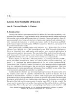
6.2.2 A minimum of three specimens shall be tested. Whenever possible, one specimen shall be obtained from the upper
third of the product, one from the middle, and one from the
lower third, determined in the direction of the rising of the
mass during manufacture. Otherwise, the position of the cubes
and information regarding the rise shall be reported. The
direction of the rise shall be noted on all specimens. This is
shown in Fig. 1.
6.2.3 Loadbearing surfaces of the specimen shall be plane
within 0.0035 in. (0.09 mm) per 4 in. (100 mm). This can be
achieved by grinding, milling, or capping. When capping, a
gypsum plaster compound shall be used.
6.3 Procedure:
6.3.1 The specimen shall be placed in the testing machine
and the load applied perpendicular to the direction of rise
during manufacture.
6.3.2 Speed of Testing—Apply the load up to one half of the
expected maximum load at a convenient rate, after which
adjust the controls of the machine as required to give a uniform
rate of travel of the moving head such that the remaining load
is applied in not less than one nor more than two minutes.
6.3.3 Calculate the compressive strength of each specimen
as follows:
P
Compressive strength, f 5 A
where:
f = compressive strength of the specimen, psi (or Pa),
P = maximum load, lbf (or N), indicated by the testing
machine, and
A = gross cross-sectional area of the specimen, in.2 (mm2).
6.4 The compressive strength shall be reported to the
nearest 10 psi (69 kPa) for each specimen and as the average
for three specimens.
7. Determination of Moisture Content and Bulk Density
7.1 Apparatus:
7.1.1 Balance—shall be sensitive within 0.5 % of the mass
of the specimen.
7.2 Test Specimens—Three test specimens, as described in
8.2, shall be used for calculating the bulk density.
7.3 Procedure:
7.3.1 Determine the mass of the specimens, and then dry
them in a ventilated oven at 212 to 230°F (100 to 110°C) for
not less than 24 h, and until two successive determinations of
mass at intervals of 2 h show an increment of loss not greater
than 0.2 % of the last previously determined mass of the
specimen.
7.3.2 Calculate the moisture content of each specimen as
follows:
Moisture Content %, MC 5 ~A–B!/B 3 100
(2)
where:
MC = moisture content, %,
A
= sampled mass of specimen, lb (kg), and
B to = dry mass of specimen, lb (kg).
7.3.2.1 Report the average moisture content of all of the
specimens as the moisture content of the lot.
7.3.3 Determine the dimensions of the test specimens with a
caliper gauge. Measure the width and height at the ends and in
the middle of the length of the specimen. Measure the length
on two opposite sides. Determine the volume of the specimen
by multiplying the average values of the dimensions.
7.3.4 Calculate the dry bulk density of each specimen as
follows:
(1)
2
C1693 – 11
FIG. 1 Direction of Loading
g 5 B/V
(3)
8.1.2 Caliper Gage, shall be accurate to 0.004 in. (0.1 mm).
8.1.3 Temperature Regulated Environment, capable of regulating the temperature to 68 6 4°F (20 6 2°C) and a minimum
relative humidity of 45 % in which the samples are stored
during drying and while the measurements in the change in
length are performed.
8.1.4 Measuring Instrument, used to determine the change
in length of the test samples. Any suitable device shall be
permitted to be used provided it meets the following requirements:
8.1.4.1 The instrument shall measure change in length along
the longitudinal axis of the sample.
where:
g = dry bulk density, lb/ft3 (kg/m3),
B = dry mass of specimen, lb (kg), and
V = volume of the specimen, ft3 (m3).
7.3.4.1 Report the average dry bulk density of all of the
specimens as the dry bulk density of the lot.
8. Determination of Drying Shrinkage
8.1 Apparatus:
8.1.1 Balance, shall be sensitive to within 0.1 % of the mass
of the specimen.
3
C1693 – 11
does not change by more than 0.2 %. After a constant mass is
reached, the measurement marks shall be removed, and the
mass determined.
8.5 Calculation of Test Results:
8.5.1 Calculate the relative change in length between readings as follows:
8.1.4.2 The instrument shall be able to make contact with
the measurement marks fastened to the face of the samples.
8.1.4.3 The measurements shall be made with an accuracy
of DL/L[ogr]# 10-6, where L[ogr] is the original length of the
sample
8.1.4.4 The instrument shall have a measuring precision
consistent with the accuracy required in 8.1.4.3.
8.1.4.5 The instrument shall be checked with a measurement standard prior to each measurement.
8.1.5 Measurement Marks, fastened to the faces of the
samples, shall be made of a corrosion-resistant material and
shaped so that reliable contact with the measuring instrument is
assured.
8.1.6 Ventilated Drying Oven, capable of maintaining a
temperature of 220 6 8°F (105 6 5°C).
8.2 Test Specimens:
8.2.1 Use prism specimens measuring 1.5 by 1.5 by 6.3 in.
(40 by 40 by 160 mm), and use at least three specimens for
each test. Whenever possible, obtain one specimen from the
upper third of the product, one from the middle, and one from
the lower third, determined by the direction of the rising of the
mass during manufacture. Otherwise, report the position of the
sample and the direction of rise. Note the direction of rise on
all specimens.
8.2.2 The longitudinal axis of the specimen shall be normal
to the direction of rise and preferably parallel with the
longitudinal direction of the product. Cement the measurement
marks or otherwise securely fasten them to the faces of the
specimen.
8.3 Measurement and Conditioning of Test Specimens:
8.3.1 Measure the dimensions of the test specimens with a
caliper gauge. Measure the width and height at the ends and in
the middle of the length of the specimen. Measure the length
on two opposite sides. Determine the volume of the specimen
by multiplying the average values of the dimensions.
8.3.2 The samples shall be packaged in plastic and stored
for a minimum of 24 h at 68 6 4°F (20 6 2°C) to obtain a
uniform moisture distribution. The moisture content shall be
determined as follows:
MC 5 ~gm – gdb!/gdb 3 100
´si 5
~L@ogr] – Lf!
DL
L@ogr] 3 100 5 L@ogr] 3 100
(5)
where:
DL
= change in measured length according to 8.4.1 in
in. (mm),
L[ogr] = the initial length of the specimen, and
= the final length of the specimen.
Lf
8.5.1.1 The relative change in length shall be reported with
an accuracy of 0.00001 in./in. (0.00001 mm/mm).
8.5.2 The moisture content at each reading time shall be
calculated as follows:
MC 5
~ mi – m d !
3 100
~md – mmark!
(6)
where:
MC
= moisture content,
= mass of the damp sample at the reading time in lb
mi
(kg),
= mass of the sample unit after drying in lb (kg),
md
and
mmark = mass of the measurement mark in lb (kg).
8.5.2.1 The moisture content shall be reported with an
accuracy of 0.1 %.
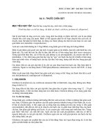
8.5.3 The average values for the relative change in length
and the moisture content for each reading shall be shown
graphically and connected by a curve (Fig. 2). The amount of
drying shrinkage, ´cs, is the difference in the relative change in
length between the moisture contents of 30 and 6 %.
9. Determination of the Modulus of Elasticity of AAC in
Compression
9.1 Test Apparatus—The test apparatus shall be as follows:
9.1.1 Testing Machine—The testing machine shall conform
to Practices E4 (Constant-Rate-of-Traverse CRT-Type Testing
Machine). The spherical head and bearing blocks shall conform to the Apparatus section of Test Method C39/C39M.
9.1.2 Calipers—Calipers shall allow a reading with a precision of 0.1 mm.
9.1.3 Drying Ovens—Two ovens typically are used for this
test procedure; one maintained at a temperature of 105 6 5°C
and another maintained at a temperature of 70 6 5°C.
9.1.4 Compressometer may be used to determine the strain
behavior of the specimen during compression and shall have a
precision of 0.001 mm.
9.2 Test Specimens—The test specimens shall be as follows:
9.2.1 Shape of Specimens—The specimens shall be prisms
measuring 100 mm (4 in.) by 100 mm (4 in.) by 200 mm (8
in.). Prisms of other sizes or cylindrical specimens shall be
permitted to be used provided that the width (diameter) of such
other specimens is not less than 75 mm (3 in.) and the ratio
between the height and the width shall be 2.
(4)
where:
gm = mm/V, wet bulk density as determined by the mass in
the damp condition divided by the volume, and
gdb = dry bulk density of a comparative sample as determined in Section 7.
8.4 Determination of Drying Shrinkage:
8.4.1 Clean the measurement marks before each reading.
Make the first determination of length and mass immediately
after removing the specimen from the plastic enclosure. Then
store the specimen on a grid to allow sufficient movement of air
around the specimens in an atmosphere of 68 6 4°F (20 6
2°C) and a minimum relative humidity of 45 %. Determine
each specimen’s mass and length at regular intervals until the
moisture content has decreased to below 4 %. At least five
determinations shall be made.
8.4.2 The test specimens shall be stored in a drying cabinet
at 220 6 8°F (105 6 5°C) until the mass at two determinations
4
C1693 – 11
FIG. 2 Determination of Drying Shrinkage, ´cs
9.3.3.3 Place the specimen in the testing machine and center
it to produce concentric loading. Apply a base load equal to
0.33 times the expected compressive strength, f’ AAC, and
maintain that load for 90 s. During the last 30 s of that period,
measure the longitudinal strains, ´b1 and ´b2. If ´b1 and ´b2
deviate from their mean value by more than 20 %, the applied
loading shall be considered eccentric. The specimen shall then
be unloaded, realigned, reloaded to 0.33 f’ AAC, and the
corresponding strains measured.
9.3.3.4 When the strain readings at 0.33 f’ AAC are within
20 % of their mean value, decrease the load gradually until a
value of 0.05 f’ AAC is reached (this should take approximately
30 s). Maintain this load for 90 s, and measure the corresponding strains, ´a1 and ´a2 during the last 30 s of that period. If the
difference in readings from each of the two gauges (´b1 – ´a1,
´b2 – ´a2) differs by more than 20 % from the mean of those
differences, the applied loading shall be considered eccentric.
The specimen shall then be unloaded, realigned, and the test
repeated. If the difference in readings from each of the two
gauges (´b1 – ´a1, ´b2 – ´a2) differs by not more than 20 %
from the mean of those differences, repeat the above loading
cycle. Increase the load to 0.33 f’ AAC; read ´b1 and ´b2 and
calculate the average ´b; decrease the load to 0.05 f’ AAC; read
´a1 and ´a2 and calculate the average ´a. Use these values to
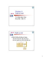
calculate the modulus of elasticity, E aac. After completing this
second loading cycle, remove the compressometer and load the
specimen to failure. The complete loading cycle is illustrated in
Fig. 3.
9.3.3.5 Take all readings under the final loading cycle (Fig.
3).
9.3.3.6 Convert each measure applied compressive load
(force) to compressive stress using the formula:
9.2.2 Number and Orientation—A test set shall consist of
three specimens. Whenever possible one specimen shall be
prepared for the upper third of the product, one from the
middle third, and one from the bottom third as determined by
the direction of rising of the mass during manufacturing.
Prepare the specimens so that the loading is applied to the
100-mm (4-in.) by 100-mm (4-in.) surface and is perpendicular
to the direction of rising during manufacture.
9.2.3 Preparation—Dry the specimens to a moisture content between 5 and 15 % by weight. After drying and before
testing, store the specimens at room temperature until they
reach an equilibrium temperature. Prepare the loadbearing
surfaces in accordance with 6.2.3.
9.3 Test Procedure—The test procedure shall be as follows:
9.3.1 Determination of Density and Moisture Content—
Determine the dry density of comparable specimens and the
moisture content of the test specimens according to Specification C1692.
9.3.2 Determination of Compressive Strength—Using companion specimens, determine the compressive strength in
accordance with Test Method C39/C39M.
9.3.3 Determination of Modulus of Elasticity in Compression:
9.3.3.1 Place the uncapped specimen in the testing machine
so that the 100-mm (4-in.) by 100-mm (4-in.) surfaces are
loaded. Determine and record the dimensions of the loaded
surfaces with a precision of 60.12 in. (63 mm). No overall
unit dimension (width, height, and length) shall differ by more
than (0.125 in. (3 mm) from the specified dimension.
9.3.3.2 Attach electrical resistance strain gauges or mechanical compressometers to two opposite longitudinal surfaces of the specimen. Place the strain gauges within the
middle third of the specimen, as close as possible to the center.
When using compressometers, the gauge length shall be 4 6
0.08 in. (100 6 2 mm), and the compressometers shall be
centered about the middle third of the specimen.
F
f5A
c
5
(7)
C1693 – 11
FIG. 3 Modulus of Elasticity Loading Cycle Diagram
9.4.1 The moisture content and dry density of the material,
9.4.2 Identification number of the specimen,
9.4.3 Average width of specimen to the nearest 1.0 mm,
9.4.4 Average depth of specimen to the nearest 1.0 mm,
9.4.5 Mass of specimen, kg (lb),
9.4.6 Maximum applied load, N (lbf),
9.4.7 Modulus of Elasticity, MPa (psi),
9.4.8 Defects in specimen,
9.4.9 Description of failure,
9.4.10 AAC grade,
9.4.11 Compressive strength of AAC, MPa (psi), and
9.4.12 Dry Bulk Density of AAC, kg/m3(pcf).
where:
f
= calculated applied stress, MPa (psi),
F = measured applied compressive load, N (lbf), and
Ac = area over which the load is applied, mm2(in.2).
9.3.3.7 If strain gauges are used, record the strain directly. If
compressometers are used, calculate the compressive strain, ´,
as follows:
Da 1 Db
2
´5 L
m
(8)
where:
Da and Db = the change in gage length, and
= gauge lengths.
Lm
9.3.3.8 Determine the modulus of elasticity, Ec,:
f b – fa
Ec 5 ´ – ´
b
10. Precision and Bias
(9)
10.1 The precision and bias of the test procedures described
in Sections 6 to 9 are being determined and will be provided
when sufficient data are available to indicate acceptable tolerances in repeatability and reproducibility.
a
where:
fa = stress recorded at 0.05 f’AAC,
fb = stress recorded at 0.33 f’ AAC,
´a = average strain calculated at 0.05 f’AAC, and
´b = average strain calculated at 0.33 f’AAC.
9.4 Report —Prepare the report in conformance with Practice E575, and include the following:
11. Keywords
11.1 AAC; autoclaved aerated concrete; compressive
strength; density; moisture content; shrinkage
6
C1693 – 11
ASTM International takes no position respecting the validity of any patent rights asserted in connection with any item mentioned
in this standard. Users of this standard are expressly advised that determination of the validity of any such patent rights, and the risk
of infringement of such rights, are entirely their own responsibility.
This standard is subject to revision at any time by the responsible technical committee and must be reviewed every five years and
if not revised, either reapproved or withdrawn. Your comments are invited either for revision of this standard or for additional standards
and should be addressed to ASTM International Headquarters. Your comments will receive careful consideration at a meeting of the
responsible technical committee, which you may attend. If you feel that your comments have not received a fair hearing you should
make your views known to the ASTM Committee on Standards, at the address shown below.
This standard is copyrighted by ASTM International, 100 Barr Harbor Drive, PO Box C700, West Conshohocken, PA 19428-2959,
United States. Individual reprints (single or multiple copies) of this standard may be obtained by contacting ASTM at the above
address or at 610-832-9585 (phone), 610-832-9555 (fax), or (e-mail); or through the ASTM website
(www.astm.org). Permission rights to photocopy the standard may also be secured from the ASTM website (www.astm.org/
COPYRIGHT/).
7