C1581 04
Bạn đang xem bản rút gọn của tài liệu. Xem và tải ngay bản đầy đủ của tài liệu tại đây (243.81 KB, 6 trang )
Designation: C 1581 – 04
Standard Test Method for
Determining Age at Cracking and Induced Tensile Stress
Characteristics of Mortar and Concrete under Restrained
Shrinkage1
This standard is issued under the fixed designation C 1581; the number immediately following the designation indicates the year of
original adoption or, in the case of revision, the year of last revision. A number in parentheses indicates the year of last reapproval. A
superscript epsilon (e) indicates an editorial change since the last revision or reapproval.
C 387 Specification for Packaged Dry, Combined Materials
for Mortar and Concrete
C 595 Specification for Blended Hydraulic Cements
C 1157 Performance Specification for Hydraulic Cement
C 1437 Test Method for Flow of Hydraulic Cement Mortar
F 441 Specification for Chlorinated Poly (Vinyl Chloride)
(CPVC) Plastic Pipe, Schedules 40 and 80
2.2 ASME Standards:3
B 46.1 Surface Texture (Surface Roughness, Waviness and
Lay)
1. Scope
1.1 This test method covers the laboratory determination of
the age at cracking and induced tensile stress characteristics of
mortar or concrete specimens under restrained shrinkage. The
procedure can be used to determine the effects of variations in
the proportions and material properties of mortar or concrete
on cracking due to both drying shrinkage and deformations
caused by autogenous shrinkage and heat of hydration.
1.2 This test method is not intended for expansive materials.
1.3 The values stated in inch-pound units are to be regarded
as standard. The values shown in parenthesis are in SI units and
are given for information only.
1.4 This standard does not purport to address all of the
safety concerns, if any, associated with its use. It is the
responsibility of the user of this standard to establish appropriate safety and health practices and to determine the
applicability of regulatory limitations prior to use.
(Warning—Fresh hydraulic cementitious mixtures are caustic
and may cause chemical burns to skin and tissue upon
prolonged exposure.)
3. Summary of Test Method
3.1 A sample of freshly mixed mortar or concrete is compacted in a circular mold around an instrumented steel ring.
The compressive strain developed in the steel ring caused by
the restrained shrinkage of the mortar or concrete specimen is
measured from the time of casting (1-6)4. Cracking of the test
specimen is indicated by a sudden decrease in the steel ring
strain. The age at cracking and the rate of tensile stress
development in the test specimen are indicators of the material’s resistance to cracking under restrained shrinkage.
2. Referenced Documents
2.1 ASTM Standards: 2
C 33 Specification for Concrete Aggregates
C 138/C 138 M Test Method for Density (Unit Weight),
Yield and Air Content (Gravimetric) of Concrete
C 143/C 143 M Test Method for Slump of HydraulicCement Mortar
C 150 Specification for Portland Cement
C 171 Specification for Sheet Materials for Curing Concrete
C 192/C 192 M Practice for Making and Curing Concrete
Test Specimens in the Laboratory
4. Significance and Use
4.1 This test method is for relative comparison of materials
and is not intended to determine the age at cracking of mortar
or concrete in any specific type of structure, configuration, or
exposure.
4.2 This test method is applicable to mixtures with aggregates of 0.5-in. (13-mm) maximum nominal size or less.
4.3 This test method is useful for determining the relative
likelihood of early-age cracking of different cementitious
mixtures and for aiding in the selection of cement-based
materials that are less likely to crack under retrained shrinkage.
Actual cracking tendency in service depends on many variables
1
This test method is under the jurisdiction of ASTM Committee C09 on
Concrete and Concrete Aggregates and is the direct responsibility of Subcommittee
C09.68 on Volume Change.
Current edition approved July 1, 2004. Published August 2004.
2
For referenced ASTM standards, visit the ASTM website, www.astm.org, or
contact ASTM Customer Service at For Annual Book of ASTM
Standards volume information, refer to the standard’s Document Summary page on
the ASTM website.
3
Available from American Society of Mechanical Engineers, 22 Law Drive,
Fairfield, NJ 07007-2900.
4
The boldface numbers in parenthesis refer to the list of references at the end of
this test method
Copyright © ASTM International, 100 Barr Harbor Drive, PO Box C700, West Conshohocken, PA 19428-2959, United States.
1
C 1581 – 04
6.1.2 Aggregates—Aggregates shall conform to Specification C 33. The maximum nominal size of the coarse aggregate
shall be 0.5-in. (13-mm) or less.
6.2 Mixing:
6.2.1 Concrete mixtures—Machine mix the concrete as
prescribed in Practice C 192/C 192M.
6.2.2 Mortar mixtures—Mix the mortar as prescribed in
Specification C 387.
including type of structure, degree of restraint, rate of property
development, construction and curing methods, and environmental conditions.
4.4 This test method can be used to determine the relative
effects of material variations on induced tensile stresses and
cracking potential. These variations can include, but are not
limited to, aggregate source, aggregate gradation, cement type,
cement content, water content, supplementary cementing materials, or chemical admixtures.
4.5 For materials that have not cracked during the test, the
rate of tensile stress development at the time the test is
terminated provides a basis for comparison of the materials.
7. Properties of Fresh Mixtures
7.1 Concrete mixtures—Samples of freshly mixed concrete
shall be tested in accordance with the following methods:
7.1.1 Density (unit weight) and air content—Test Method
C 138/C 138M.
7.1.2 Slump—Test Method C 143/C 143M.
7.2 Mortar mixtures—Samples of freshly mixed mortar
shall be tested in accordance with the following methods:
7.2.1 Density—Specification C 387.
7.2.2 Flow—Test Method C 1437.
5. Apparatus
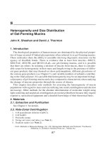
5.1 Steel ring—Structural steel pipe with a wall thickness of
0.50 6 0.05 in. (13 6 0.12 mm), an outside diameter of 13.0
6 0.12 in. (330 6 3.3 mm) and a height of 6.0 6 0.25 in. (152
6 6 mm) (see Fig. 1). Machine the inner and outer faces to
produce smooth surfaces with a texture of 63 microinches (1.6
micrometres) or finer, as defined in ASME B 46.1.
5.2 Strain gages—As a minimum, use two electrical resistance strain gages to monitor the strain development in the steel
ring. Each strain gage shall be wired in a quarter-bridge
configuration (that is, one leg of a full Wheatstone bridge). See
Note 1 for additional information.
5.3 Data acquisition system—The data acquisition system
shall be compatible with the strain instrumentation and automatically record each strain gage independently. The resolution
of the system shall be 60.0000005 in./in. (m/m). The system
shall be capable of recording strain data at intervals not to
exceed 30 minutes.
8. Specimen Fabrication and Test Setup
8.1 Bond two strain gages at midheight locations on the
interior surface of the steel ring along a diameter; that is, mount
the second gage diametrically opposite the first gage. Orient
the gages to measure strain in the circumferential direction.
Follow the manufacturer’s procedures for mounting and waterproofing the gages on the steel ring and connecting leadwires to the strain gage tabs.
8.2 Test specimen mold—The test specimen mold consists
of a base, an inner steel ring and an outer ring.
8.2.1 Fabricate a base for each test specimen as described in
Section 5.4. The top surface of each base shall minimize
frictional restraint of the specimen.
NOTE 1—Use of a precision resistor, to balance the leg of the bridge, a
strain conditioner input module, to complete the other half of the bridge,
and a 16-channel interface board has been found to adequately provide the
required resolution of the system.
NOTE 2—Use of an epoxy coating or a Mylar sheet covering has been
found to provide a suitable surface between the test specimen and the
base.
5.4 Base—Epoxy-coated plywood or other non-absorptive
and non-reactive surface.
5.5 Outer ring—Use one of the following alternative materials as the outer ring.
5.5.1 PVC pipe—Schedule 80-18 PVC pipe, in accordance
with Specification F 441, with a 16.0 6 0.12-in. (406 6 3-mm)
inside diameter and 6.0 6 0.25-in. (152 6 6-mm) height (see
Fig. 1).
5.5.2 Steel outer ring—0.125-in. (3-mm) thick steel sheeting formed to obtain a 16.0 6 0.12-in. (406 6 3-mm) inside
diameter and 6.0 6 0.25-in. (152 6 6-mm) height.
5.5.3 Other materials—Other suitable non-absorptive and
non-reactive materials formed to obtain a 16.0 6 0.12-in. (406
6 3-mm) inside diameter and 6.0 6 0.25-in. (152 6 6-mm)
height.
5.6 Testing environment—Store the specimens in an environmentally controlled room with constant air temperature of
73.5 6 3.5 °F (23.0 6 2.0 °C) and relative humidity of 50 6
4 %.
8.2.2 Secure the steel ring to the base before casting using
bolts with eccentric washers (see Fig. 1).
8.2.2.1 Coat the outer surface of the steel ring with a release
agent.
8.2.3 Coat the inner surface of the outer ring with a release
agent.
8.2.4 Secure the outer ring to the base to complete the test
specimen mold using bolts with eccentric washers. Maintain a
1.50 6 0.12-in. (38 6 3-mm) space between the inner steel
ring and the outer ring (see Fig. 1).
8.3 Make and cure at least three test specimens for each
material and test condition following the applicable requirements of Practice C 192/C 192 M. In making a specimen, place
the test specimen mold on a vibrating table, fill the mold in two
approximately equal layers, rod each layer 75 times using a
3⁄8-in. (10-mm) diameter rod, and vibrate each layer to consolidate the mixture.
8.4 Strike-off the test specimen surface after consolidation.
Finish with the minimum manipulation necessary to achieve a
flat surface. Remove any fresh concrete or mortar that has
spilled inside the steel ring or outside the outer ring so that the
6. Materials and Mixing
6.1 Materials:
6.1.1 Cement—Cement shall conform to Specifications
C 150, C 595, or C 1157.
2
C 1581 – 04
FIG. 1 Test specimen dimensions (top), specimen mold (bottom left), and specimen (bottom right).
base is clean. Transfer the test specimens to the testing
environment within 10 minutes after completion of casting.
8.5 Upon transfer of the test specimens to the testing
environment, immediately loosen the bolts with eccentric
washers and rotate the washers so they are not in contact with
the steel ring and outer ring. Within 2 minutes after loosening
the bolts with eccentric washers, connect the strain gage
lead-wires to the data acquisition system, record the time, and
begin monitoring the strain gages at intervals not greater than
30 minutes. Ensure that the strain gage connecting wires are
3
C 1581 – 04
clean of loose material before making the connections. The
time of the first strain measurement is taken as zero age of the
specimen.
8.7.4 For the calculations outlined subsequently, the age
when drying is initiated is the time when the first strain reading
is made after the test specimens have been sealed.
NOTE 3—Monitoring the strain gages soon after casting provides
information on the internal deformations caused by autogenous shrinkage
and heat of hydration (4).
9. Measurement Procedure
9.1 Record the time at the start of strain monitoring as stated
in Section 8.5.
9.2 Record ambient temperature and relative humidity of
the testing environment every day.
9.3 Monitor the strains in the steel rings at intervals not to
exceed 30 minutes, recording the output of each strain gage
separately with the data acquisition system. Record both the
time and the strain at each measurement. A sudden decrease in
compressive strain in one or both strain gages indicates
cracking (see Note 6) (1-5). Review the strain measurements
and visually inspect the specimens for cracking at time
intervals not greater than 3 days.
8.6 Curing—Unless otherwise specified, test specimens
shall be moist cured in the molds for 24 h at 73.5 6 3.5 °F
(23.0 6 2.0 °C) using wet burlap covered with polyethylene
film meeting the requirements of Specification C 171. Begin
the curing process within 5 minutes after the first strain
reading. If the curing period is longer than 24 h, remove the
outer ring at 24 h and continue the curing process.
8.7 At the end of curing and between strain measurements,
prepare the test specimens for drying as follows. Complete the
test specimen preparation within 15 minutes.
8.7.1 Remove the outer ring, if it is still in place, and/or
remove the polyethylene film and burlap.
8.7.2 Gently remove loose material, if present, from the top
surface of the test specimen.
8.7.3 Seal the top surface of the test specimen using one of
the following alternative procedures.
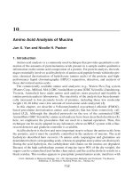
NOTE 6—The sudden decrease in compressive strain at cracking is
usually greater than 30 microstrains (see Fig. 2).
9.4 Monitor and record the strain in the steel rings for at
least 28 days after initiation of drying, unless cracking occurs
prior to 28 days.
9.5 Plot the steel ring strain for each strain gage against
specimen age (see Fig. 2).
NOTE 4—With the top surface sealed, and the specimen resting on its
base, the test specimen dries from the outer circumferential surface only.
8.7.3.1 Paraffın wax—Coat the top surface of the test
specimen with molten paraffin wax. Take precautions to ensure
that the outer circumference of the test specimen is not coated
with the paraffin wax.
10. Calculation
10.1 Age at cracking—Determine the age at cracking as the
age of each test specimen (measured from the time of casting)
when a sudden decrease in strain occurs. Report the age at
cracking to the nearest 0.25 day. If a test specimen does not
crack within the duration of the test, report the result as “no
cracking” and record the age when the test was terminated.
10.1.1 Average age at cracking—Calculate the average age
at cracking for the test specimens to the nearest day.
NOTE 5—Use of a 1.5-in. (38-mm) wide brush has been found to be an
appropriate means of applying the paraffin wax to the top surface of the
test specimens.
8.7.3.2 Adhesive aluminum-foil tape—Seal the top surface
of the test specimen with adhesive aluminum-foil tape.
FIG. 2 Steel ring strain versus specimen age.
4
C 1581 – 04
10.2 Initial strain—From the time-strain data for each strain
gage, record the initial strain as the strain corresponding to the
age when drying was initiated (see Fig. 2).
10.2.1 Average initial strain—Calculate the average initial
strain for the test specimens.
where:
q
= stress rate in each test specimen, psi/day (MPa/
day),
G
= 10.47 3 106 psi (72.2 GPa),
|aavg| = absolute value of the average strain rate factor for
each test specimen, (in./in.)/day1/2 ((m/m)/day1/2),
and
= elapsed time at cracking or elapsed time when the
tr
test is terminated for each test specimen, days
NOTE 7—The average initial strain indicates the net effect of deformations caused by early-age autogenous shrinkage and heat of hydration
under the restrained conditions (4).
10.3 Maximum strain—From the time-strain data for each
strain gage on each test specimen, record the maximum strain
as the strain corresponding to the age at cracking or the age
when the test is terminated.
10.3.1 When cracking occurs, the maximum strain is the
strain value just prior to the sudden decrease in strain (see Fig.
2).
10.4 Average maximum strain, emax—Calculate the average
maximum strain for the test specimens.
NOTE 10—G in Eq 2 is a constant based on the ring dimensions used in
this test method (1-4).
10.5.6 Average stress rate, S—Calculate the average stress
rate for the test specimens to the nearest psi/day (0.01
MPa/day).
11. Report
Record in the report the following data as pertinent to the
variables studied:
11.1 Properties of the material being tested: mixture proportions, air content, slump and density of concrete mixtures, and
mixture proportions, flow, and density of mortar mixtures.
11.2 Type and duration of curing;
11.3 Daily ambient temperature and relative humidity data
for the test environment;
11.4 Plots of steel ring strain vs. specimen age for each test
specimen;
11.5 Average age at cracking;
11.6 Age when the test was terminated for specimens that
have not cracked during the test;
11.7 Average initial strain;
11.8 Average maximum strain;
11.9 Plots of net strain vs. square root of elapsed time for
each specimen; and
11.10 Average stress rate at cracking or at the time the test
was terminated.
NOTE 8—The average maximum strain relates to the magnitude of
stress buildup in the material under the conditions of restraint provided in
this test method.
10.5 Stress rate, S—For the test material, use the following
procedure to calculate the rate of tensile stress development
that corresponds to the age at cracking or the age when the test
is terminated (see Section 4.5).
10.5.1 Elapsed time, t—Calculate the elapsed time for each
test specimen as the difference between each recorded time and
the age drying was initiated.
10.5.2 Net strain—For each strain gage on the test specimen, calculate the net strain at each recorded time, starting
from the age drying was initiated, as the difference between the
strain in the steel ring at each recorded time and the initial
strain.
10.5.3 Strain rate factor, a—Plot the net strain against the
square root of elapsed time for each strain gage on the test
specimen and use linear regression analysis to fit a straight line
through the data. The strain rate factor is the slope of the line
(see Eq 1):
enet 5 a =t 1 k
12. Precision and Bias
12.1 Precision—The precision of this test method has not
been determined. The single laboratory repeatability standard
deviation of the age at cracking is 2 days. The single laboratory
repeatability standard deviation of the stress rate at cracking is
4 psi/day (0.03 MPa/day) for materials with an average stress
rate equal to or less than 40 psi/day (0.28 MPa/day). The single
laboratory repeatability standard deviation of the stress rate at
cracking is 11 psi/day (0.08 MPa/day) for materials with an
average stress rate greater than 40 psi/day (0.28 MPa/day) (3).
12.2 Bias—No statement on bias is being made since there
is no accepted reference material suitable for determining the
bias of these procedures.
(1)
where:
enet = net strain, in./in. (m/m),
a
= strain rate factor for each strain gage on the test
specimen (in./in.)/day1/2 ((m/m)/day1/2),
t
= elapsed time, days, and
k
= regression constant
NOTE 9—The square root function has been found to consistently
provide a good fit to the test data (3).
10.5.4 Average strain rate factor, aavg—Calculate the average strain rate factor for each test specimen.
10.5.5 Stress rate, q—Calculate the stress rate in each test
specimen at cracking or at the time the test is terminated (3):
q5
G |aavg|
2=tr
13. Keywords
13.1 Cracking; restrained shrinkage; ring test; shrinkage;
tensile stress.
(2)
5
C 1581 – 04
APPENDIX
(Nonmandatory Information)
X1. Interpretation of Results
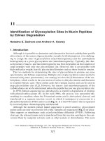
TABLE X1.1 Potential for cracking classification
Net Time-to-Cracking,
tcr, days
Average Stress Rate, S
(psi/day)
Average Stress Rate, S
(MPa/day)
Potential for
Cracking
0 < tcr # 7
7 < tcr # 14
14 tcr # 28
tcr > 28
S $ 50
25 # S < 50
15 # S < 25
S < 15
S $ 0.34
0.17 # S < 0.34
0.10 # S < 0.17
S < 0.10
High
Moderate-High
Moderate-Low
Low
X1.1 Net Time-to-cracking, tcr—Calculate the net time-tocracking for the material as the difference between the age at
cracking and the age drying was initiated. Note that if a test
material cracks during the period of curing (that is, before
drying is initiated), the net time-to-cracking is zero.
X1.2.1 The net time-to-cracking classification in Table X1.1
can be used to assess the relative performance of materials that
crack during the test.
X1.2.2 For materials with average stress rates lower than 15
psi/day (0.10 MPa/day) that have not cracked during the test,
the magnitudes of average stress rate can be compared to assess
the relative potential for cracking. This allows for an appropriate comparison of materials where time constraint does not
permit testing to be carried out until cracking occurs.
X1.2 Potential for cracking—A classification table for
cracking potential based on the net time-to-cracking and the
average stress rate at cracking or at the time the test is
terminated is provided to aid in the comparison of materials
(3).
REFERENCES
(1) See, H. T., Attiogbe, E. K. and Miltenberger, M. A., “Shrinkage
Cracking Characteristics of Concrete Using Ring Specimens,” ACI
Materials Journal, V. 100, No. 3, May-June 2003, pp. 239-245.
(2) Attiogbe, E. K., See, H. T. and Miltenberger, M. A., “Tensile Creep in
Restrained Shrinkage,” Creep, Shrinkage and Durability Mechanics of
Concrete and other Quasi-Brittle Materials, Proceedings of the Sixth
International Conference, F.J. Ulm, Z.P. Bazant and F.H. Wittmann
(eds.), Elsevier Science, Aug. 2001, pp. 651-656.
(3) See, H. T., Attiogbe, E. K. and Miltenberger, M. A., “Potential for
Restrained Shrinkage Cracking of Concrete and Mortar,” Proceedings
of the ASTM Symposium on Early-Age Cracking of Concrete, Dec.
2003.
(4) Hossain A. B., Pease B. and Weiss W. J., “Quantifying Early-Age
Stress Development and Cracking in Low w/c Concrete Using the
Restrained Ring Test with Acoustic Emission,” Proceedings of the
82nd Annual Meeting of the Transportation Research Board, 2003.
(5) Whiting, D. A., Detwiler, R. J. and Lagergren, E. S., “Cracking
Tendency and Drying Shrinkage of Silica Fume Concrete for Bridge
Deck Applications,” ACI Materials Journal, V. 97, No. 1, JanuaryFebruary 2000, pp. 71-77.
(6) Grzybowski, M. and Shah, S. P., “Shrinkage Cracking of Fiber
Reinforced Concrete,” ACI Materials Journal, V. 87, No. 2, MarchApril 1990, pp. 138-148.
ASTM International takes no position respecting the validity of any patent rights asserted in connection with any item mentioned
in this standard. Users of this standard are expressly advised that determination of the validity of any such patent rights, and the risk
of infringement of such rights, are entirely their own responsibility.
This standard is subject to revision at any time by the responsible technical committee and must be reviewed every five years and
if not revised, either reapproved or withdrawn. Your comments are invited either for revision of this standard or for additional standards
and should be addressed to ASTM International Headquarters. Your comments will receive careful consideration at a meeting of the
responsible technical committee, which you may attend. If you feel that your comments have not received a fair hearing you should
make your views known to the ASTM Committee on Standards, at the address shown below.
This standard is copyrighted by ASTM International, 100 Barr Harbor Drive, PO Box C700, West Conshohocken, PA 19428-2959,
United States. Individual reprints (single or multiple copies) of this standard may be obtained by contacting ASTM at the above
address or at 610-832-9585 (phone), 610-832-9555 (fax), or (e-mail); or through the ASTM website
(www.astm.org).
6