Bs en 1097 2
Bạn đang xem bản rút gọn của tài liệu. Xem và tải ngay bản đầy đủ của tài liệu tại đây (296.66 KB, 23 trang )
British Standard
Licensed Copy: Akin Koksal, Bechtel Ltd, 10 December 2002, Uncontrolled Copy, (c) BSI
A single copy of this British Standard is licensed to
Akin Koksal
10 December 2002
This is an uncontrolled copy. Ensure use of the most
current version of this document by searching British
Standards Online at bsonline.techindex.co.uk
BRITISH STANDARD
Tests for mechanical and
physical properties of
aggregates Ð
Licensed Copy: Akin Koksal, Bechtel Ltd, 10 December 2002, Uncontrolled Copy, (c) BSI
Part 2: Methods for the determination of
resistance to fragmentation
The European Standard EN 1097-2:1998 has the status of a
British Standard
ICS 91.100.20
NO COPYING WITHOUT BSI PERMISSION EXCEPT AS PERMITTED BY COPYRIGHT LAW
|
|
|
|
|
|
|
|
|
|
|
|
|
|
|
|
|
|
|
|
|
|
|
|
|
|
|
|
|
|
|
|
|
|
|
|
|
|
|
|
|
|
|
|
|
|
|
|
|
|
|
|
|
|
|
|
|
|
|
|
|
|
|
|
|
|
|
|
|
|
|
|
|
|
|
|
|
|
|
|
|
|
|
|
|
|
|
|
|
|
|
|
|
|
|
|
|
|
|
|
|
|
|
|
|
|
|
|
|
|
|
|
|
|
|
|
|
|
|
|
|
|
|
|
|
|
|
|
|
BS EN
1097-2:1998
BS EN 1097-2:1998
National foreword
This British Standard is the English language version of EN 1097-2:1998. It is
included in a package of European Standards declared by CEN/TC 154 and it will
supersede BS 812-110:1990, BS 812-111:1990 and BS 812-112:1990 which, it is
intended, will be withdrawn on 1999-12-01 if all the European Standards included in
the package are available.
The UK participation in its preparation was entrusted by Technical Committee
B/502, Aggregates, to Subcommittee B/502/6, Test methods, which has the
responsibility to:
Ð aid enquirers to understand the text;
Ð present to the responsible European committee any enquiries on the
interpretation, or proposals for change, and keep the UK interests informed;
Ð monitor related international and European developments and promulgate
them in the UK.
A list of organizations represented on this committee can be obtained on request to
its secretary.
Licensed Copy: Akin Koksal, Bechtel Ltd, 10 December 2002, Uncontrolled Copy, (c) BSI
Cross-references
The British Standards which implement international or European publications
referred to in this document may be found in the BSI Standards Catalogue under the
section entitled ªInternational Standards Correspondence Indexº, or by using the
ªFindº facility of the BSI Standards Electronic Catalogue.
A British Standard does not purport to include all the necessary provisions of a
contract. Users of British Standards are responsible for their correct application.
Compliance with a British Standard does not of itself confer immunity
from legal obligations.
Summary of pages
This document comprises a front cover, an inside front cover, the EN title page,
pages 2 to 18, an inside back cover and a back cover.
This British Standard, having
been prepared under the
direction of the Sector Board for
Building and Civil Engineering,
was published under the
authority of the Standards Board
and comes into effect on
15 September 1998
BSI 1998
ISBN 0 580 30074 9
Amendments issued since publication
Amd. No.
Date
Text affected
EN 1097-2
EUROPEAN STANDARD
NORME EUROPÊENNE
EUROPẰISCHE NORM
April 1998
ICS 91.100.20
Descriptors: aggregates, tests, physical properties, mechanical properties, mechanical strength, fragmentation
English version
Licensed Copy: Akin Koksal, Bechtel Ltd, 10 December 2002, Uncontrolled Copy, (c) BSI
Tests for mechanical and physical properties of aggregates Ð
Part 2: Methods for the determination of resistance to fragmentation
Essais pour deÂterminer les caracteÂristiques
meÂcaniques et physiques des granulats Ð
Partie 2: MeÂthodes pour la deÂtermination de la
reÂsistance aÁ la fragmentation
PruÈfverfahren fuÈr mechanische und physikalische
Eigenschaften von GesteinskoÈrnungen Ð
Teil 2: Verfahren zur Bestimmung des widerstandes
gegen ZertruÈmmerung
This European Standard was approved by CEN on 25 March 1998.
CEN members are bound to comply with the CEN/CENELEC Internal Regulations
which stipulate the conditions for giving this European Standard the status of a
national standard without any alteration. Up-to-date lists and bibliographical
references concerning such national standards may be obtained on application to
the Central Secretariat or to any CEN member.
This European Standard exists in three official versions (English, French, German).
A version in any other language made by translation under the responsibility of a
CEN member into its own language and notified to the Central Secretariat has the
same status as the official versions.
CEN members are the national standards bodies of Austria, Belgium, Czech
Republic, Denmark, Finland, France, Germany, Greece, Iceland, Ireland, Italy,
Luxembourg, Netherlands, Norway, Portugal, Spain, Sweden, Switzerland and
United Kingdom.
CEN
European Committee for Standardization
Comite EuropeÂen de Normalisation
EuropaÈisches Komitee fuÈr Normung
Central Secretariat: rue de Stassart 36, B-1050 Brussels
1998 CEN All rights of exploitation in any form and by any means reserved worldwide for CEN national
Members.
Ref. No. EN 1097-2:1998 E
Page 2
EN 1097-2:1998
Licensed Copy: Akin Koksal, Bechtel Ltd, 10 December 2002, Uncontrolled Copy, (c) BSI
Foreword
This European Standard has been prepared by
Technical Committee CEN/TC 154, Aggregates, the
Secretariat of which is held by BSI.
This standard forms part of a series of tests for
mechanical and physical properties of aggregates. Test
methods for other properties of aggregates will be
covered by parts of the following European Standards:
EN 932, Tests for general properties of aggregates.
EN 933, Tests for geometrical properties of aggregates.
EN 1367, Tests for thermal and weathering properties
of aggregates.
EN 1744, Tests for chemical properties of aggregates.
prEN 13179, Tests for filler aggregate used in
bituminous bound fillers.
The other parts of EN 1097 will be:
EN 1097-1, Tests for mechanical and physical
properties of aggregates Ð Part 1: Determination of
the resistance to wear (micro-Deval).
EN 1097-3, Tests for mechanical and physical
properties of aggregates Ð Part 3: Determination of
loose bulk density and voids.
prEN 1097-4, Tests for mechanical and physical
properties of aggregates Ð Part 4: Determination of
the voids of dry compacted filler.
prEN 1097-5, Tests for mechanical and physical
properties of aggregates Ð Part 5: Determination of
the water content by drying in a ventilated oven.
prEN 1097-6, Tests for mechanical and physical
properties of aggregates Ð Part 6: Determination of
particle density and water absorption.
prEN 1097-7, Tests for mechanical and physical
properties of aggregates Ð Part 7: Determination of
the particle density of filler Ð Pyknometer method.
prEN 1097-8, Tests for mechanical and physical
properties of aggregates Ð Part 8: Determination of
the polished stone value.
EN 1097-9, Tests for mechanical and physical
properties of aggregates Ð Part 9: Method for the
determination of the resistance to wear by abrasion
from studded tyres: Nordic test.
prEN 1097-10, Tests for mechanical and physical
properties of aggregates Ð Part 10: Water suction
height.
This European Standard shall be given the status of a
national standard, either by publication of an identical
text or by endorsement, at the latest by October 1998,
and conflicting national standards shall be withdrawn
at the latest by December 1999.
According to the CEN/CENELEC Internal Regulations,
the national standards organizations of the following
countries are bound to implement this European
Standard: Austria, Belgium, Czech Republic, Denmark,
Finland, France, Germany, Greece, Iceland, Ireland,
Italy, Luxembourg, Netherlands, Norway, Portugal,
Spain, Sweden, Switzerland and the United Kingdom.
Contents
Foreword
1
Scope
2
Normative references
3
Definitions
4
Apparatus
5
Determination of resistance to
fragmentation by the Los Angeles test
method
5.1 Principle
5.2 Preparation of the sample for testing
5.3 Test procedure
5.4 Calculation and expression of results
5.5 Test report
6
Determination of resistance to
fragmentation by the impact test
method
6.1 Principle
6.2 Preparation of the sample for testing
6.3 Test procedure
6.4 Calculation and expression of results
6.5 Test report
Annex A (informative) Alternative narrow
range classifications
Annex B (informative) The impact tester:
constructional, operational and safety
requirements
Annex C (informative) Checking of the
impact tester
Annex D (informative) Precision
Annex E (informative) Worked example of
calculation of impact value, SZ
Annex F (informative) Bibliography
Page
2
3
3
3
3
5
5
5
5
5
5
5
5
5
6
6
6
7
7
15
17
17
18
BSI 1998
Page 3
EN 1097-2:1998
1 Scope
This European Standard specifies procedures for the
determination of the resistance of coarse aggregate to
fragmentation. Two methods are defined:
a) the Los Angeles test (reference method);
b) the impact test (alternative method).
NOTE The impact test can be used as an alternative to the Los
Angeles test but a correlation with the Los Angeles test should
first be established to avoid double testing and ensure mutual
recognition of results. The Los Angeles test (reference method)
should be used in cases of dispute.
This European Standard applies to natural or artificial
aggregates used in building and civil engineering.
Licensed Copy: Akin Koksal, Bechtel Ltd, 10 December 2002, Uncontrolled Copy, (c) BSI
2 Normative references
This European Standard incorporates by dated or
undated reference, provisions from other publications.
These normative references are cited at the
appropriate places in the text and the publications are
listed hereafter. For dated references, subsequent
amendments to or revisions of any of these
publications apply to this European Standard only
when incorporated in it by amendment or revision. For
undated references, the latest edition of the publication
referred to applies.
EN 932-1:1996, Tests for general properties of
aggregates Ð Part 1: Methods for sampling.
prEN 932-2, Tests for general properties of
aggregates Ð Part 2: Methods for reducing laboratory
samples.
prEN 932-5, Tests for general properties of
aggregates Ð Part 5: Common equipment and
calibration.
EN 933-1:1997, Tests for geometrical properties of
aggregates Ð Part 1: Determination of particle size
distribution Ð Sieving method.
EN 933-2: 1995, Tests for geometrical properties of
aggregates Ð Part 2: Determination of particle size
distribution Ð Test sieves, nominal size of apertures.
prEN 1097-6, Tests for mechanical and physical
properties of aggregates Ð Part 6: Determination of
particle density and water absorption.
EN 10025:1993, Hot rolled products of non-alloy
structural steels Ð Technical delivery conditions
(includes amendment A1:1993).
3 Definitions
For the purposes of this standard the following
definitions apply.
3.1
Los Angeles coefficient, LA
the percentage of the test portion passing a 1,6 mm
sieve after completion of the test
BSI 1998
3.2
impact value
the value SZ which gives a measure of the resistance
of aggregates to dynamic crushing; it is equal to one
fifth of the sum of the mass percentages of the tested
sample passing through five specified test sieves when
tested in accordance with clause 6
3.3
test specimen
the sample used in a single determination when a test
method requires more than one determination of a
property
3.4
test portion
the sample used as a whole in a single test
3.5
laboratory sample
a reduced sample derived from a bulk sample for
laboratory testing
3.6
constant mass
successive weighings after drying at least 1 h apart not
differing by more than 0,1 %
NOTE In many cases constant mass can be achieved after a test
portion has been dried for a pre-determined period in a specified
oven (see 4.1.3) at (110 ± 5) 8C. Test laboratories may determine
the time required to achieve constant mass for specific types and
sizes of sample dependent upon the drying capacity of the oven
used.
4 Apparatus
Unless otherwise stated, all apparatus shall conform to
the general requirements of prEN 932-5.
4.1 General apparatus
4.1.1 Test sieves, conforming to EN 933-2 with
aperture sizes as specified in Table 1.
4.1.2 Balance, capable of weighing the test portion to
an accuracy of 0,1 % of the mass of the test portion.
4.1.3 Ventilated oven, controlled to maintain a
temperature of (110 ± 5) 8C.
Table 1 Ð Test sieves
Test
Aperture size
mm
Los Angeles
1,6 10 11,2 (or 12,5) 14
Impact test (see NOTE)
0,2 0,63 2 5 8 10 11,2 12,5
NOTE For the impact test, because of the tolerances in the
sieve openings, the same 8 mm test sieve used for the
preparation of the test portion should again be used for the
evaluation of the test.
Page 4
EN 1097-2:1998
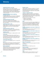
Internal length
(508 ± 5)
Internal diameter
(711 ± 5)
Shelf
Cover and
opening
Licensed Copy: Akin Koksal, Bechtel Ltd, 10 December 2002, Uncontrolled Copy, (c) BSI
Rotation
Dimensions in millimetres
Figure 1 Ð Typical Los Angeles testing machine
4.2 Additional apparatus required for the
determination of resistance to fragmentation by
the Los Angeles test method
4.2.1 Equipment, for reducing the laboratory sample
to a test portion, as described in prEN 932-2.
4.2.2 Los Angeles test machine, comprising the
following essential parts.
NOTE An example of a machine that has been found to be
satisfactory is shown in Figure 1.
4.2.2.1 Hollow drum, made of structural steel
plate (12+1
20,5) mm thick conforming to grade S275 of
EN 10025:1993 which has been selected to be formed
without undue stress, and can be welded without
significant distortion. The drum shall be closed at both
ends. It shall have an internal diameter of (711 ± 5) mm
and an internal length of (508 ± 5) mm. The drum shall
be supported on two horizontal stub axles fixed to its
two end walls but not penetrating inside the drum; the
drum shall be mounted so that it rotates about a
horizontal axis.
An opening (150 ± 3) mm wide shall be provided,
preferably over the whole length of the drum, to
facilitate insertion and removal of the sample after the
test. During the test, the opening shall be sealed so
that it is dustproof, by using a removable cover which
enables the inside surface to remain cylindrical.
The cylindrical inner surface shall be interrupted by a
projecting shelf, placed between 380 mm and 820 mm
from the nearest edge of the opening. The distance
shall be measured along the inside of the drum in the
direction of rotation. The shelf shall have a rectangular
cross-section (length equal to that of the drum,
width (90 ± 2) mm, thickness (25 ± 1) mm) and it shall
be placed in a diametrical plane, along a generating
line, and shall be rigidly fixed in place.
The shelf shall be replaced when its width at any point
wears to less than 86 mm and, its thickness at any
point along the front edge, wears to less than 23 mm.
The base of the machine shall be supported directly on
a level concrete or stone block floor.
NOTE The removable cover should be made of the same steel as
the drum. The projecting shelf should be made of the same steel
or a harder grade.
4.2.2.2 Ball load, consisting of 11 spherical steel balls,
each with a diameter of between 45 mm and 49 mm
(see annex A). Each ball shall weigh between 400 g
and 445 g, and the total load shall weigh
between 4 690 g and 4 860 g.
NOTE The nominal mass of the charge with new balls is 4 840 g.
A positive tolerance of 20 g allows for manufacturing variation and
a negative tolerance of 150 g allows for ball wear in use.
4.2.2.3 Motor, imparting a rotational speed to the
drum of between 31 r/min and 33 r/min.
4.2.2.4 Tray, for recovering the material and the ball
load after testing.
4.2.2.5 Revolution counter, which will automatically
stop the motor after the required number of
revolutions.
BSI 1998
Page 5
EN 1097-2:1998
4.3 Additional apparatus required for the
determination of resistance to fragmentation by
the impact test method
4.3.1 Impact tester, see annex B.
4.3.2 Equipment for testing the accuracy of the
impact tester, see annex C.
NOTE Annexes B and C are informative and do not contain any
normative provisions for the application of this European
Standard. However, it is strongly recommended that all the
informative provisions of these annexes are observed when
carrying out the test specified in clause 6.
4.3.3 Brush and bowls.
Licensed Copy: Akin Koksal, Bechtel Ltd, 10 December 2002, Uncontrolled Copy, (c) BSI
5 Determination of resistance to
fragmentation by the Los Angeles test
method
5.1 Principle
A sample of aggregate is rolled with steel balls in a
rotating drum. After rolling is complete, the quantity of
material retained on a 1,6 mm sieve is determined.
5.2 Preparation of the sample for testing
The mass of the sample sent to the laboratory shall
have at least 15 kg of particles in the 10 mm to 14 mm
size range.
The test shall be carried out on aggregate passing
the 14 mm test sieve and retained on the 10 mm test
sieve. In addition, the grading of the test portion shall
comply with one of the following requirements:
a) between 60 % and 70 % passing a 12,5 mm test
sieve; or
b) between 30 % and 40 % passing a 11,2 mm test
sieve.
NOTE The additional grading requirements allow the test portion
to be created from product sizes other than 10/14 (see annex A).
Sieve the laboratory sample using the 10 mm, 11,2 mm
(or 12,5 mm) and 14 mm test sieves to give separate
fractions in the ranges 10 mm to 11,2 mm (or 12,5 mm)
and 11,2 mm (or 12,5 mm) to 14 mm. Wash each
fraction separately, in accordance with clause 6 of
EN 933-1:1997, and dry them in the oven at (110 ± 5) 8C
to constant mass.
Allow the fractions to cool to ambient temperature.
Mix the two fractions to provide a modified 10 mm
to 14 mm laboratory sample which complies with the
appropriate additional grading requirement given
above.
Reduce the modified laboratory sample prepared from
the mixed fractions to test portion size in accordance
with prEN 932-2. The test portion shall have a mass of
(5 000 ± 5) g.
5.3 Test procedure
Check that the drum is clean before loading the
sample. Carefully place the balls in the machine, then
the test portion. Replace the cover and rotate the
machine for 500 revolutions, at a constant speed
between 31 r/min and 33 r/min.
Pour the aggregate into a tray placed under the
apparatus, taking care that the opening is just above
the tray in order to avoid losing any material. Clean
BSI 1998
out the drum, removing all fines, paying particular
attention around the projecting shelf. Carefully remove
the ball load from the tray, taking care not to lose any
aggregate particles.
Analyse the material from the tray in accordance with
EN 933-1:1997 by washing and sieving using
a 1,6 mm sieve. Dry the portion retained on the 1,6 mm
sieve at a temperature of (110 ± 5) 8C until a constant
mass is achieved.
5.4 Calculation and expression of results
Calculate the Los Angeles coefficient (LA), from the
following equation:
LA =
5 000 2 m
50
where
m is the mass retained on a 1,6 mm sieve, in
grams (g).
Report the result to the nearest whole number.
NOTE A statement on the precision of the Los Angeles test is
given in annex D.
5.5 Test report
The test report shall affirm that the Los Angeles test
was carried out in accordance with this standard. It
shall include the following information:
a) name and origin of sample;
b) size fractions from which the test portion was
obtained;
c) Los Angeles coefficient (LA).
6 Determination of resistance to
fragmentation by the impact test method
6.1 Principle
The impact value SZ, gives a measure of the
mechanical resistance of aggregates. The grain size
fraction 8 mm to 12,5 mm is crushed in the testing
machine by 10 blows from a height of 370 mm. The
degree of crushing is measured by sieve analysis using
five specified test sieves.
6.2 Preparation of the sample for testing
6.2.1 A laboratory sample shall be obtained in
accordance with EN 932-1. The sample shall contain at
least 5 kg of the size fraction 8 mm to 10 mm and 2,5 kg
of each of the size fractions 10 mm to 11,2 mm
and 11,2 mm to 12,5 mm.
6.2.2 A quantity of the size fractions 8 mm to 10 mm,
10 mm to 11,2 mm and 11,2 mm to 12,5 mm sufficient
for at least three test specimens (see 6.2.3 and 6.2.4)
shall be prepared from the laboratory sample using the
sieves specified in 4.1.1. This quantity shall be washed
and dried at (110 ± 5) 8C to constant mass and left to
cool to between 15 8C and 35 8C.
Page 6
EN 1097-2:1998
6.2.3 For the impact test, material for at least three
test specimens shall be recombined as follows and
three test specimens shall be tested (see 6.2.4). The
test specimens shall be composed of 50 % of the size
fraction 8 mm to 10 mm, 25 % of the size fraction 10 mm
to 11,2 mm and 25 % of the size fraction 11,2 mm
and 12,5 mm and be weighed to the nearest 0,5 g. The
three fractions shall be mixed thoroughly prior to
weighing of the test specimen as described in 6.2.4.
Licensed Copy: Akin Koksal, Bechtel Ltd, 10 December 2002, Uncontrolled Copy, (c) BSI
6.2.4 The mass of the test specimen in kilograms shall
be 0,5 times the value of the particle density in
megagrams per cubic metre as determined in
accordance with prEN 1097-6 on a sample composed as
specified in 6.2.3.
If this particle density is known from previous tests,
that result can be used.
For each test specimen the quantities, in kilograms,
are:
a) size fraction: 8 mm to
10 mm
b) size fraction: 10 mm to
11,2 mm
c) size fraction: 11,2 mm to
12,5 m
= 0,25 times the
particle density;
= 0,125 times the
particle density;
= 0,125 times the
particle density.
The mass of a test specimen prior to the testing shall
not differ by more than 1 % from the nominal mass.
6.3 Test procedure
6.3.1 The test specimen shall be poured into the
mortar of the impact test machine and its surface
roughly evened by hand without jigging. The pestle
shall be pressed by the corresponding device onto the
test specimen and the hammer lifted up to a height
of 370 mm. The test specimen shall then be subjected
to 10 blows by the hammer.
6.4 Calculation and expression of results
Express the mass retained on each of the five test
sieves and on the pan, for each test specimen, as a
percentage of the mass of the test specimen before
testing. Calculate from this the percentage masses
passing the five sieves.
Add the percentage masses passing each of the five
test sieves to give the sum of percentage masses M.
Calculate the impact value SZ from the following
formula:
SZ = M/5 % (See clause 3 and the worked example
given in annex E).
where
M is the sum of each of the percentages of the
mass passing each of the five test sieves.
NOTE A statement on the precision of the impact test is given in
annex D.
6.5 Test report
The test report shall confirm that the test was carried
out in accordance with this standard. It shall include
the following information:
a) name and origin of sample;
b) size fractions from which the test portion was
obtained;
c) particle density of the size fraction 8 mm
to 12,5 mm rounded to 0,01 Mg/m3 and determined in
accordance with prEN 1097-6;
d) test result (impact value SZ, results of single test
specimens rounded to 0,01 % and mean value
rounded to 0,1 %.)
6.3.2 After the blows, lift up the pestle and take the
mortar out of the apparatus. Then pass the crushed
sample carefully into a bowl. Any fine particles
adhering to the mortar shall be swept into the bowl
with the brush and the test specimen shall
subsequently be weighed.
6.3.3 The crushed test specimen shall be sieved in
accordance with EN 933-1:1997 on the following five
sieves specified in 4.1.1, starting with the 8 mm test
sieve.
0,2 mm; 0,63 mm; 2 mm; 5 mm; 8 mm.
The fraction retained on the five test sieves and the
pan shall be weighed to the nearest 0,5 g.
6.3.4 If the total mass of the test specimen after
sieving differs from the original mass by more
than 0,5 %, the impact test shall be carried out on a
further test specimen.
BSI 1998
Page 7
EN 1097-2:1998
Annex A (informative)
Alternative narrow range classifications
for the Los Angeles test
The following variations to the reference test (see 5.2)
may provide additional information for certain end
uses.
The narrow range classifications set out in Table A.1
can be used.
Use test sieves of the appropriate size to match the
range classification, instead of those defined in 4.1.1
and 5.2.
Table A.1 Ð Alternative narrow range
classifications
Range
classification
Number of balls
Licensed Copy: Akin Koksal, Bechtel Ltd, 10 December 2002, Uncontrolled Copy, (c) BSI
mm
4 to 8
6,3 to 10
8 to 11,2
11,2 to 16,00
Mass of ball load
g
8
9
10
12
3 410 to 3 540
3 840 to 3 980
4 260 to 4 420
5 120 to 5 300
Annex B (informative)
The impact tester: constructional,
operational and safety requirements
B.1 General
All dimensions are in millimetres.
For general tolerances, accuracy grade ``m'' as specified
in ISO 2768-1 and ISO 2768-2.
B.2 Construction
The structural elements of the impact tester involved
in the impact test are shown in Figure B.1.
The impact tester consists of four subassemblies:
a) lifting device, consisting of drop hammer, guides,
lifting and drive motor, counters (see B.3);
b) holder, consisting of pestle and mortar with
automatic contact pressure and adjustment device
(see B.4);
c) anvil (see B.5);
d) base and dampers (see B.6).
B.3 to B.6 describe the mode of operation,
dimensioning, material quality, surface quality and
surface hardness of the subassemblies.
All movements should be along the common axis of
the drop hammer, pestle, mortar and anvil. The drop
hammer and the mortar contact pressure device should
have a common guide (see Figure B.2) which should
be adjusted into a vertical position when the impact
tester is set up (see also B.4.2).
BSI 1998
For this construction, the following characteristic
values (arithmetic means of 10 impacts) should be
adhered to for the impact with a hammer drop height
of 400 mm:
impact force Fmax
pulse
P
pulse duration t
= (830 ± 60) kN
= oÁF3dt = (240 ± 25) N3s
= (510 ± 20) ms
For checking of the impact tester, see B.8.
B.3 Lifting device
The lifting device consists of a drop hammer, guides,
lifting and drive motor and counters.
B.3.1 Drop hammer
The drop hammer shown in Figure B.3, consisting of a
shaft and head, is a cylindrical impact member with a
slenderness ratio of approximately 4:1. It has a
replaceable head tapering towards the impact surface.
The contact surface between shaft and head should be
finished in such a way that it forms at least 80 % of the
total area. The shaft and head should be braced by
means of four bolts with waisted shank
(see Figure B.3) in such a way that no load is removed
from the bolts during the impact.
The drop hammer parts should be manufactured from
the following materials:
a) the shaft from case hardened steel 20 MnCr 5 as
specified in ISO 683-11;
NOTE 1 Hardening method; case hardened depth not less
than 1 mm; required surface hardness: 54 HRC to 56 HRC
(as specified in EN 10109-1).
NOTE 2 Heat treatment for case hardening; as specified in
ISO 683-11.
b) The head from tool steel 60 WCrV 7 as specified in
ISO 4957; Rockwell hardness after quenching and
tempering in the middle and on the edge of the
impact surface: 54 HRC to 56 HRC (as specified in
EN 10109-1).
See also B.8 and annex C.
B.3.2 Guides
After the structural elements have been adjusted, the
drop hammer should fall in ``free'' fall. The replaceable
side guide rails shown in Figure B.4 secure the drop
hammer in its guide grooves. The arrangement of the
guide grooves ensures a low degree of friction and
good stability. The guide rails should be made of bright
non-alloy steel St 52-3 (material number 1.0570) as
specified in EN 10025.
Licensed Copy: Akin Koksal, Bechtel Ltd, 10 December 2002, Uncontrolled Copy, (c) BSI
Page 8
EN 1097-2:1998
B.3.3 Lifting and drive motor, counters
The lifting motor raises the drop hammer to the
required position. The drop height, calculated from the
bottom edge of the drop hammer to the dome of the
pestle should be capable of being set from 200 mm
to 500 mm at intervals of 1 mm.
The drop height should be corrected automatically by
the drive motor by the amount the specimen is
compressed by the impact so that the drop height is
constant to within 2,0 mm over the duration of the
whole test.
Two electric counters should record the number of
impacts. One of the counters should disconnect the
lifting motor after the desired number of impacts and
the second counter should record the total number of
impacts.
B.4.3 Contact pressure and adjustable device
The (1 000 ± 100) N friction fit of the pestle and
specimen in the mortar should be maintained
throughout the test procedure. As the specimen is
increasingly compressed, the contact pressure is
corrected by the drive motor so that the original
contact pressure is maintained after each impact. The
elastic contact pressure may be applied to the pestle,
e.g. by means of six springs with a constant force of
approximately 5 N/mm via a polyamide 66 centring ring,
as specified in ISO 1874-1, enclosed by a steel ring.
For adjustment purposes, it is necessary that the pestle
is held against the contact pressure flange initially with
a force of 250 N. In the loading condition, a
further 750 N should be applied, giving 8 mm more
spring excursion during the impact procedure.
B.4 Sample holder
The holder, consisting of pestle and mortar, should be
positioned between the drop hammer and the anvil
during the impact test. Whereas the mortar forms an
interference fit with the anvil, the pestle should be
pressed against the specimen in the mortar by the
contact pressure device via springs.
B.5 Anvil
The anvil (see Figure B.7) should be cylindrical in
shape. Its end face should be tapered to form a
truncated cone. Its total mass is concentrated
concentrically and uniformly in the impact direction.
The end face should be flat and form the seat for the
mortar. There should be bracing elements to brace the
mortar on the anvil. The bracing elements should be
adjustable to allow adjustment of the mortar on the
anvil. Holes should be provided in the anvil to take the
dampers. The anvil should be made of grade 250 grey
cast iron as specified in ISO 185.
B.4.1 Mortar
The mortar as shown in Figure B.5 should be made of
the same case hardening steel as the shaft of the drop
hammer (see B.3.1). It should have a flat, non-recessed
ground support with a Rockwell hardness of 54 HRC
to 56 HRC (as specified in EN 10109-1). The smaller
surface for holding the specimen inside the mortar
thus experiences uniform contact pressure with the
anvil face.
B.4.2 Pestle
The pestle as shown in Figure B.6 should be made of
the same steel as the drop hammer head (see B.3.1)
and should be quenched and tempered in the same
way because of the high impact forces occurring
during the impact test. The Rockwell hardness of the
impact surface should be 54 HRC to 56 HRC (as
specified in EN 10109-1).
The force should be applied to the pestle at one point.
For this, the contact point of the pestle should be
spherical. The cylindrical part of the pestle provides
the necessary guidance in the mortar.
Two turnbuckles connect the contact pressure device
and the pestle. The turnbuckles should be made of
quenched and tempered steel 1C 45 (material
number 1.0503) as specified in EN 10083-2.
It is possible to control the alignment between drop
hammer, pestle and mortar by the vertical movement
of the pestle as it is driven automatically into and out
of the mortar. The correct position is reached when
the pestle is driven centrally into the mortar, taking
into account the play between pestle and mortar. When
the pestle has reached its end position, no change in
the play around the sides should be visible to the
naked eye.
B.6 Base plate and dampers
The base plate in Figure B.7, should be made of steel
St 37-2 (material number 1.0037) as specified in
EN 10025. The frame and anvil should stand vertically,
separate from each other, on the same base (see
Figure B.2). The frame should form a friction fit with
the base. The base should be fastened by means of
anchor bolts to a solid, flat and horizontal supporting
surface. The static loading of the supporting surface
resulting from the mass of the impact tester via the
base is approximately 14 000 N. With a drop height
of 400 mm, the short-time additional loading of the
supporting surface is approximately 27 000 N. The
``sinusoidal'' loading lasts approximately 1 ms. Four
dampers, as shown in Figure B.8, should be fitted
between the base and the anvil.
Each damper should be capable of being loaded with
at least 10 000 N.
NOTE Guideline value of range of:
Ð spring at maximum loading: 2,5 mm to 4,5 mm;
Ð oscillation frequency at maximum loading: 500 min21
to 600 min21;
Ð rubber quality: natural rubber mixture of 60 IRHD to 80 IRHD
hardness as specified in ISO 48;
Ð dimensional tolerances: class M4 as specified in ISO 3302.
Anvil, dampers and base should be connected by
means of screw bolts. The dampers enable the anvil to
be adjusted, form a specific base and act as silencers
against the supporting surface.
BSI 1998
Page 9
EN 1097-2:1998
B.7 Safety requirements and testing
B.7.1 The drop hammer should be secured by means
of a suspension device against unintentional release
when the mortar is being inserted or removed from the
impact tester.
Licensed Copy: Akin Koksal, Bechtel Ltd, 10 December 2002, Uncontrolled Copy, (c) BSI
B.7.2 Protection should be provided against reaching
into the danger area of the drop hammer during
operation. This can be provided, for example, by a
moveable screen which is locked in position during
operation.
The safety requirements given in B.7.1 and B.7.2
should be fully tested by visual examination.
B.7.3 The necessary silencing measures should be
taken during the operation of the impact test, e.g.
soundproofed room, soundproofing jacket.
NOTE See also UnfallverhuÈtungsvorschrift ``LaÈrm'' (VBG 121)
(Accident Prevention Regulation ``Noise'').
B.8 Checking of impact tester
After setting up the impact tester, it should be
subjected to an acceptance test as specified in annex C
by a independent institution. This test should be
repeated every two years.
1 Drop hammer
2 Shaft
3 Head
4 Pestle
5 Specimen
6 Mortar
7 Anvil
8 Damper
9 Base
Figure B.1 Ð Diagrammatic representation of impact tester
BSI 1998
Licensed Copy: Akin Koksal, Bechtel Ltd, 10 December 2002, Uncontrolled Copy, (c) BSI
Page 10
EN 1097-2:1998
1 Guide for contact pressure and adjustment device and
drop hammer
2 Drop hammer
3 Frame
4 Pestle with contact pressure and adjustment device
5 Anvil
6 Base
Figure B.2 Ð Set-up of the moving parts
BSI 1998
Licensed Copy: Akin Koksal, Bechtel Ltd, 10 December 2002, Uncontrolled Copy, (c) BSI
Page 11
EN 1097-2:1998
Dimensions in millimetres
1 Length and diameter matched to a total mass (including suspension
device) of 50 ± 0,1) kg
2 Shaft
3 Centring ring
4 Hexagon socket head cap screws
conforming to product grade A of ISO 4762
5 Head
Figure B.3 Ð Drop hammer
BSI 1998
Licensed Copy: Akin Koksal, Bechtel Ltd, 10 December 2002, Uncontrolled Copy, (c) BSI
Page 12
EN 1097-2:1998
Dimensions in millimetres
1 The mass of the mortar fixing element and guide rail should
exceed 4 kg
Figure B.5 Ð Mortar
Dimensions in millimetres
1 Replaceable guide rail
Figure B.4 Ð Guide rails
BSI 1998
Licensed Copy: Akin Koksal, Bechtel Ltd, 10 December 2002, Uncontrolled Copy, (c) BSI
Page 13
EN 1097-2:1998
Dimensions in millimetres
1 Contact pressure and adjustment device
2 Matching to a mass of (23 ± 0,1) kg
Figure B.6 Ð Pestle with turnbuckle
BSI 1998
0
96
660
570
750
820
95
Licensed Copy: Akin Koksal, Bechtel Ltd, 10 December 2002, Uncontrolled Copy, (c) BSI
Page 14
EN 1097-2:1998
45 ° 45 °
≈
20
0
750
Dimensions in millimetres
1 Anvil
4 Thread for adjusting screw
7 Base plate
2 Mass approximately 800 kg
3 ISO 8-62 Ð CT 11 tolerance
5 Through hole for anchor bolt 6 Damper
8 Support
Figure B.7 Ð Anvil with base plate and dampers
BSI 1998
Page 15
EN 1097-2:1998
C.3 Apparatus and test agents
Licensed Copy: Akin Koksal, Bechtel Ltd, 10 December 2002, Uncontrolled Copy, (c) BSI
C.3.1 Spirit level, accurate to within 0,2 mm/m.
C.3.2 Test device for determining impact effect,
consisting of:
a) sensor;
b) transducer; and
c) indicator.
The sensor consists of a quartz-crystal transducer with
a maximum capacity of 1 100 kN. Figure C.1 shows an
example of the sensor set-up.
In order to transform the measured values, the
measured signals are amplified and input into a pulse
analyser. This consists of a digital counter for
recording the pulse duration, a peak voltage recorder
for determining the maximum amplitude and an
integrating amplifier for determining the pulse
magnitude (for example of test set-up, see Figure C.2).
The apparatus error should not exceed ±1 %.
To show the measured values, the three individual
signals are, for example, printed out via an
analogue/digital transformer. The force/time relation is
shown as a voltage/time curve on a storage
oscillograph and may be kept in photographic form.
C.3.3 Apparatus for non-destructive determination of
Rockwell hardness.
C.3.4 Steel straight-edge, at least 200 mm long.
Dimensions in millimetres
Figure B.8 Ð Construction of the dampers
C.3.5 Standard surface, for producing a reference
print.
C.3.6 Torque wrench.
C.3.7 Measuring rods, 398 mm and 402 mm long.
Annex C (informative)
Checking of the impact tester
C.1 Scope and field of application
Testing of the impact tester as described in B.8 is
necessary to obtain reproducible impact conditions for
all impact testers.
This test establishes whether impact testers as
specified in annex B meet the requirements of, and are
applicable for, the impact test described in this
standard.
C.2 Checklist
Checking covers the following items:
a) ensuring the vertical set-up and guide play
between pestle and mortar;
b) determining the hardness of the hammer head,
pestle, mortar and anvil;
c) surface condition;
d) condition of the bolts with waisted shank;
e) pestle pressure device;
f) drop height constancy;
g) determination of impact effect.
BSI 1998
C.4 Procedure
C.4.1 Verification of vertical set-up and guide
play between pestle and mortar
The vertical set-up is verified by means of the spirit
level and the centric, friction-free entry of the pestle
into the mortar.
C.4.2 Determination of hardness of hammer
head, pestle, mortar and anvil
During the acceptance test of the impact tester, it
should be checked whether:
a) the impact surface of the head in the middle and
towards the margin;
b) the impact surface of the pestle; and
c) the basal surface of the mortar;
have a Rockwell hardness of 54 HRC to 56 HRC (as
specified in EN 10109-1).
In the re-test, the Rockwell hardness should still be at
least 54 HRC.
When the tester has been set up for the first time, the
Rockwell hardness of the inner surface of the mortar
and the end face of the anvil should also be measured.
Page 16
EN 1097-2:1998
C.4.3 Testing the surface
C.4.3.1 A straight-edge covering the whole surface to
be tested should be used to check whether the basal
surface of the mortar and the end face of the anvil are
flat.
To test for the required surface quality, a light source
should be used to establish that no, or very little, light
appears between the straight-edge and workpiece and,
if the latter is the case, that it is distributed over the
whole measuring area.
Licensed Copy: Akin Koksal, Bechtel Ltd, 10 December 2002, Uncontrolled Copy, (c) BSI
C.4.3.2 The contact areas between hammer head and
shaft determined by means of an ink mark after
bracing and impact stressing should be compared with
a reference mark to see whether the contact is over
more than 80 % of the area.
C.4.3.3 A visual comparison with standard surfaces
should be made to check whether the hammer head
and shaft contact surface, the basal surface of the
mortar and the anvil end face meet the requirements
contained in Figures B.3, B.5 and B.7.
C.4.5 Testing of contact pressure device
It should be checked that the spring force of the
contact pressure device is (1 000 ± 100) N. The test
device for determining the impact effect (see C.3.2)
may be used for this purpose.
C.4.6 Testing of drop height constancy
Measuring rods should be used to check that the drop
height of 400 mm is maintained to within 2,0 mm.
C.4.7 Determination of impact effect
Ten impacts from a drop height of 400 mm should be
carried out and the impact force, pulse and pulse
duration should be measured. It should be checked
whether the arithmetic means of these variables lie
within the ranges given in B.2.
Similarly, the arithmetic means of the impact force,
pulse and pulse duration from 10 impacts from drop
heights of 200 mm and 300 mm should be determined
and recorded.
C.4.4 Testing of bolts with waisted shanks
A torque wrench should be used to check that the
prebracing of the bolts with waisted shanks for
connecting hammer head and shaft is 67 N´m.
1 Pestle
2 Top half of clamp
3 Transducer (quartz disk)
4 Bottom half of clamp
5 Anvil
Figure C.1 Ð Sensor fitted between pestle and anvil for
determining the force/time relationship during impact
BSI 1998
Licensed Copy: Akin Koksal, Bechtel Ltd, 10 December 2002, Uncontrolled Copy, (c) BSI
Page 17
EN 1097-2:1998
1 Transducer
2 Charge amplifier
3 Storage oscillograph
4 Digital computer
5 Peak voltage recorder
6 Integrating amplifier
7 Control unit
8 Analogue digital converter
9 Printer
Figure C.2 Ð Example of test set-up for determining impact effect
Annex D (informative)
Precision
D.1 General
The results given in D.2 and D.3 were interpreted in
accordance with ISO 5725-2:1994.
D.2 Los Angeles test
Repeatability r1 and reproducibility R1 have been
determined by a European cross testing programme
carried out on three levels of Los Angeles coefficients
(LA) ranging from 8 to 37 by 28 laboratories as follows:
Ð repeatability r1 = 0,06 X
Ð reproducibility R1 = 0,17 X
where X represents the LA coefficient.
D.3 Impact test
The repeatability r1 and reproducibility R1 have been
determined by a European cross testing programme
carried out by 16 laboratories on the same three levels
as the Los Angeles test. Their impact values (SZ)
ranged from 11,0 to 27,7 resulting in the following
precision:
Ð repeatability r1 = 0,350 + 0,0129 X
Ð reproducibility R1 = 0,106 X
where X represents the SZ value.
BSI 1998
Annex E (informative)
Worked example of calculation of impact
value SZ
Test sieve
Punched
holes/wire cloth
Openings
mm
Original mass: 1 350,0 g
Mass retained
Mass
passing
g
%
Pan
721,5
304,5
181,0
86,0
30,0
26,0
53,5
22,6
13,4
6,4
2,2
1,9
46,5
23,9
10,5
4,1
1,9
Ð
Sum
1 349,0
100,0
86,9
8
5
2
0,63
0,2
Impact value SZ 8/12 = M/5 =
SZ 8/12 = M/5 =
%
Sum of passing
5
86,9 %
= 17,38 %
5
Page 18
EN 1097-2:1998
Annex F (informative)
Bibliography
Licensed Copy: Akin Koksal, Bechtel Ltd, 10 December 2002, Uncontrolled Copy, (c) BSI
F.1 European standards
EN 10025:1990, Specification for hot rolled products of
non-alloy structural steels. Technical delivery
conditions.
EN 10083-2:1991, Quenched and tempered steels Ð
Part 2: Technical delivery conditions for unalloyed
quality steels.
EN 10109-1:1994, Metallic minerals Ð Hardness test Ð
Part 1: Rockwell test (scales A, B, C, D, E, F, G, H, K)
and Rockwell superficial tests (scales 15 N, 30 N, 45 N
15 T, 30 T and 45 T).
F.2 ISO standards
ISO 48:1994, Rubber, vulcanized or thermoplastic Ð
Determination of hardness (hardness
between 10 IRHD and 100 IRHD).
ISO 185:1988, Grey cast iron Ð Classification.
ISO 683-11: 1987, Heat-treatable steels, alloy steels and
free cutting steels Ð Part 11: Wrought case hardening
steels.
ISO 1874-1:1992, Plastics Ð Polyamide (PA) moulding
and extrusion materials Ð Part 1: Designation.
ISO 2768-1:1989, General tolerances Ð Part 1:
Tolerances for linear and angular dimensions without
individual tolerance applications.
ISO 2768-2:1989, General tolerances Ð Part 2:
Geometrical tolerances for features without individual
tolerance applications.
ISO 3302:1990, Rubber Ð Dimensional tolerances for
use with products.
ISO 4762:1989, Hexagon socket head cap screws Ð
Product grade A.
ISO 4957:1980, Tool steels.
ISO 5725-2:1994, Accuracy (trueness and precision) of
measurement methods and results Ð Basic method
for the determination of repeatability and
reproducibility of a standard measurement method.
ISO 8062:1994, Castings Ð System of dimensional
tolerances and machining allowances.
F.3 National standards
AFNOR P 18-573, Aggregates Ð Los Angeles test
(1990 edition).
ASTM C 131, Resistance to abrasion of small size
coarse aggregate by use of the Los Angeles machine
(1989 edition).
DIN 52115 Ð Part 1, Determination of impact
resistance of mineral aggregates; impact testing
machine (1988 edition).
DIN 52115 Ð Part 3, Determination of impact
resistance of mineral aggregates; testing of
particles 8 to 12,5 mm nominal size (1988 edition).
ONORM B 3128, Testing of natural stone and
inorganic building materials. Testing of aggregates by
use of the Los Angeles machine (1986 edition).
SN 670 835a, Mineral aggregates Ð Los Angeles test
(1991 edition).
UNI 8520 (Part 19a), Aggregates for use in concrete Ð
Determination of weight loss of coarse aggregates
(1984 edition).
F.4 ISO drafts
ISO/TC 71/SC 3/WG 1 N 446, Third working draft,
Aggregates for concrete Ð Determination of abrasion
in a Los Angeles machine.
BSI 1998
Licensed Copy: Akin Koksal, Bechtel Ltd, 10 December 2002, Uncontrolled Copy, (c) BSI
blank
Licensed Copy: Akin Koksal, Bechtel Ltd, 10 December 2002, Uncontrolled Copy, (c) BSI
BSI
389 Chiswick High Road
London
W4 4AL
|
|
|
|
|
|
|
|
|
|
|
|
|
|
|
|
|
|
|
|
|
|
|
|
|
|
|
|
|
|
|
|
|
|
|
|
|
|
|
|
|
|
|
|
|
|
|
|
|
|
|
|
|
|
|
|
|
|
|
|
|
|
|
|
|
|
|
|
|
|
|
|
|
|
|
|
|
|
|
|
|
|
|
|
|
|
|
|
|
|
|
|
|
|
|
|
|
|
|
|
|
|
|
|
|
|
|
|
|
|
|
|
|
|
|
|
|
|
|
|
|
|
|
|
|
|
|
BSI Ð British Standards Institution
BSI is the independent national body responsible for preparing British Standards. It
presents the UK view on standards in Europe and at the international level. It is
incorporated by Royal Charter.
Revisions
British Standards are updated by amendment or revision. Users of British Standards
should make sure that they possess the latest amendments or editions.
It is the constant aim of BSI to improve the quality of our products and services. We
would be grateful if anyone finding an inaccuracy or ambiguity while using this
British Standard would inform the Secretary of the technical committee responsible,
the identity of which can be found on the inside front cover. Tel: 020 8996 9000.
Fax: 020 8996 7400.
BSI offers members an individual updating service called PLUS which ensures that
subscribers automatically receive the latest editions of standards.
Buying standards
Orders for all BSI, international and foreign standards publications should be
addressed to Customer Services. Tel: 020 8996 9001. Fax: 020 8996 7001.
In response to orders for international standards, it is BSI policy to supply the BSI
implementation of those that have been published as British Standards, unless
otherwise requested.
Information on standards
BSI provides a wide range of information on national, European and international
standards through its Library and its Technical Help to Exporters Service. Various
BSI electronic information services are also available which give details on all its
products and services. Contact the Information Centre. Tel: 020 8996 7111.
Fax: 020 8996 7048.
Subscribing members of BSI are kept up to date with standards developments and
receive substantial discounts on the purchase price of standards. For details of
these and other benefits contact Membership Administration. Tel: 020 8996 7002.
Fax: 020 8996 7001.
Copyright
Copyright subsists in all BSI publications. BSI also holds the copyright, in the UK, of
the publications of the international standardization bodies. Except as permitted
under the Copyright, Designs and Patents Act 1988 no extract may be reproduced,
stored in a retrieval system or transmitted in any form or by any means ± electronic,
photocopying, recording or otherwise ± without prior written permission from BSI.
This does not preclude the free use, in the course of implementing the standard, of
necessary details such as symbols, and size, type or grade designations. If these
details are to be used for any other purpose than implementation then the prior
written permission of BSI must be obtained.
If permission is granted, the terms may include royalty payments or a licensing
agreement. Details and advice can be obtained from the Copyright Manager.
Tel: 020 8996 7070.