Bs 1881 part 120 (1)
Bạn đang xem bản rút gọn của tài liệu. Xem và tải ngay bản đầy đủ của tài liệu tại đây (2.9 MB, 8 trang )
BS 1881 : Part 120 : 1983
UDC 666.972.017:691.32:620.1
Incorporating Amendment No. 1
British Standard
. Testing concrete
Part 120. Method for determination of the
compressive strength of concrete cores
Essais du béton
Partie 120. Méthode de détermination de la résistance à la compression des âmes en béton
Prüfverfahren für Beton
Teil 120. Bestimmung der Druckfestigkeit von Bentonkernen
BS 1881 : Part 120 : 1983
Contents
Page
Page
Foreword
Cooperating organizations
inside back cover
Back cover
6. Procedure
7. Calculation and expression of results
8. Test report
2
4
4
Method
1.
2.
3.
4.
5.
Scope
Definitions
Apparatus
Test specimens
Preparation of cores
1
Figure
1
1
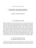
1. Actual size photographs of cores of different
voidages masked to give a standard area of
125 mm x 80 mm in each case
1
2
Foreword
This Part of this standard, prepared under the direction
of the Cement, Gypsum, Aggregates and Quarry Products
Standards Committee, is a revision of clause 3 of
BS 1881 : Part 4 : 1970. Together with Parts 115, 116, 117,
118 and 119, this Part of BS 1881 supersedes BS 1881 :
Part 4 : 1970, which is withdrawn.
This Part includes methods of sampling, drilling,
preparation of specimens and testing of cores from
concrete. The results of the test are given as the measured
core strength or the estimated in-situ cube strength which
are without allowance for the effect of curing history,
or age, or degree of compaction.
The relationship between core and cube strengths is
complex and will vary with particular conditions.
Planning of core testing and the interpretation of results
should be based on information and advice from the
specialist literature, e.g. BS 8110, BS 6089 and The
Concrete Society Technical Report No. 11.
The photographs in figure 1 are reproduced by permission
of The Concrete Society from Technical Report No. 11.
No estimate of repeatability or reproducibility is given in
this Part of this British Standard. Reference should be
made to BS 5497 : Part 1 for further information on
the determination of repeatability and reproducibility.
Compliance with a British Standard does not of itself
confer immunity from legal obligations.
I
BS 1881 : Part 120 : 1983
British Standard
Testing concrete
Part 120. Method for determination of the compressive strength of concrete cores
1. Scope
The usable length of core shall be such that the length/
diameter ratio for strength testing shall be between 1 and 2.
This Part of this British Standard describes a method for
taking cores from concrete and preparing them for testing
and for the method for determining their compressive
strength.
NOTE 2. The preferred length/diameter ratio is between 1 and 1.2.
If the whole length of a core is to be tested in compression,
the diameter shall be chosen in the specified ratio to the
depth of member from which the core is taken.
NOTE 1. Before deciding to drill cores for compressive testing,
it is essential that full consideration be given to the necessity for
the test, its aims and the value of the results which will be
obtained. Specialist literature, e.g. BS 8110, BS 6089, or the
Concrete Society Technical Report No. 11 should be consulted
for advice on the number of cores necessary, on the need for
trimming and for the assessment of results. It is recommended
that before coring full agreement should be reached by all parties
on the need for core testing and on how the results should be
interpreted.
NOTE 3. For the static modulus tests (see BS 1881 : Part 121) the
length/diameter ratio shall be at least 2 with a maximum of 5.
4.2 Drilling. Unless specifically required otherwise,
cores shall be drilled perpendicular to the surface using a
diamond core drilling bit and in such a manner as not to
damage the cores. The equipment shall comply with the
dimensional requirements of BS 4019 : Part 2. The drill
shall be kept rigidly positioned during coring, otherwise
ridged or curved cores may be obtained. Drilling through
reinforcement shall be avoided wherever possible.
NOTE 2. The titles of the publications referred to in this standard
are listed on the inside back cover.
2. Definitions
4.3 Identification. Immediately after cutting mark each
For the purposes of this Part of this standard the
definitions given in BS 5328 apply.
core clearly and indelibly, indicating its location and
orientation within the member. Record the direction of
drilling of each core relative to the direction of casting.
3. Apparatus
Mark the core to indicate distances in millimetres from
the drilling surfaces so that the location in the element
from which the test core came can be confirmed when
the ends have been trimmed.
3.1 Grinding equipment (required if end preparation is by
grinding, see 5.2). Grinding equipment capable of producing
a surface to the tolerances specified in 4.8.
4.4 Examination
3.2 Steel collar. A steel collar with a machined edge suitable for use when capping in accordance with 5.3 method
(a).
4.4.1 Compaction. Examine each specimen for
compaction, for the presence of voids, for honeycombing
and for cracks.
3.3 Glass capping plate (required if end capping in
accordance with method (a) of 5.3). A glass plate at least
8 mm thick with surfaces complying with the tolerances
specified in 4.8.
Note the position at which any honeycombing begins.
Describe the compaction of the concrete by comparing
the core surface with figures 1 (a) to 1 (e) by measuring
excess voidage which is that amount by which the actual
voidage exceeds the voidage of a well made cube of the
same concrete.
3.4 Steel plate (required if end capping in accordance with
method (b) of 5.3). A horizontal steel plate with an upper
surface having a flatness tolerance as defined in BS 308 of
0.03 mm wide, a surface texture not exceeding 3.2 pm Ra
when determined in accordance with BS 1134 and a
Rockwell (Scale B) Hardness Value* of at least 95 when
tested in accordance with BS 891 : Part 1.
Where the description needs to be amplified, this shall
be done by reference to the following terms.
(a) Small void. A void measuring not less than 0.5 mm
and not more than 3 mm across in any direction.
3.5 Compression testing machine complying with
(b) Medium void. A void having a dimension greater
than 3 mm but not greater than 6 mm.
BS 1881 : Part 115 and related to the size of specimens
and their expected failure load.
(c) Large void. A void having a dimension greater
than 6 mm.
4. Test specimens
(d) Honeycombing. Interconnected voids arising
from, for example, inadequate compaction or lack
of mortar.
4.1 Size of cores. Test specimens shall be 100 mm or
150 mm diameter; the preferred diameter size is 150 mm.
The ratio of diameter to the maximum aggregate size
shall be not less than 3.
In order to avoid extremes of subjective bias, two observers
shall compare the surface voids of a given core with those
shown in figure 1, taking care to ensure that the voids
NOTE 1. Concrete cube testing machines are not normally suitable
for testing cores of smaller diameter in compression.
*Indentations on the face resulting from the hardness test are acceptable.
1
BS 1881 : Part 120 : 1983
When it is necessary to reduce the length of core to
that appropriate to a particular test, saw the core
perpendicular to its longitudinal axis. When the core is
to be tested in compression, prepare flat ends preferably
by grinding as in 5.2 or by capping as in 5.3 if
grinding is impractical.
are viewed in strong light angled so as to highlight them
with shadows (as in figure 1). The procedure for the
comparison is as follows:
(a) cut a 125 mm x 80 mm rectangular aperture in
a piece of thin card;
(b) place the card on the core with elastic bands;
5.2 End preparation by grinding. Before grinding,
store cores in water at 20 ± 2 ºC. Remove them for not
more than 1 h for grinding and measurement. Grind the
ends of the cores to the tolerances given in 4.8. After
grinding, return the cores to the water.
(c) assess the excess voidage of the area of core in view
by comparing it with figure 1 and record the
assessment;
(d) move the card to other areas and repeat the
assessment until the cylindrical face of the core has
been surveyed representatively;
NOTE. The need to trim the length will depend on the purpose
for which the core was taken.
(e) average the individual assessments and record the
result to the nearest multiple of 0.5 90.
Grind the ends of the specimen for testing in compression
to the tolerances given in 4.8. Grinding is the preferred
method of end preparation but if this is impractical,
cap the ends using either of the two methods specified
in 5.3.
NOTE 1. Where the relative frequencies of small and large voids
on the test core differ from those shown in figure 1, estimation
of the excess voidage may be facilitated by remembering that a
void of a given diameter (or linear dimension) is equal in volume
to eight voids having only half that diameter (or linear dimension).
5.3 End preparation by capping. Before capping by method
(a), store cores in water at 20 ±2 º C. Before capping by
method (b), store cores in a dry condition. Caps shall be
made as thin as possible and shall not exceed 10 mm
thickness at any point.
NOTE 2. Where a photographic record of the air-dry core is
required, the centre of the photograph should include that
125 mm X 80 mm area having an estimated excess voidage
nearest to the average for the whole core. The lighting should
also be such that a photograph comparable in quality to figure 1
is obtained, and the photograph should be reproduced to actual size.
Before the.upper surface is capped the surface shall first
be roughened by hacking or wire brushing. The method
given in (a) is suitable for specimens which have been
soaked in water and the method given in (b) is suitable
for dry specimens.
4.4.2 Description of aggregate. When required, examine
pieces of coarse aggregate for general type and particle
shape according to BS 812. Estimate the maximum size
to the nearest appropriate size specified in BS 882.
4.4.3 Distribution of materials. Examine each core for
(a) The capping material consists of a mortar composed
of three parts by mass of high alumina cement complying with BS 915 to one part by mass of fine sand
(most of which passes a 300 µm BS 410 woven wire
sieve). Place the soaked specimen on a horizontal
plate, and rigidly clamp a steel collar of correct
diameter and having a machined upper edge to the
end of the specimen to be capped, in such a way that
the upper edge is horizontal and just extends above
the highest part of the concrete surface. Fill the capping
material into the collar until it is in the form of a
convex surface above the edge of the collar. Press down
the glass capping plate, coated with a thin film of
mould oil, on to the capping material with a rotary
motion until it makes complete contact with the
edge of the collar. Immediately place the specimen
with collar and plate in moist air of at least 90 % r.h.
and at a temperature of 20 ± 5 ºC, and remove the
plate and collar when the mortar is hard enough.
(b) The capping material consists of a mixture
composed of equal parts by weight of sulphur and
fine siliceous sand (most of which passes a 300 µm
BS 410 woven wire sieve and is retained on a 150 µm
BS 410 woven wire sieve) together with a small
proportron (1 % to 2 %) of carbon black. Alternatively,
use a mixture* of sulphur and pulverized-fuel ash in
suitable proportions to provide a higher strength than
evidence of segregation of the individual materials by
visually comparing the approximate coarse aggregate/
mortar ratio at different planes in the core.
4.5 Measurement of dimensions. Measure the diameter
and the length before and after end preparation (see 5.2)
in accordance with BS 1881 : Part 114.
4.6 Measurement of mass and density. Weigh each
specimen and determine the density as received or
saturated, in accordance with BS 1881 : Part 114.
4.7 Measurement of reinforcement. Measure the size and,
if possible, spacing of any reinforcing bars. Determine the
position of any reinforcement by measuring from the
centre of the exposed bars to the top of the core as
received and after end preparation (see 5.2).
4.8 Tolerances. The tolerances in accordance with BS 308 :
Part 3 of the prepared specimen shall be as follows.
(a) Flatness. The flatness tolerance for the prepared
end surfaces shall be 0.08 mm wide.
(b) Squareness. The squareness tolerance (squareness 3
of BS 308 : Part 3) for the end prepared first with
respect to the axis of the specimen as datum axis shall
be 2.0 mm wide.
(c) Parallelism. The parallelism tolerance (parallelism 4
of BS 308 : Part 3) for the prepared top surface with
respect to the bottom surface of the specimen as
datum face shall be 2.0 mm wide.
that of the concrete. Heat the mixture to a temperature
of approximately 130 ºC to 150 ºC and then allow it
to cool slightly while being stirred continuously. Pour
(d) Cylindricity. The cylindricity tolerance for the
core shall be 3 % of the core diameter.
the mixture onto a level machined steel plate that has
been slightly warmed and thinly coated with paraffin.
Place the specimen into this layer with its axis vertical
using a guide. After a few seconds, cut away the surplus
material around the specimen with a sharp knife and
lift the specimen off the plate. The cap shall not flow or
5. Preparation of cores
5.1 General. Cores which do not comply with the
requirement for cylindricity in 4.8 or that are badly
honeycombed should not be tested.
‘A granular mixture ready for use is available end for information on its supply apply to Enquiry Section, BSI, Linford Wood,
Milton Keynes MK14 6LE. enclosing a stamped addressed envelope for reply.
2
BS 1881 : Part 120 : 1983
(a) Excess voidage = 0
(b) Excess voidage = 0.5 %
(d0 Excess voldage = 3 0 %
9c0 Excess voidage = 1.5 %
Figure 1. Actual-size photographs of cores of different voidages masked to give
a standard area of 125 mm x 80 mm in each case
3
BS 1881 : Part 120 : 1983
slow down; at this stage operate the controls rapidly and
smoothly to maintain as far as possible the specified
loading rate. Record the maximum load. Normal failures
are reasonably symmetrical. Note any unusual failures
and the appearance of the concrete.
7. Calculation and expression of results
7.1 Calculation and expression of results. Calculate the
compressive strength of each core by dividing the
maximum load by the cross-sectional area, calculated
from the average diameter. Express the results to the
nearest 0.5 N/mm2.
NOTE. The presence of reinforcement in cores cut from
reinforced concrete may affect the result.
7.2 Estimated in-situ cube strength
7.2.1 For cores free of reinforcement. Calculate the
estimated in-situ cube strength to the nearest 0.5 N/mm2
from the equation
estimated in-situ
cube strength
D
1.5+
measured compressive
strength of core
where
D is 2.5 for coresdrilled horizontally (for precast units
perpendicular to height when cast); or 2.3 for cores
drilled vertically (for precast units parallel to height
when cast);
A is the length (after end preparation) /diameter ratio.
NOTE. It should be noted that in-situ strengths estimated from
the above formula cannot be equated to standard cube strengths.
7.2.2 For cores with reinforcement perpendicular to the
core axes. Calculate the estimated in-situ cube strength by
(e) Excess voidage = 13.0 %
multiplying the strength obtained from the formula
in 7.2.1 by the following factors:
Figure 1. (concluded)
(a) for cores containing a single bar:
fracture before the concrete fails when the specimen is
tested.
1.0+ 1.5
5.4 Storage. After end preparation by grinding or
capping, immerse the specimen in water at 20 ± 2 ºC
for at least 1 h and until it is in a saturated condition
for testing. Do not test cores from high strength concrete
capped with high alumina cement mortar until the caps
reach a higher strength than that expected for the
concrete.
(b) for specimens containing two bars no further apart
than the diameter of the larger bar, only the bar
corresponding to the higher value
need be
considered. If the bars are further apart, their combined
effect should be assessed by using the factor:
1.0+ 1.5
6. Procedure
6.1 General. Test the core in compressron not less than
2 days after end preparation and immersing in water.
Cores with cracked or loose caps shall not be tested.
Test the core immediately on removal from the water
and whilst it is still wet.
where
is the diameter of the reinforcement;
is the diameter of specimen;
d is the distance of axis of bar from nearer end
of specimen;
6.2 Placing the core in the testing machine. Wipe the
bearing surfaces of the testing machine and of any
auxiliary platens clean and remove any water, loose sand
or other material from the ends of the core. Centre the
core carefully on the lower platen of the machine.
Wherever possible use a jig to align the specimen, Do not
use any packing other than auxiliary steel platens
between the ends of the core and the platens of the
testing machine.
is the length of the specimen after end
preparation by grinding or capping.
8. Test report
8.1 General. The report shall affirm that the specimens
were taken, prepared and tested in accordance with this
Part of this standard.
6.3 Loading. Without shock apply and increase the load
continuously at a constant rate within the range of
0.2 N/(mm2.s) to 0.4 N/(mm2.s) until no greater load can
be sustained. On manually controlled machines as failure
is approached the load-indicator pointer will begin to
4
BS 1881 : Part 120 : 1983
8.2 Information to be provided by the producer of the
test specimens for inclusion in the test report
(d) average diameter;
(e) maximum and minimum lengths, as-received;
8.2.1 Mandatory information.
The following information
shall be provided by the producer of the test specimens
for inclusion in the test report:
(f) density of the specimen (as-received or saturated
and the method of determining the volume);
(g) length after preparation, and location in relation
to the length received;
(a) identification of the core (see 4.3);
(b) date of drilling;
(h) method of end preparation;
(c) direction of drilling relative to direction of casting,
e.g. vertically, horizontally or diagonally;
(i) compaction of concrete, distribution of materials,
classif ication of voids and presence of cracks;
(d) name of person taking cores;
(j) date of test;
(e) conditions of storage.
(k) age of specimen, when known, at date of test;
(f) required age of concrete at time of testing, if known.
(I) length of time specimen was stored in water before
strength testing;
8.2.2 Optional information. If requested the following
information shall be provided by the producer of the test
specimens for inclusion in the test report:
(m) maximum load of failure;
(n) measured compressive strength and estimated
in-situ cube strength;
(a) name of project;
(b) component or part of project;
(0) appearance of concrete and type of fracture;
(c) specified concrete strength;
(p) size, position and spacing of any reinforcement;
(d) concrete mix details;
(q) certificate that the test has been carried out in
accordance with this Part of this standard;
(e) admixtures used.
8.3 Information to be provided by the test laboratory for
inclusion in the test report
8.3.1 Mandatory information. The following information
shall be provided by the test laboratory for inclusion in
the test report:
(r) other remarks.
8.3.2 Optional information. If requested the following
information shall be provided by the test laboratory for
inclusion in the test report:
(a) identification of the specimen;
(a) copy of the photograph, or photographs, of the
core as-received;
(b) condition of specimen when received (include poor
compaction, honeycombing or bad dimensions);
(b) description of aggregate, including maximum size,
group classification, particle shape;
(c) date of receipt of the specimen;
(c) other remarks,
Publications referred to
BS 308
BS 410
BS 812
BS 882
BS 891
BS 915
BS 1134
BS 1881
BS 4019
BS 5328
BS 5497
BS 6089
BS 8110
Engineering drawing practice
Part 3 Geometrical tolerancing
Specification for test sieves
Methods for sampling and testing of mineral aggregates, sands and fillers
Coarse and fine aggregates from natural sources
Method for Rockwell hardness test
Part 1 Testing of metals
High alumina cement
Method for the assessment of surface texture
Testing concrete
Part 114 Method for determination of density of hardened concrete
Part 115 Specification for compression testing machine for concrete
Part 121 Method for determination of static modulus of elasticity in compression
Core drilling equipment
Part 2 Concrete drilling equipment
Methods for specifying concrete, including ready-mixed concrete
Precision of test methods
Part 1 Guide for the determination of repeatability and reproducibility for a standard test method
Guide to the assessment of concrete strength in existing structures
Structural use of concrete
Part 1 Code of oractice for design and construction
*Concrete Society Technical
Report No. 11
*The Concrete Society, Concrete core testing for strength. London, May 1976. (including addendum 19871. Technical Report No. 11.
Obtainable from the Concrete Society, Devon House, 12 - 15 Dartmouth Street, London SW1H 9BL.
5
BS 1881 : Part 120 : 1983
This Britrsh Standard, having been prepared under the direction of
the Cement, Gypsum, Aggregates and Quarry Products Standards
Committee, was published under the authority of the Standards
Board and comes into effect on 31 January 1983.
standard. of necessary details such as symbols and size, type or grade
designations. Enquiries should be addressed to the Publications
Manager, BSI, Linford Wood, Milton Keynes MK14 6LE. The number
for telephone enquiries is 0906 220022 and for telex 625777.
©British Standards institution, 1983
Contract requirements. A British Standard does not purport to include
ISBN 0 580 12957 8
all the necessary provisions of a contract. Users of British Standards
are responsible for their correct application.
Revision of British Standards. British Standards are revised, when
Brltlsh Btandards Institution. Incorporated by Royal Charter, BSI is the
independent national body for the preparation of British Standards. It
is the UK member of the International Organizotion for
Standardisation and UK sponsor of the British National Committee of
the International Electrotechnical Commission.
In addition to the preparation and promulgation of standards, BSI
offers specialist services including the provision of information
through the BSI Library and Standardline Database; Technical Help to
Exporters, and other services. Advice can be obtained from the
Enquiry Section, BSI, Milton Keynes MK14 6LE, telephone
0906 221166, telex 625777.
Copyright. Users of British Standards are reminded that copyright
subsists in all BSI publications. No part of this publication may be
reproduced in any form without the prior permission in writing of BSI.
This does not preclude the free use. in the course of implementing the
necessary, by the iissue either of amendments or of revised editions.
It is important that users of British Standards should
ascertain that
they are in possession of the latest amendments or editions.
Automatic updating service. BSI provides an economic, individual
and automatic standards updating service called PLUG. Details are
available from BSI Enquiry Section at Milton Keynes, telephone
0908 221166, telex 825777.
Information on all BSI publications is in the BSI Catalogue,
supplemented each month by BSI News which is available to
subscribing members of BSI and gives details of new publications,
revisions, amendments and withdrawn standards. Any person who,
when making use of a British Standard, encounters an inaccuracy or
ambiguity, is requested to notify BSI without delay in order that the
matter may be investigated and appropriate action taken.
Cooperating organizations
The Cement, Gypsum, Aggregates and Quarry Products Standards
Committee, under whose direction this British Standard was
prepared, consists of representatives from the following:
Association of Consulting Engineers
Association of County Councils
Association of District Councils
Association of Metropolitan Authorities
Autoclaved Aerated Concrete Products Association
*British Precast Concrete Federation Ltd.
‘British Quarrying and Slag Federation
British Railways Board
*British Ready Mixed Concrete Association
British Steel Industry
Cement Admixtures Association
‘Cement and Concrete Association
*Cement Makers’ Federation
Chemical Industries Association
*Concrete Society Limited
*County Surveyors’ Society
*Department of the Environment (Building Research
Establishment)
*Department of the Environment (PSA)
*Department of the Environment (Transport and Road Research
Laboratory)
*Department of Transport
‘Federatton of Civil Engineering Contractors
Gypsum Products Development Association
Institute of Quarrying
‘Institution of Civil Engineers
‘Institution of Highway Engineers
*Institution of Municipal Engineers
Institution of Public Health Engineers
‘Institution of Structural Engineers
‘Institution of Water Engineers and Scientists
l national Federation of Building Trades Employers
Natural Environment Research Council (Institute of Geological
Science)
‘Royal Institute of British Architects
‘Royal Institution of Chartered Surveyors
Sand and Ballast Hauliers and Allied Trades Alliance
*Sand and Gravel Association Limited
‘Society of Chemical Industry
Stone Federation
The organisations marked with an asterisk in the above list,
together with the following, were directly represented on the
Technical Committee entrusted with the preparation of this
British Standard:
British Civil Engineering Test Equipment Manufacturers’
Association
Electricity Supply Industry in England and Wales
Greater London Council
Institute of Concrete Technology
Coopted member
Amendments issued since publication
Amd. No.
Date of issue
Text affected
6109
July 1989
Indicated by a line in the margin
British Standards Institution . 2 Park Street London W1A 2BS Telephone 071-629 9000 . Telex 266933
9710-0.1k-DP
CAB/4