Astm d 3350 21
Bạn đang xem bản rút gọn của tài liệu. Xem và tải ngay bản đầy đủ của tài liệu tại đây (247.33 KB, 8 trang )
This international standard was developed in accordance with internationally recognized principles on standardization established in the Decision on Principles for the
Development of International Standards, Guides and Recommendations issued by the World Trade Organization Technical Barriers to Trade (TBT) Committee.
Designation: D3350 − 21
Standard Specification for
Polyethylene Plastics Pipe and Fittings Materials1
This standard is issued under the fixed designation D3350; the number immediately following the designation indicates the year of
original adoption or, in the case of revision, the year of last revision. A number in parentheses indicates the year of last reapproval. A
superscript epsilon (´) indicates an editorial change since the last revision or reapproval.
responsibility of the user of this standard to establish appropriate safety, health, and environmental practices and determine the applicability of regulatory limitations prior to use.
1. Scope*
1.1 This specification covers the identification of polyethylene plastic pipe and fittings materials in accordance with a
cell classification system. It is not the function of this specification to provide specific engineering data for design purposes,
to specify manufacturing tolerances, or to determine suitability
for use for a specific application.
1.1.1 Some plastic pipe and fitting PE compounds classified
by this standard are sold as a base material and then combined
with other material(s) (for example, color or additive concentrate) by the pipe or fitting manufacturer into a final classified
compound either prior to or during production of the final
article. This standard, excluding the requirements of Table 1,
properties 5 and 6, and 6.1.1, can be used for property
verification of the incoming base material(s) in accordance
with 8.1.
1.1.2 In the case of PE compounds sold as the compound
classified by the standard, see 8.1 regarding property verification of the incoming classified compound.
1.1.3 Compounds with a cell classification value other than
‘0’ for the Hydrostatic Strength Classification (property 6) rely
on a defined formulation. The composition of the defined
formulation can be obtained from the owner of the formulation.
NOTE 4—There is no known ISO equivalent to this standard.
1.5 For information regarding molding and extrusion materials see Specification D4976. For information regarding wire
and cable materials see Specification D1248.
1.6 This international standard was developed in accordance with internationally recognized principles on standardization established in the Decision on Principles for the
Development of International Standards, Guides and Recommendations issued by the World Trade Organization Technical
Barriers to Trade (TBT) Committee.
2. Referenced Documents
2.1 ASTM Standards:2
D618 Practice for Conditioning Plastics for Testing
D638 Test Method for Tensile Properties of Plastics
D746 Test Method for Brittleness Temperature of Plastics
and Elastomers by Impact
D790 Test Methods for Flexural Properties of Unreinforced
and Reinforced Plastics and Electrical Insulating Materials
D792 Test Methods for Density and Specific Gravity (Relative Density) of Plastics by Displacement
D883 Terminology Relating to Plastics
D1238 Test Method for Melt Flow Rates of Thermoplastics
by Extrusion Plastometer
D1248 Specification for Polyethylene Plastics Extrusion
Materials for Wire and Cable
D1505 Test Method for Density of Plastics by the DensityGradient Technique
D1603 Test Method for Carbon Black Content in Olefin
Plastics
D1693 Test Method for Environmental Stress-Cracking of
Ethylene Plastics
D1898 Practice for Sampling of Plastics (Withdrawn 1998)3
NOTE 1—Deviations from the defined formulation may affect the
Hydrostatic Strength Classification.
1.2 Polyethylene plastic materials, being thermoplastic, are
reprocessable and recyclable (Note 3). This specification allows for the use of those polyethylene materials, provided that
all specific requirements of this specification are met.
NOTE 2—The notes in this specification are for information only and
shall not be considered part of this specification.
NOTE 3—See Guide D5033 for information and definitions related to
recycled plastics.
1.3 The values stated in SI units are to be regarded as
standard.
1.4 This standard does not purport to address all of the
safety concerns, if any, associated with its use. It is the
2
For referenced ASTM standards, visit the ASTM website, www.astm.org, or
contact ASTM Customer Service at For Annual Book of ASTM
Standards volume information, refer to the standard’s Document Summary page on
the ASTM website.
3
The last approved version of this historical standard is referenced on
www.astm.org.
1
This specification is under the jurisdiction of ASTM Committee D20 on
Plastics and is the direct responsibility of Subcommittee D20.15 on Thermoplastic
Materials.
Current edition approved July 1, 2021. Published July 2021. Originally approved
in 1974. Last previous edition approved in 2014 as D3350 – 14. DOI: 10.1520/
D3350-21.
*A Summary of Changes section appears at the end of this standard
Copyright © ASTM International, 100 Barr Harbor Drive, PO Box C700, West Conshohocken, PA 19428-2959. United States
1
D3350 − 21
TABLE 1 Primary PropertiesA —Cell Classification Limits
Test
Method
0
1
2
3
4
5
6
7
1. Density, g/cm3
D1505
Unspecified
0.925 or
lower
>0.9250.940
>0.9400.947
>0.9470.955
>0.955
...
Specify
Value
2. Melt index
D1238
Unspecified
>1.0
1.0 to
0.4
<0.4 to
0.15
<0.15B
C
3. Flexural
modulus, MPa (psi)
D790
Unspecified
<138
(<20 000)
552<758
(80 000 to
110 000)
758<1103
(110 000 to
<160 000)
>1103
(>160 000)
Specify
Value
4. Tensile strength
at yield, MPa (psi)
D638
Unspecified
<15
(<2200)
15-<18
(2200<2600)
18-<21
(2600<3000)
21-<24
(3000<3500)
24-<28
(3500<4000)
>28
(>4000)
Specify
Value
D1693
Unspecified
A
B
C
C
...
...
...
Specify
Value
Unspecified
48
50
24
50
192
20
600
20
Unspecified
...
...
...
10
30
100
500
Specify
Value
5.52
(800)
...
6.89
(1000)
...
8.62
(1250)
...
11.03
(1600)
...
...
...
8
(1160)
10
(1450)
Property
5. Slow Crack
Growth Resistance
I. ESCR
a. Test condition
(100% Igepal.)D
b. Test duration, h
c. Failure, max, %
II. PENT (hours)
Molded plaque,
80°C, 2.4 MPa
Notch depth,
F1473, Table 1
6. Hydrostatic Strength
Classification
I. Hydrostatic design
basis, MPa (psi), (23°C)
II. Minimum required
strength, MPa (psi), (20°C)
138276<276
<552
(20 000 to (40 000 to
<40 000)
80 000)
8
Specify
Value
F1473
Unspecified
D2837
NPRE
ISO 12162
...
A
Compliance with physical properties in accordance with Section 8 is required including requirements for cell classification, color, and ultraviolet (UV) stabilizer, thermal
stability, brittleness temperature, density, tensile strength at yield, and elongation at break.
B
Refer to 10.1.4.1.
C
Refer to 10.1.4.2.
D
There are environmental concerns regarding the disposal of Nonylphenoxy poly(ethyleneoxy) ethanol (CAS 68412-54-4) for example, Igepal CO-630. Users are advised
to consult their supplier or local environmental office and follow the guidelines provided for the proper disposal of this chemical.
E
NPR = Not Pressure Rated.
F2263 Test Method for Evaluating the Oxidative Resistance
of Polyethylene (PE) Pipe to Chlorinated Water
2.2 ISO Standard:
ISO 12162 Thermoplastic Materials for Pipes and Fittings
for
Pressure Applications—Classification
and
Designation—Overall Service (Design) Coefficient
D2837 Test Method for Obtaining Hydrostatic Design Basis
for Thermoplastic Pipe Materials or Pressure Design Basis
for Thermoplastic Pipe Products
D2839 Practice for Use of a Melt Index Strand for Determining Density of Polyethylene
D3035 Specification for Polyethylene (PE) Plastic Pipe (DRPR) Based on Controlled Outside Diameter
D3892 Practice for Packaging/Packing of Plastics
D4218 Test Method for Determination of Carbon Black
Content in Polyethylene Compounds by the MuffleFurnace Technique
D4703 Practice for Compression Molding Thermoplastic
Materials into Test Specimens, Plaques, or Sheets
D4883 Test Method for Density of Polyethylene by the
Ultrasound Technique
D4976 Specification for Polyethylene Plastics Molding and
Extrusion Materials
D5033 Guide for Development of ASTM Standards Relating
to Recycling and Use of Recycled Plastics (Withdrawn
2007)3
F1473 Test Method for Notch Tensile Test to Measure the
Resistance to Slow Crack Growth of Polyethylene Pipes
and Resins
3. Terminology
3.1 Definitions:
3.1.1 Terms as described in Terminology D883 shall apply
in this specification.
3.1.2 polyethylene plastics, n—as defined by this
specification, plastics or resins prepared by the polymerization
of no less than 85 % ethylene and no less than 95 % of total
olefins with additional compounding ingredients.
3.2 Definitions of Terms Specific to This Standard:
3.2.1 base materials, n—PE material without non-black or
black pigment, supplied to industry, that is either a PE
compound classified by this Standard or a component of a PE
compound classified by this standard.
3.2.2 PE compounds, n—has the same meaning as PE
plastics materials, compounds, and plastics.
2
D3350 − 21
characterization, and specification of material properties. The
information from the format is to be used alone or in
combination.
3.3 Historical usage and user group conventions have resulted in inconsistent terminology used to categorize and
describe polyethylene resins and compounds. The following
terminology is in use in ASTM specifications pertaining to
polyethylene:
3.3.1 Specification D1248:
3.3.1.1 Type (0, I, II, III, IV) = density ranges (same,
respectively, as Class in Specification D4976).
3.3.1.2 Class (A, B, C, D) = composition and use.
3.3.1.3 Category (1, 2, 3, 4, 5) = melt index ranges (same as
Grade in Specification D4976).
3.3.1.4 Grade (E, J, D, or W followed by one or two digits)
= specific requirements from tables.
3.3.2 Specification D3350:
3.3.2.1 Type (I, II, III) = density ranges (same as Types I, II,
and III in Specification D1248 and Classes 1, 2, and 3 in
Specification D4976).
3.3.2.2 Class = a line callout system consisting of “PE”
followed by six cell numbers from Table 1 plus a letter (A, B,
C, D, E) denoting color and UV stabilizer.
3.3.2.3 Grade = simplified line callout system using “PE”
followed by density and slow crack growth cell numbers from
Table 1.
3.3.3 Specification D4976:
3.3.3.1 Group (1, 2) = branched or linear polyethylene.
3.3.3.2 Class (0, 1, 2, 3, 4) = density ranges (same,
respectively, as Type in Specification D1248).
3.3.3.3 Grade (1, 2, 3, 4, 5) = melt index ranges (same as
Category in Specification D1248).
NOTE 7—This type format, however, is subject to possible misapplication since unobtainable property combinations can be selected if the user
is not familiar with commercially available materials. The manufacturer
should be consulted. Additionally, the appropriate ASTM standard specification should be reviewed to assure materials utilized will meet all the
material and piping requirements as specified in the standard.
4.3 Grade—A code for polyethylene pipe and fittings materials that consists of the two letter abbreviation for polyethylene (PE) followed by two numbers that designate the density
cell (Property 1) and the slow crack growth resistance cell
(Property 5), as defined by either Test Method F1473 or Test
Method D1693, of the thermoplastic, as specified in Table 1.
For the requirements of Property 5 (slow crack growth
resistance), consult the materials section of the appropriate
ASTM standard specification for the end-use application.
NOTE 8—Grade designations were adapted from Specification
D1248 – 84 prior to the removal of pipe material from D1248 - 84.
Former Specification D1248 – 84 grades for PE pipe materials were P14,
P23, P24, P33, and P34. Equivalent Specification D3350 grade designations for these materials are PE11, PE20, PE23, PE30, and PE33,
respectively.
5. Materials and Manufacture
5.1 The molding and extrusion material shall be polyethylene plastic in the form of powder, granules, or pellets.
5.2 The molding and extrusion materials shall be as uniform
in composition and size and as free of contamination as is
achieved by good manufacturing practice. If necessary, the
level of contamination may be agreed upon between the
manufacturer and the purchaser.
4. Classification
5.3 When specified, the color and translucence of molded or
extruded pieces formed, under the conditions specified by the
manufacturer of the materials, shall be comparable within
commercial match tolerances to the color and translucence of
standard samples supplied in advance by the manufacturer of
the material.
4.1 Polyethylene plastic pipe and fittings compounds are
classified in accordance with density, melt index, flexural
modulus, tensile strength at yield, slow crack growth
resistance, and hydrostatic strength classification in Table 1.
NOTE 5—It has been a long-standing practice to use the following terms
in describing polyethylene plastics:
6. Physical Properties
Type I (0.910 to 0.925) = Low Density
Type II (0.926 to 0.940) = Medium Density
Type III (0.941 to 0.965) = High Density
6.1 Cell Classification—Test values for specimens of the PE
material prepared as specified in Section 9 and tested in
accordance with Section 10 shall conform to the requirements
given in Table 1. A typical property value for a PE material is
to be the average value from testing numerous lots or batches
and determines the cell number. When, due to manufacturing
tolerances and testing bias, individual lot or batch values fall
into the adjoining cell, the individual value shall not be
considered acceptable unless the user, or both the user and the
producer, determine that the individual lot or batch is suitable
for its intended purpose.
6.1.1 For PE compounds with a code letter designation of A,
all properties shall be determined, for classification purposes,
on the non-pigmented (natural) material. For PE compounds
with any other code letter designation, all properties other than
density, in accordance with 6.5, shall, for classification
purposes, be determined on the PE compound represented by
that code letter (for example, black [C], colored with UV
stabilizer [E], etc.)
NOTE 6—The manner in which materials are identified in the cell
classification is illustrated for Class PE233424B as follows (refer also to
Table 1 and 6.2):
Class
2 3 3 4 2 4 B
Density (0.926–0.940 g/cm3)
Melt Index (<0.4–0.15)
Flexural Modulus (276–<552 MPa)
Tensile Strength at yield
(21–<24 MPa (3000–<3500 psi))
Slow Crack Growth Resistance
I. ESCR D1693
Condition B, 24 h, 50% max failure
II. PENT F1473
Average 1 h failure
Hydrostatic design basis at 23°C
(11.03 MPa (1600 psi))
Color and UV stabilizer (colored)
4.2 Materials used in polyethylene plastic pipe and fittings
shall use a cell-type format for the identification, close
3
D3350 − 21
TABLE 2 Minimum Log Average Test Times for Oxidative
Resistance Classification
6.2 Color and Ultraviolet (UV) Stabilizer—The color and
UV stabilization shall be indicated at the end of the cell
classification by means of a letter designation in accordance
with the following code:
Code Letter
A
B
C
D
E
Categorization
Color and UV Stabilizer
Natural
Colored
Black with a carbon black in
the range as noted in 6.2.1 and 6.2.2
Natural with UV stabilizer
Colored with UV stabilizer
CC0
CC1
CC2
CC3
6.2.1 For PE compounds with a hydrostatic strength classification cell class 0 (not pressure-rated), the carbon black
content shall be in the range of 2.0 % to 4.0 %.
6.2.2 For PE compounds with a hydrostatic strength classification other than cell class 0, the carbon black content shall
be in the range of 2.0 % to 3.0 %.
90°C (194°F) Test Temperature
Test Stress 2.48
Test Stress 2.76
Test Stress 3.10
MPa (360 psi)
MPa (400 psi)
MPa (450 psi)
Time (h)
Time (h)
Time (h)
Unspecified
Unspecified
Unspecified
2700
1900
1200
7400
5100
3400
16 200
11 100
7400
class specified in 3.3.2.2, the user shall specify an oxidative
resistance requirement by appending the category designation
requirement (Table 2) to the line call out.
6.8.2 The oxidative resistance time used to classify the PE
compound shall be determined in accordance with 10.1.11 and
be classified in accordance with Table 2.
6.3 Thermal Stability—The PE material shall contain sufficient antioxidant so that the minimum induction temperature
shall be 220°C when tested in accordance with 10.1.9.
7. Sampling
7.1 A batch or lot shall be considered as a unit of manufacture and shall consist of one production run or as a blend of two
or more production runs of material.
6.4 Brittleness Temperature—The brittleness temperature
shall not be warmer than −60°C when tested in accordance
with Test Method D746.
7.2 Unless otherwise agreed upon between the manufacturer
and the purchaser, the material shall be sampled in accordance
with the procedure described in Sections 9 through 12 of
Practice D1898. Adequate statistical sampling prior to packaging shall be considered an acceptable alternative.
6.5 Density—The density used to classify the material shall
be the density of the PE base material (non-pigmented PE)
determined in accordance with 10.1.3. When the average
density of any lot or shipment falls within 60.002 g/cm3 of the
nominal value, it shall be considered as conforming to the
nominal value and to all classifications based on the nominal
value.
6.5.1 For black compounds, containing carbon black, determine the density, Dp, and calculate the resin density, Dr, as
follows:
NOTE 9—A sample taken from finished product may not necessarily
represent the original batch or lot.
8. Number of Tests
8.1 The requirements identified by the material designation
and otherwise specified in the purchase order shall be verified
by tests made in accordance with 11.1. For routine inspection,
only those tests necessary to identify the material to the
satisfaction of the purchaser shall be required. One sample
shall be sufficient for testing each batch or lot provided that the
average values for all of the tests made on that batch or lot
comply with the specified requirements.
Dr 5 Dp 2 0.0044C
where:
C = weight percent of carbon black.
6.5.2 For colored compounds, the nominal density of the
base material shall be provided by the manufacturer, on
request.
9. Specimen Preparation
6.6 Tensile Strength at Yield—The tensile strength at yield
used to classify the material shall be the tensile strength at yield
of the PE resin determined in accordance with 10.1.6. When
the average tensile strength at yield of any lot or shipment falls
within 63.45 MPa (6500 psi) of the nominal value, it shall be
considered as conforming to the nominal value and to all
classifications based on the nominal value.
9.1 Unless otherwise specified in Section 10, the test specimens shall be molded in accordance with Procedure C of
Annex A1 of Practice D4703.
6.7 Elongation at Break—As tested in accordance with
10.1.6, all pressure rated materials shall have a minimum
extension at break of 400 %.
10. Test Methods
9.2 When pipe or fitting test specimens are required, they
shall be extruded or molded in accordance with the specifications of the material manufacturer.
10.1 The properties enumerated in this specification shall be
determined in accordance with the following test methods:
10.1.1 Conditioning—Unless otherwise specified in the test
methods or in this specification, for those tests where conditioning is required, condition the molded test specimens in
accordance with Procedure A of Practice D618.
10.1.2 Test Conditions—Unless otherwise specified in the
test methods or in this specification, conduct tests at the
standard laboratory temperature of 23 6 2°C (73.4 6 3.6°F).
6.8 Oxidative Resistance Classification:
6.8.1 The Oxidative Resistance Classification is a classification of a PE compound’s resistance to the oxidative effects of
chlorinated potable water. The classification is only for PE
compounds intended for potable water pressure piping applications as noted in the materials requirement section of the
appropriate ASTM standard specification. In addition to the
4
D3350 − 21
mm/min (20 in./min for materials in the density range from
0.910 to 0.925 g/cm3) and 50 mm/min (2 in./min for all others).
Specimens shall conform to the dimensions given for Type IV
in Test Method D638 with a thickness of 1.9 6 0.2 mm
(0.075 6 0.008 in.). Specimen shall be either die cut or
machined.
10.1.7 Slow Crack Growth Resistance—One method shall
be used to classify this material property.
10.1.7.1 Slow Crack Growth Resistance—The material’s
resistance shall meet the minimum requirement shown for the
appropriate cell classification when tested in accordance with
Test Method D1693.
10.1.7.2 Slow Crack Growth Resistance—The average failure time from two test specimens shall meet the minimum
requirement shown for the appropriate cell classification when
tested in accordance with Test Method F1473. Test at least four
specimens in case of a dispute.
10.1.8 Hydrostatic Strength Classification—One method
shall be used to classify this material property.
10.1.8.1 Hydrostatic Design Basis—Determine the hydrostatic design basis in accordance with Test Method D2837, on
pipe extruded from three different lots of material. Subject
specimens from one lot for at least 10 000 h. Terminate the
tests on the two additional lots after 2000 h. The results from
each of the three lots shall be within the same or next higher
cell limits.
10.1.3 Density—Test Method D1505 or alternative methods
referenced in 2.1 (see D792, D2839, and D4883) providing
equivalent accuracy. Make duplicate determinations using two
separate portions of the same molding or from two moldings.
The molded specimen thickness portions shall be 1.9 6 0.2
mm (0.075 6 0.008 in.). Calculate the average value.
10.1.4 Melt Index—Test Method D1238, using Condition
190/2.16. Make duplicate determinations on the material in the
form of powder, granules, or pellets, and calculate the average;
no conditioning is required.
10.1.4.1 For materials having a melt index less than 0.15
(Cell 4), the manufacturer shall report a flow rate not greater
than 20 g/10 min and not less than 4.0 g/10 min when tested in
accordance with Test Method D1238, Condition 190/21.6.
10.1.4.2 Classify materials having a melt index less than
0.15 (Cell 4) as Cell 5 only if they have a flow rate not greater
than 4.0 g/10 min when tested in accordance with Test Method
D1238, Condition 190/21.6.
NOTE 10—For materials having a melt index less than 0.40 to 0.15 g/10
min (Cell 3), the manufacturer may report a flow rate value when tested
in accordance with Test Method D1238, Condition 190/21.6. For nonpressure applications, if agreed upon between the manufacturer and the
purchaser, the manufacturer may report only the melt index.
NOTE 11—Flow rate is the general term used for all results obtained
with Test Method D1238. Although the flow rate of polyethylene plastics
may be measured under any of the conditions listed for it under 7.2 of Test
Method D1238, only measurements made at Condition 190/2.16 may be
identified as “Melt Index.”
NOTE 12—For pressure application at elevated temperatures, the
hydrostatic design basis should be determined at that temperature in
accordance with Test Method D2837. The 100 000-h intercept should be
categorized in accordance with Table 1 of Test Method D2837.
10.1.5 Flexural Modulus—Test Methods D790, using
Method 1, Procedure B, and a 50-mm (2-in.) test span. Test five
specimens, each 3.2 by 12.7 mm (1⁄8 by 1⁄2 in.) flatwise at a
crosshead speed of 12.7 mm/min (0.5 in./min) and the average
value of the secant modulus calculated at 2 % strain in the
outer fibers.
10.1.5.1 The deflection of the test specimen corresponding
to 2 % strain (0.02 mm/mm or in./in.) is calculated as follows:
10.1.8.2 Minimum Required Strength—Determine the minimum required strength in accordance with ISO 12162.
10.1.9 Thermal Stability—Test specimens taken from pipe
or fittings made from the virgin material with a differential
scanning calorimeter (DSC).4 The directions of the instrument
manufacturer regarding calibration and operation shall be
followed except when in conflict with other parts of this
section.
D 5 rL2 /6d
where:
D = deflection of the center of the beam test specimen at 2 %
strain, in.,
r = strain in the outer fibers = 0.02 mm/mm (0.02 in./in.),
L = test span = 50 mm (2 in.), and
d = specimen depth = 3.2 mm (1⁄8 in.).
NOTE 13—This test requires accurate temperature and atmosphere
control on the DSC specimen compartment. The DSC manufacturers offer
choices in cell configuration and temperature control parameters that may
affect this required control. For example, in some power compensation
DSCs, use of the two-hole platinum specimen holder lids with a special
“flow-through” swing-away block cover is required. Therefore, the user
may wish to consult equipment-specific literature and with the equipment
manufacturer to optimize the operation of individual DSCs for this test.
10.1.5.2 The stress corresponding to 2 % strain is calculated
as follows:
10.1.9.1 Specimens—Press small pieces of the pipe into
films 0.127 6 0.013 mm (0.0050 6 0.0005 in.) thick. Cut at
least three disks 6.35 6 0.13 mm (0.250 6 0.005 in.) in
diameter from the film.
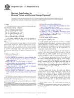
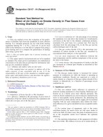
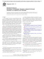
10.1.9.2 Procedure—Place the disk of film in a small
aluminum cup used in the DSC in a stretched condition, as
shown in Fig. 1(a). Place a small piece of indium (melting
point 156.6°C) or anisic acid (melting point 183.0°C) for a
temperature reference standard contained in a similar cup (see
Fig. 1(b)) in the reference position. Use an oxidized copper
S 5 3 PL/2 bd2
where:
S = stress in the outer fiber at 2 % strain,
P = load corresponding to 2 % strain, N (lbf),
L = test span = 50 mm (2 in.),
d = specimen depth = 3.2 mm (1⁄8 in.), and
b = specimen width = 12.7 mm (1⁄2 in.).
The secant modulus at 2 % strain is the ratio of stress to
strain or S/0.02.
10.1.6 Tensile Strength at Yield—The tensile strength at
yield and elongation at break shall be determined in accordance
with Test Method D638. The speed of testing shall be 500
4
5
Instruments are available from TA Instruments, Perkin-Elmer, and others.
D3350 − 21
FIG. 1 Mounting Film Specimen in Cup
10.1.10 Carbon Black Content—Test Method D1603 or Test
Method D4218 shall be used. Make duplicate determinations
from a sample of the material in the form of powder, granules,
or pellets.
10.1.11 Oxidative Resistance Test—Test specimens shall
consist of extruded 4-in. DR11 IPS pipe meeting the dimensional requirements of Specification D3035. All specimens
shall be from the same lot of pipe. Test a minimum of five (5)
specimens in accordance with Test Method F2263 at one of the
temperature and stress combinations of Table 2.
reference disk for black, filled, or dark brown test specimens
and an aluminum disk for natural or light pigmented polymers.
Place the specimen and reference standard cups in the instrument which is preset at approximately 150°C. The bottoms of
the cups shall be pressed and rubbed securely against the flat
surface so as to ensure that thermal contact is made. Allow 5
min for the cups to reach thermal equilibrium. Begin the
programmed heating at approximately 150°C at a heating rate
of 10.0°C/min in static air. Test at least three film specimens
from each sample and use the average value for the induction
temperature.
NOTE 15—If a selected temperature/stress condition results in premature failures, testing may be conducted at a lower stress as shown in Table
2.
NOTE 14—Since the indium standard may change with use, it should
not be used more than 30 times without confirming that no significant
change in melting point has occurred. This check can be made by
comparison with a fresh piece of indium.
10.1.11.1 Calculation—Calculate the log average test time
using all failures and non-failures. All specimens shall have
been tested at the same nominal test stress. Data from not less
than five specimens are required for compound classification.
10.1.11.2 Significance—Testing is only required to be performed on representative pipe samples for the original validation of a particular compound.
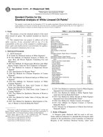
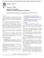
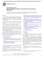
10.1.9.3 Results—The temperature change (∆T) or heat
absorption rate (J/s) in the specimen plotted against temperature shall produce a line with a clear rise in slope. The
induction temperature (degradation onset) is the intersection of
the extended base line and a line tangent to the leading slope of
the exothermic decomposition peak (see Fig. 2).
6
D3350 − 21
FIG. 2 Typical DSC Plots
at the lowest rate to the point of delivery, unless otherwise
specified in the contract or order.
11. Inspection
11.1 Inspection of the material shall be made as agreed upon
between the purchaser and the manufacturer as part of the
purchase contract.
13.2 Marking—Unless otherwise agreed upon between the
seller and the purchaser, shipping containers shall be marked
with the name of the material, identification in accordance with
this specification, the lot or batch number and quantity contained therein, as defined by the contract or order under which
shipment is made, and the name of the manufacturer.
12. Retest and Rejection
12.1 If any failure occurs, and when specified by the
manufacturer, the material shall be retested to establish conformity in accordance with the agreement between the purchaser and the manufacturer.
13.3 All packing, packaging, and marking provisions of
Practice D3892 shall apply to this specification.
13. Packaging and Marking
14. Keywords
13.1 Packaging—The material shall be packaged in standard commercial containers, so constructed as to ensure
acceptance by common or other carriers for safe transportation
14.1 cell classification system; pipe and fittings material;
polyethylene; recycled
7
D3350 − 21
SUMMARY OF CHANGES
Committee D20 has identified the location of selected changes to this standard since the last issue
(D3350 – 14) that may impact the use of this standard. (July 1, 2021)
(4) Added 6.1.1.
(5) Revised 6.5 and 6.5.2.
(1) Added 1.1.1, 1.1.2, and 1.1.3.
(2) Added Note 1 (all subsequent notes will be re-numbered).
(3) Revised 3.2.1 (all subsequent terminology entries will be
re-numbered).
ASTM International takes no position respecting the validity of any patent rights asserted in connection with any item mentioned
in this standard. Users of this standard are expressly advised that determination of the validity of any such patent rights, and the risk
of infringement of such rights, are entirely their own responsibility.
This standard is subject to revision at any time by the responsible technical committee and must be reviewed every five years and
if not revised, either reapproved or withdrawn. Your comments are invited either for revision of this standard or for additional standards
and should be addressed to ASTM International Headquarters. Your comments will receive careful consideration at a meeting of the
responsible technical committee, which you may attend. If you feel that your comments have not received a fair hearing you should
make your views known to the ASTM Committee on Standards, at the address shown below.
This standard is copyrighted by ASTM International, 100 Barr Harbor Drive, PO Box C700, West Conshohocken, PA 19428-2959,
United States. Individual reprints (single or multiple copies) of this standard may be obtained by contacting ASTM at the above
address or at 610-832-9585 (phone), 610-832-9555 (fax), or (e-mail); or through the ASTM website
(www.astm.org). Permission rights to photocopy the standard may also be secured from the Copyright Clearance Center, 222
Rosewood Drive, Danvers, MA 01923, Tel: (978) 646-2600; />
8