Astm e 1512
Bạn đang xem bản rút gọn của tài liệu. Xem và tải ngay bản đầy đủ của tài liệu tại đây (104.06 KB, 5 trang )
An American National Standard
Designation: E 1512 – 01
Standard Test Methods for
Testing Bond Performance of Bonded Anchors1
This standard is issued under the fixed designation E 1512; the number immediately following the designation indicates the year of
original adoption or, in the case of revision, the year of last revision. A number in parentheses indicates the year of last reapproval. A
superscript epsilon (e) indicates an editorial change since the last revision or reapproval.
Freezing and Thawing2
E 119 Test Methods for Fire Tests of Building Construction
and Materials3
E 488 Test Method for Strength of Anchors in Concrete and
Masonry Elements4
E 575 Practice for Reporting Data from Structural Tests of
Building Constructions, Elements, Connections, and Assemblies4
1. Scope
1.1 These test methods cover instructions for making a
variety of tests for the strength of the adhesive bond developed
between a steel anchor and the surface of a hole in concrete or
masonry (including masonry units and mortar joints) and for
assessing the effects on such bond of a variety of factors
including elevated temperature, fire, moisture, and freezing and
thawing action. The specifier or manufacturer shall select those
tests that are appropriate for the given anchoring system and
intended application.
1.2 The adhesive-bonded anchor system refers to a smooth
or deformed steel bar or threaded rod, set in a predrilled hole
containing chemical bonding compounds. Loads are transferred mainly by the bond of the adhesive both to the anchor
and the surrounding elements along the sides of the hole. For
anchoring systems made of significantly different materials,
these test methods shall be taken as a guideline.
1.3 This standard applies to all adhesives used to bond steel
anchors or steel reinforcement bars (rebar) to concrete or
masonry. These test methods apply to anchorages used in
uncracked concrete or masonry. They do not apply to the use of
the anchor in the concrete tension zone. The usual forces
applied during the tests are in tension, shear, and under a
combination of both tension and shear.
1.4 The values stated in inch-pound units are to be regarded
as the standard. The SI units given in parentheses are for
information only.
1.5 This standard does not purport to address all of the
safety concerns, if any, associated with its use. It is the
responsibility of the user of this standard to establish appropriate safety and health practices and to determine the
applicability of regulatory limitations prior to use.
3. Terminology
3.1 Definitions of Terms Specific to This Standard:
3.1.1 baseline test—restrained test conducted on anchors
installed in the same test member and under the same installation method as a required environmental test for comparison
purposes.
3.1.2 bonded anchor—a fastener placed in hardened concrete or masonry that derives its holding strength from a
chemical compound placed between the wall of the hole and
the embedded portion of the anchor.
4. Significance and Use
4.1 These test methods are intended to provide information
from which applicable design data and specifications are
derived for a given anchorage device and for qualifying
anchors or anchorage devices.
4.2 These test methods shall be followed to ensure reproducibility of the test data.
5. General Requirements
5.1 The adhesive bonded anchors to be tested shall be
representative of the product made available for typical field
installations. The manufacturer shall provide information on
physical, mechanical, and chemical properties of the anchor
system. If required by a customer or approval agency, the
testing laboratory shall verify, or have a specialized laboratory
verify, the physical, mechanical, and chemical properties of the
adhesive.
5.2 The installation equipment, instructions, and procedures
shall be as specified by the manufacturer. If there are any
2. Referenced Documents
2.1 ASTM Standards:
C 666 Test Method for Resistance of Concrete to Rapid
1
These test methods are under the jurisdiction of ASTM Committee E06 on
Performance of Buildings and are the direct responsibility of Subcommittee E06.13
on Structural Performance of Connections in Building Construction.
Current edition approved April 10, 2001. Published May 2001. Originally
published as E 1512–93. Last previous edition E 1512–93.
2
Annual Book of ASTM Standards, Vol 04.02.
Annual Book of ASTM Standards, Vol 04.07.
4
Annual Book of ASTM Standards, Vol 04.11.
3
Copyright © ASTM International, 100 Barr Harbor Drive, PO Box C700, West Conshohocken, PA 19428-2959, United States.
1
E 1512
section in question requires a specific test. A restrained test is
defined as a test conducted in accordance with Test Method
E 488 except that the test equipment support clearance requirements of E 488 do not apply. The reaction base shall be
approximately equal to the drilled hole diameter for the anchor
to preclude concrete or masonry failure, but allow bond failure.
An unrestrained test is defined as a test conducted in accordance with Test Method E 488. If the environmental tests are
conducted as restrained tests, baseline tests are required for
comparison purposes. Baseline tests are defined as restrained
tests conducted on three 1⁄2-inch (12 mm) anchors embedded
4.5 6 0.1 inches (115 6 2.5 mm) in the same base material
using the same installation method as the required environmental test. If the environmental tests are conducted as unrestrained
test, baseline tests are not required.
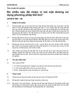
7.4.3 Test on Short-term Effect of Fire—The purpose of this
test is to determine anchor performance when subjected to the
temperatures and times given in the fire-temperature curve in
Test Method E 119. This test shall be conducted in the
unrestrained mode. Install and test a minimum of three
anchors. Use a test member that is sufficiently large (369 square
(1 m square)) to give realistic concrete or masonry response to
the fire temperature exposure in the vicinity of the test anchor.
Condition the test member in accordance with Test Method
E 119 under the “Protection and Conditioning of Test Specimen” section. A typical set-up is shown in Fig. 1. During
testing, subject the anchors to a constant tension load. This load
shall be the allowable load for the anchor as determined in
Section 7.2, or other load as specified by the manufacturer.
Maintain the load as the fire temperature is increased in
accordance with the Test Method E 119 time-temperature
curve. Record temperature and displacement readings at
1-minute increments until failure occurs.
7.4.4 Radiation Test—Perform these tests where the radiation resistance of the adhesive is required. The tests shall be
conducted as restrained tests, or unrestrained tests. If testing is
conducted in the restrained mode, baseline tests are required.
Install and test a minimum of three anchors. Expose the test
specimens to a minimum gamma radiation level of 2 3 107
rads. Conduct tension tests and compare the irradiated anchor
results to the baseline test results if the radiation tests were
conducted in the restrained mode. Compare the irradiated
anchor results to the results determined in Section 7.2 for the
same size anchor if the radiation tests were conducted in the
unrestrained mode. Upon completion of the tests, the testing
agency shall be responsible for safely disposing of the test
samples in accordance with applicable regulations.
7.4.5 Tests on Effect of Freezing and Thawing Conditions—
The tests shall be conducted as restrained tests, or unrestrained
tests. If testing is conducted in the restrained mode, baseline
tests are required. Install and test a minimum of three anchors.
Freezing-and-thawing resistant concrete shall be used as an
option. Cover the surface of the test member, within a
minimum 3-inch (76 mm) radius from the center of the test
anchor, with tap water, maintaining a minimum of 1⁄2-inch (12
mm) depth throughout the test. Load each anchor with a
constant tension load equal to at least 40 % of the ultimate load
capacity of the baseline tests for restrained tests, or 40 % of the
deviations from the manufacturer’s instructions when testing
commercial anchors, they shall be described in the report.
5.3 The structural members shall be as described in Test
Method E 488.
5.4 The test and measuring equipment for performing static
tension and shear tests, as well as dynamic tests, are described
in Test Method E 488. For performing long-term creep tests,
equipment that will sustain the required loads without distress
shall be used.
6. Materials and Manufacture
6.1 The adhesive-bonded anchors shall be installed for use
in accordance with written instructions of the manufacturer. An
inert filler that does not affect the performance of the components, if specified by the manufacturer, shall be uniformly
incorporated in one or both bonding components.
7. Procedure
7.1 This section presents the specific tests that shall be
performed as required to evaluate the bonded anchor system.
When evaluating bonded anchors in concrete, the concrete
strength shall be 3000 6 500 psi (20 6 3 MPa) compressive
strength, unless otherwise specified, using aggregate of river
gravel or crushed rock. Cure the concrete for a minimum of 28
days. Condition the test member to 75°F 6 10°F (24°C6 5°C)
prior to anchor installations, unless otherwise specified. Masonry shall be permitted to be used as the test member.
7.2 Static Tests:
7.2.1 Perform tension and shear tests in accordance with
Test Method E 488. All sizes are to be tested at both minimum
and maximum embedments expected. Shear tests at the maximum embedment shall be permitted to be excluded if shear
tests at a shallower embedment result in a steel failure. If there
is a difference greater than 9 anchor diameters between these
embedments additional intermediate embedments shall be
tested. Clean holes and install anchors as specified by the
manufacturer. Measure and record hole diameters and/or drill
bit diameters. Install and cure anchors at 75°F 6 10°F (24°C 6
5°C).
7.3 Dynamic Tests:
7.3.1 Fatigue Tests—Perform fatigue tests in accordance
with Test Method E 488.
7.3.2 Seismic Tests—Perform seismic tests in accordance
with Test Method E 488.
7.4 Environmental Tests:
7.4.1 The tests given in Sections 7.4.3-7.4.8 are designed to
determine the effect of loading and environmental influences
on the bond strength of the adhesive. To ensure bond failure,
use steel of sufficiently high strength to prevent steel failure of
the anchor. To provide comparative standardized data, anchors
shall be 1⁄29–13 UNC Threaded Rod, unless otherwise specified
(12 mm), and be embedded 4.5 6 0.1 inches (1156 2.5 mm).
Test anchors of other diameters when specified by the purchaser or manufacturer. Install and cure all anchors at 75°F 6
10°F (24°C 6 5°C), unless specified otherwise. Install and cure
anchors according to the manufacturers instructions, unless
directed otherwise.
7.4.2 The tests given in Sections 7.4.3-7.4.8 shall be conducted as restrained tests or unrestrained tests, unless the
2
E 1512
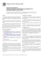
FIG. 1 Tension Creep Test Arrangement
75°F 6 10°F (24°C 6 5°C). Following the recommended cure
period, heat and maintain the specimens at the desired temperature for a minimum of 24 hours. Remove the test specimens from the heating chamber and tension test the anchors
immediately in order to assure the test specimens remain at the
conditioned temperature. A thermocouple inserted into the test
member may be used to confirm the temperature at the time of
testing. Plot a chart depicting the performance trend showing
the percentage change, compare to the strength at 70°F (21°C),
attributed to the change in temperature.
7.4.7.2 Tests on Effect of Reduced Temperature on Curing—
The tests shall be conducted as restrained tests, or unrestrained
tests. Install and test a minimum of three anchors. Prior to
installation, condition the anchor rod and test member to the
desired temperature and maintain that temperature for a minimum of 24 hours. Install the anchors and allow them to cure at
the stabilized temperature for the manufacturers recommended
cure time. Remove the test specimens from the cooling
chamber and tension test the anchors immediately in order to
assure the test specimens remain at the conditioned temperature. A thermocouple inserted into the test member may be
used to confirm the temperature at the time of testing. Compare
the results to the load obtained in Section 7.4.7.1 at 70°F
(21°C). When specific adhesives are recommended for use
below 50°F (10°C), perform the following additional test:
(a) Install and test a minimum of three anchors. Prior to
installation, condition the anchor rod and test member to the
desired temperature and maintain that temperature for a minimum of 24 hours. Install the anchors and allow them to cure at
the stabilized temperature for the manufacturer’s recommended cure time. Apply a constant tension load equal to 25 %
of the ultimate load obtained in Section 7.4.7.1 at 70°F (21°C),
then remove the test specimens from the cooling chamber.
Raise the temperature of the test member uniformly to 75°F 6
10°F (24°C 6 5°C) over a period of 72 to 96 hours while
monitoring the displacement response for each anchor. A
ultimate load capacity for the same size anchor determined in
Section 7.2 for an unrestrained test. This load is to be
maintained during the freezing and thawing cycles. The nominal freezing and thawing cycles shall consist of alternately
lowering the temperature of the chamber to −10°F (−23°C) and
holding this temperature for 3 hours, then raising the temperature to 104°F (40°C) and holding this temperature for 3 hours.
Measure the temperature at the surface of the concrete at a
location outside the standing water. At the completion of fifty
complete cycles, conduct tension tests and compare the results
to the baseline test results or to the results determined in
Section 7.2 for the same size anchor as applicable.
7.4.6 Tests on Effects of Damp Environment—The tests shall
be conducted as restrained tests, or unrestrained tests. If testing
is conducted in the restrained mode, baseline tests are required.
Install and test a minimum of three anchors. Prior to anchor
installations, fill the test holes with tap water and maintain the
water level filled for a minimum of seven days. Immediately
prior to installing the anchors, all freestanding water shall be
removed so that the walls of the test holes are surface moist.
After the appropriate cure time has elapsed, conduct tension
tests to failure and compare the results to the baseline test
results or to the results determined in Section 7.2 for the same
size anchor as applicable. If the application requires installation in water-filled holes, conduct the test as described above
except that the freestanding water is not removed. Install the
anchors in the water-filled holes.
7.4.7 Tests on Effect of Service Temperature:
7.4.7.1 Tests on Effect of Elevated Temperature on Cured
Samples—The tests shall be conducted as restrained tests, or
unrestrained tests. Install and test a minimum of three anchors
for each temperature data point. Test a sufficient number of
temperature data points to develop a load-temperature response
curve of the adhesive anchor. Test, as a minimum 70°F (21°C)
and at least four higher temperatures, one of which shall be at
least 180°F (82°C). All anchors are to be installed and cured at
3
E 1512
thermocouple inserted into the test member may be used to
confirm the temperature of the specimen during the test. Once
the test member attains the desired temperature, conduct
tension tests to failure.
7.4.8 Creep Test—The tests shall be conducted as a restrained test, or as an unrestrained test, but in either case all test
series shall be of the same type. A test series shall consist of a
minimum of three anchors. Concrete used in all test series shall
have the same mix design, and the compressive strength shall
be between 2,500 psi and 3,500 psi (17 MPa and 24 MPa) at
the time of static load tests and at initiation of creep tests, with
a minimum concrete age of 28 days. Anchors shall be cured for
7 6 5 days prior to test commencement.
7.4.8.1 Static Tension Test Series at 75°F 6 10°F (24°C 6
5°C)—A static tension load test series shall be performed at
75°F 6 10°F (24°C 6 5°C) to determine the average ultimate
tension load. Results that are less than 85 percent of the
average value shall be excluded from the determination of the
average ultimate tension load, with the average value recalculated using the remaining results.
7.4.8.2 Static Tension Test Series at Elevated
Temperature—A static tension load test series shall be performed at a minimum specified concrete temperature of 110°F
(43°C) to determine the average displacement at ultimate
tension load. The concrete temperature is established as noted
in Section 7.4.8.3 to follow. Displacement results that are
greater than 115 percent of the average value shall be excluded
from the determination of the average displacement, with the
average value re-calculated using the remaining results.
7.4.8.3 Creep Test Series at Elevated Temperature—
Thermocouples shall be embedded a minimum of 4-1⁄2 inches
(114 mm) from the surface of the concrete into which the
anchors are to be installed. The thermocouples must be cast in
place or installed into maximum 1⁄2-inch-diameter (12 mm)
holes drilled into concrete, with the holes sealed in a manner so
as to ensure that temperature readings reflect the concrete
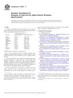
FIG. 3 Typical Fire Test Setup
temperature. After the anchor curing period, the temperature of
the specimens shall be increased until the temperature, as
determined from the thermocouples, is stabilized for at least 24
hours at the minimum elevated temperature of 110°F (43°C). A
preload not exceeding 5 percent of the sustained creep load
shall be applied before zeroing displacement readings. Sustained creep load is defined as 40 percent of the average
ultimate determined by Section 7.4.8.1 above. The remainder
of the sustained creep load shall then be applied. The initial
elastic displacement (additional displacement after the preload)
shall be measured within 3 minutes of applying the sustained
creep load. The concrete specimen temperature shall be recorded at maximum one-hour intervals. As an alternative, the
concrete specimen temperature can be recorded at maximum
24-hour intervals, provided the heat chamber temperature
necessary to maintain the required concrete temperature is
maintained and is recorded at maximum one-hour intervals.
For a smooth displacement-versus-time curve, displacements
shall be measured at least hourly for the first six hours, and
daily for the duration of the test. If the concrete test temperature falls below the minimum specified temperature (including
tolerances) for over 24 hours, the creep test duration shall be
extended to account for the total period below the minimum
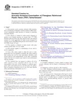
specified temperature. Creep tests shall continue for a minimum of 42 days. The total displacement at 600 days, which
includes the initial elastic displacement plus the creep displacement, is determined for each specimen by projecting a logarithmic trend line (determined by calculating a least-squares fit
through the data points, using the equation y = c ln(x) + b),
constructed from data from not less than the last 20 days
(minimum of 20 data points) of the creep test, forward to 600
FIG. 2 Tension Creep Test Arrangement Using a Dead Weight
4
E 1512
8.1.11 Amount of torque applied to anchor prior to test, if
applicable,
8.1.12 Description of test method and loading procedure
used and actual rate of loading,
8.1.13 Number of replicate samples tested,
8.1.14 Individual and average ultimate load values per
embedded anchor, standard deviation or coefficients of variation, where applicable,
8.1.15 Individual and average displacement values at ultimate loads, and load displacement curves,
8.1.16 Description of failure modes,
8.1.17 Photographs, sketches, or word descriptions of the
failure modes observed,
8.1.18 Equipment calibration certification for load cells
issued within one year prior to test dates and pressure gages
calibrated within 30 days of testing,
8.1.19 Summary of findings, and
8.1.20 Listing of observers of tests and signatures of responsible persons.
days. Compare the average total displacement at 600 days to
the average displacement determined in Section 7.4.8.2 above.
8. Report
8.1 Report the applicable information pertinent to the type
of test performed (static, fatigue, seismic, shock, etc.) and
specifically include the following:
8.1.1 Date of test and date of report,
8.1.2 Test sponsor and test agency,
8.1.3 Identification of anchors tested: manufacturer, model,
type, material, finish, shape, dimensions, and other pertinent
information,
8.1.4 Description of the anchoring system tested and description of the structural member, including dimensions and
installed reinforcing,
8.1.5 Detailed drawings or photographs of test specimens
before and after testing, if not fully described otherwise,
8.1.6 Physical strength properties of the structural member
into which the anchor or anchors are embedded, including mix
design of the concrete, compressive strength at the time of test,
and age of the structural member at the time of test,
8.1.7 Description of the procedure, tools, and materials used
to install the anchorage system and any deviations from the
recommended procedures and reason for such deviation,
8.1.8 Age, in hours or days, of the anchorage system since
installation,
8.1.9 Temperature conditions at time of installation and at
time of testing; and any other temperature experience that
affects anchor performance. For fire testing, record the timetemperature curve, average furnace temperature at failure, and
average time to which the test assemblies were exposed prior
to failure,
8.1.10 Embedment depth of installed anchors,
9. Precision and Bias
9.1 No statement is made on the precision or bias of the
procedures given in these test methods, since the test results
indicate only whether there is conformance to given criteria,
and since no generally accepted method for determining
precision and bias of these tests is currently available. General
guidelines provided herein on the specimens, instrumentation,
and procedures make the results intractable to calculation of
meaningful values by statistical analysis for precision and bias
at this time.
10. Keywords
10.1 adhesive anchors; anchors; chemical anchoring systems; concrete; masonry elements; methods of testing
The American Society for Testing and Materials takes no position respecting the validity of any patent rights asserted in connection
with any item mentioned in this standard. Users of this standard are expressly advised that determination of the validity of any such
patent rights, and the risk of infringement of such rights, are entirely their own responsibility.
This standard is subject to revision at any time by the responsible technical committee and must be reviewed every five years and
if not revised, either reapproved or withdrawn. Your comments are invited either for revision of this standard or for additional standards
and should be addressed to ASTM Headquarters. Your comments will receive careful consideration at a meeting of the responsible
technical committee, which you may attend. If you feel that your comments have not received a fair hearing you should make your
views known to the ASTM Committee on Standards, at the address shown below.
This standard is copyrighted by ASTM, 100 Barr Harbor Drive, PO Box C700, West Conshohocken, PA 19428-2959, United States.
Individual reprints (single or multiple copies) of this standard may be obtained by contacting ASTM at the above address or at
610-832-9585 (phone), 610-832-9555 (fax), or (e-mail); or through the ASTM website (www.astm.org).
5