Tieu chuan phun vay aci 506r 05
Bạn đang xem bản rút gọn của tài liệu. Xem và tải ngay bản đầy đủ của tài liệu tại đây (714.02 KB, 40 trang )
daneshlink.com
ACI 506R-05
Guide to Shotcrete
Reported by ACI Committee 506
John H. Pye
Chair
Dudley R. Morgan
Secretary
Jon B. Ardahl
Hugo Armelin
I. Leon Glassgold*
Jill E. Glassgold
H. Celik Ozyildirim
Harvey Parker
W. L. Snow, Sr.
Randy South
Lars F. Balck, Jr.†
Michael Ballou
Warren Harrison
Merlyn Isaak
Jeffrey Pool
James A. Ragland
Peter C. Tatnall
Lawrence J. Totten
Nemkumar Banthia
Denis Beaupre
Marc Jolin
Pierre Lacombe
Venkataswamy Ramakrishnan
Paul E. Reinhart
Ransom C. White, Jr.
Peter T. Yen
Chris Breeds
Jean-Francois Dufour
Albert Litvin
Kristian Loevlie
Raymond J. Schutz
Philip T. Seabrook
George Yoggy
Christopher M. Zynda
Steven Gebler
__________
*
Deceased
Subcommittee chair who produced this report.
†
This guide provides information on materials and properties of both
dry-mix and wet-mix shotcrete. Most facets of the shotcrete process are
covered, including application procedures, equipment requirements, and
responsibilities of the shotcrete crew. Other aspects, such as preconstruction
trials, craftsman qualification tests, materials tests, and finished shotcrete
acceptance tests, are also discussed.
Keywords: dry-mix shotcrete; mixture proportion; placing; quality control;
shotcrete; wet-mix shotcrete.
--`,`,,```,,`,```,`,`,```,``,,,,-`-`,,`,,`,`,,`---
CONTENTS
Chapter 1— General, p. 506R-2
1.1—Introduction
1.2—Scope
1.3—History
1.4—Definitions
1.5—Shotcreting processes
1.6—Properties
1.7—Shotcrete applications
1.8—New developments and potential future uses
ACI Committee Reports, Guides, Standard Practices, and
Commentaries are intended for guidance in planning,
designing, executing, and inspecting construction. This
document is intended for the use of individuals who are
competent to evaluate the significance and limitations of its
content and recommendations and who will accept
responsibility for the application of the material it contains.
The American Concrete Institute disclaims any and all
responsibility for the stated principles. The Institute shall not
be liable for any loss or damage arising therefrom.
Reference to this document shall not be made in contract
documents. If items found in this document are desired by the
Architect/Engineer to be a part of the contract documents, they
shall be restated in mandatory language for incorporation by
the Architect/Engineer.
Copyright American Concrete Institute
Provided by IHS under license with ACI
No reproduction or networking permitted without license from IHS
Chapter 2—Materials, p. 506R-9
2.1—Introduction
2.2—Delivery, handling, and storage
2.3—Cement
2.4—Aggregate
2.5—Water
2.6—Bonding compounds
2.7—Admixtures
2.8—Reinforcement
2.9—Curing and form coating compounds
Chapter 3—Equipment, p. 506R-11
3.1—Introduction
3.2—Dry-mix equipment
3.3—Wet-mix equipment
3.4—Air requirements
3.5—Mixing equipment
3.6—Hoses
3.7—Nozzles
3.8—Auxiliary equipment
3.9—Plant layout and operation
3.10—Other uses of shotcrete equipment
3.11—Safety
Chapter 4—Crew organization, p. 506R-18
4.1—Introduction
4.2—Composition and duties
ACI 506R-05 supersedes ACI 506R-90 (Reapproved 1995) and became effective
October 7, 2005.
Copyright © 2005, American Concrete Institute.
All rights reserved including rights of reproduction and use in any form or by any
means, including the making of copies by any photo process, or by electronic or
mechanical device, printed, written, or oral, or recording for sound or visual reproduction
or for use in any knowledge or retrieval system or device, unless permission in writing
is obtained from the copyright proprietors.
506R-1
Licensee=University of Texas Revised Sub Account/5620001114, User=wer, weqwe
Not for Resale, 01/26/2015 02:05:31 MST
Daneshlink.com
daneshlink.com
506R-2
ACI COMMITTEE REPORT
4.3—Crew qualifications
4.4—Communications
Chapter 5—Preliminary procedures, p. 506R-20
5.1—Introduction
5.2—Surface preparation
5.3—Formwork
5.4—Reinforcement
5.5—Anchors
5.6—Alignment control
5.7—Joints
5.8—Protection of adjacent surfaces
--`,`,,```,,`,```,`,`,```,``,,,,-`-`,,`,,`,`,,`---
Chapter 6—Proportioning and preconstruction
testing, p. 506R-24
6.1—Introduction
6.2—Performance versus prescription specification
6.3—Proportioning of shotcrete mixture
6.4—Preconstruction testing
Chapter 7—Batching and mixing, p. 506R-26
7.1—Introduction
7.2—Batching
7.3—Mixing
Chapter 8—Shotcrete placement, p. 506R-27
8.1—Introduction
8.2—Special applications and mixtures
8.3—Preliminary procedures
8.4—Shotcrete equipment procedures
8.5—Application of shotcrete
8.6—Finishing
8.7—Tolerances
8.8—Curing
8.9—Hot-weather shotcreting
8.10—Cold-weather shotcreting
8.11—Hazards
Chapter 9—Quality control, p. 506R-35
9.1—Introduction
9.2—Design and quality control
9.3—Materials
9.4—Application equipment
9.5—Craftsmanship
9.6—Placement techniques
9.7—Inspection
9.8—Testing procedures
Chapter 10—References, p. 506R-36
10.1—Referenced standards and reports
10.2—Cited references
Appendix—Payment for shotcrete work, p. 506R-38
A.1—Introduction
A.2—Payment methods
A.3—Factors affecting payment
A.4—Supplementary items
A.5—Methods of measurement
A.6—Pay items
Copyright American Concrete Institute
Provided by IHS under license with ACI
No reproduction or networking permitted without license from IHS
CHAPTER 1—GENERAL
1.1—Introduction
Shotcrete has grown into an important and widely used
construction technique. Because of continuing research and
development in materials, equipment, and construction
procedures, this guide is revised periodically to reflect
current industry practice. The guide was originally prepared
to replace “Recommended Practice for Shotcreting” (ACI
506-66, Revised 1983).
1.2—Scope
This guide, based on many years of practice and experience, covers aspects of shotcrete construction including
materials, equipment, crew organization, preliminary preparation, proportioning, shotcrete placement, and quality
control. New construction, repair, linings, coatings, refractories, underground support, and other special applications are
also discussed. An appendix on suggested methods of
payment is included. Procedures vary from one region to
another, and adjustments may be required to meet the needs
of a particular project. No attempt is made to provide guidelines for the design of shotcrete installations.
1.3—History
In 1910, a double-chambered cement gun, based on a
design developed by Carl Akeley, was introduced to the
construction industry. The sand-cement product produced by
this device was given the proprietary name Gunite. In the
ensuing years, trademarks such as Guncrete, Pneucrete,
Blastcrete, Blocrete, Jetcrete, and the terms “pneumatically
applied mortar or concrete” and “sprayed concrete” were
introduced to describe similar processes. The early 1930s
saw the generic term “shotcrete” introduced by the American
Railway Engineering Association to describe the Gunite
process. In 1951, the American Concrete Institute adopted
the term “shotcrete” to describe the dry-mix process. It is
now also applied to the wet-mix process and has gained
widespread acceptance in the United States and around the
world (ACI Committee 506 1966).
The 1950s saw the introduction of dry-mix guns, which
applied mixtures containing coarse aggregate; wet-mix shotcrete
equipment; and the rotary gun, a continuous feed device. Many
improvements were made to wet-mix equipment and materials
in the 1970s and 1980s. These improvements allowed pumping
low-slump concrete longer distances at greater volumes.
These innovations enhanced the utility, flexibility, and general
effectiveness of the process. The development of centrifugally
applied concrete and low-pressure, low-velocity wet-process
mortar and concrete are not considered shotcrete in this guide
because they do not comply with the current definition of
shotcrete or they do not achieve sufficient compaction (ACI
Compilation No. 6 1987).
1.4—Definitions
The following definitions cover terms used in shotcreting:
air ring—a perforated manifold in the nozzle of wet-mix
shotcrete equipment through which high-pressure air is
introduced into the material flow.
Licensee=University of Texas Revised Sub Account/5620001114, User=wer, weqwe
Not for Resale, 01/26/2015 02:05:31 MST
Daneshlink.com
daneshlink.com
GUIDE TO SHOTCRETE
air-water jet—a high-velocity jet of air and water used for
scouring surfaces in preparation for the next layer of shotcrete.
alignment wire—see ground wire.
blowpipe—air jet operated by a nozzle operator’s helper
in shotcrete shooting to assist in keeping rebound or other
loose material out of the work. Also known as an air lance.
buildup—thickness of the freshly applied shotcrete.
bulking—increase in volume of sand in a moist condition
over the same quantity in a dry condition.
brooming—a finishing procedure in which a broom is
pulled across the shotcrete surface to roughen the surface.
coarse-aggregate shotcrete—shotcrete with a nominal
coarse-aggregate size larger than 1/4 in. (5 mm).
collated fiber—fibers bundled together either by crosslinking or by chemical or mechanical means.
conventional shotcrete—shotcrete composed only of
portland cement and normalweight aggregates.
conveying hose—see delivery hose.
cutting screed—sharp-edged tool used to trim shotcrete to
finish outline; see also rod.
cuttings—shotcrete material that has been applied beyond
the finish face and is cut off in the trimming or rodding
process.
delivery equipment—equipment that introduces shotcrete
material into the delivery hose.
delivery hose—hose through which shotcrete materials
pass on their way to the nozzle; also known as material hose
or conveying hose.
dry-mix shotcrete—shotcrete in which most of the
mixing water is added at the nozzle.
entrained air—microscopic air bubbles intentionally
incorporated in mortar or concrete during mixing, usually by
use of a surface-active agent; typically between 0.0004 in.
(10 µm) and 0.04 in. (1 mm) in diameter and spherical or
nearly so.
entrapped air—air voids in concrete that are not
purposely entrained and are significantly larger than 0.04 in.
(1 mm), or larger in size than entrained air voids and are not
contributory to resisting freezing-and-thawing action.
feed wheel—material distributor or regulator in certain
types of shotcrete delivery equipment.
fiber—short, discrete pieces of steel or synthetic material
added to shotcrete as reinforcement.
finish coat—final thin coat of shotcrete preparatory to
hand finishing; see also flash coat.
finisher—craftsman that trims and finishes the surface of
the shotcrete; see also rodman.
flash coat—thin shotcrete coat applied from a distance
greater than normal for use as a final coat or for finishing;
also called flashing.
ground wire—small-gauge, high-strength steel wire used
to establish line and grade for shotcrete work; also called
alignment wire, screed wire, or shooting wire.
gun—dry-mix shotcrete delivery equipment.
gun finish—undisturbed final layer of shotcrete as applied
from a nozzle without hand finishing.
gun operator—craftsman on dry-mix shotcreting crew who
operates delivery equipment.
--`,`,,```,,`,```,`,`,```,``,,,,-`-`,,`,,`,`,,`---
Copyright American Concrete Institute
Provided by IHS under license with ACI
No reproduction or networking permitted without license from IHS
506R-3
gunite—term sometimes used for dry-mix shotcrete.
gunning—the act of applying shotcrete; shotcreting.
Hamm tip—a flared shotcrete nozzle with a larger diameter at midpoint than either inlet or outlet.
hydronozzle—a special prewetting and mixing nozzle
consisting of a short length of delivery hose inserted between
the nozzle body and nozzle tip; also called premixing nozzle.
impact velocity—the velocity of the material particles just
before impact.
laitance—a layer of weak and nondurable material
containing cement and fines from aggregates, brought by
bleeding water to the surface of overwet shotcrete; the
amount is generally increased by overworking or overmanipulating concrete at the surface by improper finishing
or by job traffic.
lance—an extended nozzle of various configurations
consisting of a length of metal pipe with nozzle and body (or
bodies) used to shoot shotcrete refractory material in areas of
elevated temperature.
material hose—see delivery hose.
nozzle—attachment at end of delivery hose from which
shotcrete is projected at high velocity.
nozzle body—a device at the end of the delivery hose that
has a regulating valve and contains a manifold (water or air
ring) to introduce water or air to the shotcrete mixture; a
nozzle tip is attached to the exit end of the nozzle body.
nozzle liner—replaceable insert in nozzle tip, usually
rubber, to reduce wear.
nozzle operator—craftsman on shotcrete crew who
manipulates the nozzle, controls consistency with the dry
process, and controls final deposition of the material.
nozzle velocity—the velocity of shotcrete material particles at
exit from nozzle, in ft/s (m/s).
overspray—shotcrete material deposited away from
intended receiving surface.
pass—distribution of stream of materials over the receiving
surface during shotcreting. A layer of shotcrete is built up by
making several passes.
pneumatic feed—shotcrete delivery equipment in which a
pressurized air stream conveys material.
pneumatically applied concrete—see shotcrete.
pneumatically applied mortar—see shotcrete.
positive displacement—wet-mix shotcrete delivery
equipment in which a pump or other nonpneumatic means
pumps the material through the delivery hose in a solid mass.
predampening—in the dry-mix process, adding water to
the aggregate before mixing to bring its moisture content to
a specified amount, usually 3 to 6%.
prewetting—in the dry-mix process, adding a portion of
mixing water to shotcrete materials in the delivery hose at
some distance before the nozzle.
puddling—placement of shotcrete where air pressure is
decreased and water content is increased, usually an undesirable
method of shotcreting.
pump—wet-mix delivery equipment.
pump operator—craftsman on wet-mix shotcreting crew
who operates delivery equipment.
Licensee=University of Texas Revised Sub Account/5620001114, User=wer, weqwe
Not for Resale, 01/26/2015 02:05:31 MST
Daneshlink.com
daneshlink.com
ACI COMMITTEE REPORT
rebound—shotcrete that bounces away from the surface
against which the shotcrete is being projected.
rod—sharp-edged cutting screed used to trim shotcrete to
forms or ground wires.
rodman—craftsman on the shotcrete crew who uses a rod
or other tools to trim and finish the shotcrete.
rolling—result of applying shotcrete at angles less than
90 degrees to the receiving surface, resulting in an uneven,
wavy, textured surface at the outer edge of spray pattern.
sagging—see sloughing.
sand lens—see sand pocket.
sand pocket—a zone in the shotcrete containing fine
aggregate with little or no cement.
scratch coat—shotcrete layers that are placed before the
finish coat.
screed wire—see ground wire.
shadow—the area behind an obstacle that is not
adequately impacted and compacted by the shotcrete stream.
In hardened shotcrete, shadow refers to any porous area
behind an obstacle such as reinforcement.
shooting—act of applying shotcrete; see also gunning.
shotcrete—mortar or concrete pneumatically projected at
high velocity onto a surface.
sloughing—subsidence of shotcrete, generally due to
excessive water in the mixture; also called sagging.
slugging—pulsating or intermittent flow of shotcrete
material.
water ring—a perforated manifold in the nozzle body of
dry-mix shotcrete equipment through which water is added
to the materials.
w/cm—water-to-cementitious material ratio.
wet-mix shotcrete—shotcrete in which all of the ingredients,
including water, are mixed before introduction into the
delivery hose; compressed air is introduced to the material
flow at the nozzle.
wetting—in the dry-mix process, the addition of mixing
water to shotcrete materials just before the material exits the
nozzle.
1.5—Shotcreting processes
Shotcreting is classified according to the process used
(wet-mix or dry-mix) and the size of aggregate used (coarse
or fine). Refer to Table 1.1 for fine-aggregate grading (No.
1) and coarse-aggregate grading (No. 2).
1.5.1 Dry-mix process—The dry-mix process consists of
five steps:
1. All ingredients, except water, are thoroughly mixed;
2. The cementitious-aggregate mixture is fed into a special
mechanical feeder or gun called the delivery equipment;
3. The mixture is usually introduced into the delivery hose
by a metering device such as a feed wheel, rotor, or feed
bowl. Some equipment use air pressure alone (orifice feed)
to deliver the material into the hoses;
4. The material is carried by compressed air through the
delivery hose to a nozzle body. The nozzle body is fitted inside
with a water ring, through which water is introduced under
pressure and thoroughly mixed with the other ingredients; and
Copyright American Concrete Institute
Provided by IHS under license with ACI
No reproduction or networking permitted without license from IHS
Table 1.1—Grading limits for combined aggregates
Sieve size, U.S.
standard square mesh
Percent by weight passing individual sieves
Grading No. 1
Grading No. 2
3/4 in. (19 mm)
1/2 in. (12 mm)
—
—
—
100
3/8 in. (10 mm)
No. 4 (4.75 mm)
100
95 to 100
90 to 100
70 to 85
No. 8 (2.4 mm)
No. 16 (1.2 mm)
80 to 98
50 to 85
50 to 70
35 to 55
No. 30 (600 µm)
No. 50 (300 µm)
25 to 60
10 to 30
20 to 35
8 to 20
No. 100 (150 µm)
2 to 10
2 to 10
Table 1.2—Comparison of dry-mix and wet-mix
processes
Dry-mix process
Wet-mix process
1. Instantaneous control over 1. Mixing water is controlled at the
mixing water and consistency of mixing equipment and can be
the mixture at the nozzle to meet accurately measured.
variable field conditions.
2. Better assurance that the mixing
2. Better suited for placing water is thoroughly mixed with
mixtures containing lightweight other ingredients.
aggregates or refractory materials.
3. Less dust and cementitious
3. Capable of being transported materials lost during the shooting
operation.
longer distances.
4. Delivery hoses are easier to 4. Normally has lower rebound,
resulting in less waste.
move.
5. Lower volume per hose size.
5. Higher volume per hose size.
--`,`,,```,,`,```,`,`,```,``,,,,-`-`,,`,,`,`,,`---
506R-4
5. The material is jetted from the nozzle at high velocity
onto the surface to be shotcreted.
1.5.2 Wet-mix process—The wet-mix process consists of
five steps:
1. All ingredients, including mixing water, are thoroughly
mixed;
2. The mortar or concrete is introduced into the chamber
of the delivery equipment;
3. The mixture is metered into the delivery hose and
moved by positive displacement or conveyed by compressed
air to a nozzle;
4. Compressed air is injected at the nozzle to increase
velocity and improve the shooting pattern; and
5. The mortar or concrete is jetted from the nozzle at high
velocity onto the surface to be shotcreted.
1.5.3 Comparison of the processes—Either process can
produce shotcrete suitable for normal construction requirements.
Differences in capital and maintenance cost of equipment,
operational features, suitability of available aggregate, and
placement characteristics, however, may make one or the
other more attractive for a particular application. Table 1.2
gives differences in operational features and other properties that
may merit consideration.
1.5.4 Coarse-aggregate shotcrete—There are four reasons
for adding coarse aggregate to shotcrete:
1. The reduced surface area of coarse aggregate versus fine
aggregate permits lower water content;
2. Coarse aggregate reduces drying shrinkage by reducing
fine aggregate content;
Licensee=University of Texas Revised Sub Account/5620001114, User=wer, weqwe
Not for Resale, 01/26/2015 02:05:31 MST
Daneshlink.com
daneshlink.com
GUIDE TO SHOTCRETE
506R-5
--`,`,,```,,`,```,`,`,```,``,,,,-`-`,,`,,`,`,,`---
3. The addition of coarse aggregate may improve pumpability
for wet-mix;
4. The impact of coarse aggregate into plastic shotcrete
improves the in-place density; and
5. The economy of the mixture may be improved.
For both the dry-mix and wet-mix processes, however,
coarse-aggregate shotcrete with more than 30% coarse
aggregate has greater rebound, is more difficult to finish, and
cannot be used for thin layers. Coarse-aggregate shotcrete
requires the use of a larger-diameter hose and creates craters
in the plastic shotcrete when shot at high velocity.
Table 1.3—Influence of surface preparation on
tensile bond strength, psi (MPa)
1.6—Properties
There are many different types of mixtures applied by
shotcreting, including plain, silica fume, fiber-reinforced,
high-strength, and high-performance. The different types
have different hardened properties.
The mixture composition should be such that the in-place
hardened shotcrete will develop acceptable mechanical and
physical properties. As a general rule, the mixture composition
will affect hardened shotcrete properties in the same way as
normal concrete. Effects associated with the shooting
process, such as compaction, rebound, and fiber orientation,
however, may affect the hardened shotcrete properties
(Lorman 1968).
The w/cm is the key parameter for wet-mix shotcrete, as is
the initial cement-aggregate ratio for dry-mix shotcrete.
Reducing the w/cm enhances most properties of shotcrete,
including strength, permeability, and durability. The presence
of accelerators, silica fume, or other pozzolans modifies
physical properties, especially permeability and durability.
The use of an air-entraining admixture improves shotcrete’s
resistance to freezing and thawing, while the use of fibers
improves toughness. As with normal cast-in-place concrete,
proper curing is important and always improves the mechanical
and physical performance of shotcrete.
High-performance shotcrete, which can include properties
such as high compressive strength, low permeability, high
durability, and heat or chemical resistance, can be achieved
with special admixtures and materials such as silica fume.
1.6.1 Compressive strength—The compressive strength of
dry-mix shotcrete depends to a large extent on the cementaggregate ratio. Compressive strengths up to 12,000 psi
(85 MPa) can be produced while strengths of 6000 to 7000 psi
(40 to 50 MPa) are common.
Reducing the w/cm, using high-range water-reducing
admixtures, and adding silica fume can produce highstrength wet-mix shotcrete. Strengths over 14,000 psi (100 MPa)
have been reported for dry-mix. Usually the strength of wet-mix
shotcrete is between 4000 and 7000 psi (30 to 50 MPa).
Early-age strength development is often more important
than the ultimate strength in rehabilitation work, tunnels, and
underground supports. In these cases, accelerators are often
used to improve early strength development. They may,
however, reduce long-term strength, even as early as 28 days,
and durability compared with a non-accelerated shotcrete of
the same composition. These effects are usually proportional
to the accelerator dosage, or are affected by the chemical
composition of accelerators (Gebler et al. 1997; Jolin et al.
1997; Schutz 1982).
1.6.2 Flexural properties—Traditionally, welded-wire
fabric was used in shotcrete tunnel linings to provide ductility
to the shotcrete lining. Now welded-wire reinforcement is
increasingly being replaced by steel or synthetic fibers. Fiber
reinforcement gives shotcrete toughness and load-bearing
capacity after cracking. It also helps control restrained
shrinkage cracking and improves impact resistance. Postcracking behavior can be evaluated by flexural toughness
tests such as ASTM C 1018.
1.6.3 Bond strength—Because shotcrete is physically
driven onto the receiving surface, it usually exhibits good
bond with concrete, masonry, rock, steel, and many other
materials. Bond strength is usually measured by shear or
direct tension using a pull-off test. Shotcrete should develop
a minimum tensile bond strength of 100 psi (0.7 MPa).
Properly applied shotcrete with sufficient compaction on a
well-prepared substrate usually develops a bond strength of
over 145 psi (1 MPa).
Bond-strength test results for measurements for dry-mix
and wet-mix shotcrete conducted on different prepared
concrete substrates indicated that the mixture composition of
shotcrete has less influence on bond than surface preparation.
Best results were obtained with hydromilling, sandblasting
alone, or chipping with chipping hammers followed by sandblasting (Table 1.3). The other types of surface preparation
(grinding, chipping with chipping hammers without sandblasting) resulted in either lower bond strength or a reduction
in bond durability (reduction of bond strength with time). The
moisture condition of the substrate at the time of application
of the shotcrete is also important. Best bond is achieved on a
saturated surface-dry substrate. Excessively dry or wet
substrate surfaces at the time of shotcrete application reduce
bond strength. Brooming between layers of shotcrete breaks
up laitance, removes or imbeds overspray, and these practices
improve bond. It is also important that the substrate surface be
kept clean between applications (Talbot et al. 1994).
1.6.4 Shrinkage—Shrinkage is an important parameter with
respect to potential cracking and bond durability, especially if
shotcrete is used to repair concrete structures. The drying
shrinkage of shotcrete varies with the mixture proportion, but
generally falls within the range of 0.06 and 0.10% at 3 months,
as measured by ASTM C 157. Shrinkage is typically greater
in shotcrete than most conventional concretes, mainly because
shotcrete has less coarse aggregate and more cementitious
Copyright American Concrete Institute
Provided by IHS under license with ACI
No reproduction or networking permitted without license from IHS
Type of
shotcrete
Dry-mix
Dry-mix +
silica fume +
fibers
Wet-mix
Hydromilling*
SandChipping and
blasting Grinding Chipping sandblasting
230 (1.6) 290 (2.0) 30 (0.2)
190 (1.3)
245 (1.7)
290 (2.0) 290 (2.0) 115 (0.8) 160 (1.1)
275 (1.9)
230 (1.6)
—
—
—
—
*The
surface was prepared by hydromilling to remove the surface skin of concrete.
Notes: Results are a compilation of bond test from several projects. Most failures
occurred in the substrate concrete. There were 18 tests, and the average tensile bond
strength was 200 psi (1.5 MPa).
Licensee=University of Texas Revised Sub Account/5620001114, User=wer, weqwe
Not for Resale, 01/26/2015 02:05:31 MST
Daneshlink.com
daneshlink.com
506R-6
ACI COMMITTEE REPORT
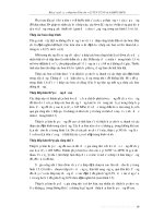
Fig. 1.1—Elevated prestressed shotcrete water storage tank.
material and water. The use of accelerators tends to increase
shrinkage and the potential for cracking.
1.6.5 Resistance to freezing and thawing—There are many
references and compilations concerning shotcrete durability,
especially freezing-and-thawing resistance of shotcrete and
salt-scaling resistance of shotcrete (Beaupre et al. 1994;
Glassgold 1989; Morgan et al. 1988; Seegebrecht et al. 1989).
The freezing-and-thawing resistance of shotcrete, as it is for
normal concrete, is strongly dependent on the w/cm and on the
quality of the air void system, especially the entrained-air-void
content and spacing factor determined in accordance with
ASTM C 457.
Critically saturated wet-mix shotcrete requires an entrained
air-void system with a minimum air content of 4% with a
maximum air void spacing factor of 0.001 in. (0.30 mm) to
resist rapid freezing-and-thawing cycles (ASTM C 666).
Wet-mix shotcrete is normally only resistant to deicer salt
scaling (ASTM C 672) if an air-entraining admixture is used
and if the in-place w/cm is less than 0.45.
When wet-mix shotcrete is placed, the majority of
entrained air is lost during shooting. To have sufficient
entrained air in the in-place material per the committee’s
consensus, wet-mix shotcrete should have a minimum air
content of 6% before shooting. Testing of in-place air
content is done in accordance with ASTM C 173 or C 231.
Dry-mix shotcrete, when tested for resistance to rapid
freezing and thawing per ASTM C 666, has demonstrated
--`,`,,```,,`,```,`,`,```,``,,,,-`-`,,`,,`,`,,`---
Copyright American Concrete Institute
Provided by IHS under license with ACI
No reproduction or networking permitted without license from IHS
good durability, especially when air entrained. For the dry-mix
process, it is possible to improve the quality of the air-void
system by adding an air-entraining admixture to the mixing
water or adding a dry, powdered, air-entraining admixture to
the mixture.
1.6.6 Absorption and volume of permeable voids—The
absorption test (ASTM C 642) may be conducted on hardened
shotcrete to provide an overall indication of the quality of the
shotcrete, especially in dry-mix shotcrete where the results are
largely influenced by the w/cm. The absorption value and
the volume of permeable voids are useful in identifying
poorly compacted shotcrete or shotcrete with a weak or
damaged microstructure.
Acceptable values of permeable void volume range from
14 to 17%. Typical boiled absorption values are 6 to 9%.
Results vary depending on the absorptive characteristics of
the aggregate. Lightweight aggregate has high absorption.
The absorption of a shotcrete specimen is usually proportional
to its w/cm. A low w/cm will yield a relatively low volume of
permeable voids or low absorption values, which is an indication
of a good quality shotcrete. A mixture shot too dry, however, will
yield a relatively high volume of permeable voids or high
absorption values due to the stiffness of the plastic shotcrete.
Impact velocity is another important parameter that influences
the porosity of the hardened shotcrete. Insufficient impact
velocity will not provide adequate compaction, resulting in high
permeability and high absorption values.
Set accelerators may have a detrimental effect on the
porosity of shotcrete, usually due to the flash-setting effect
of the admixture, which diminishes the self-compacting
effect of shotcrete. The influence of different accelerators,
however, will vary (Section 2.7.1) and should be checked
with test panels before use in production.
In general, high values of permeable voids or absorption
usually indicate poor quality and reduced durability of the
in-place shotcrete.
1.6.7 Other properties—Permeability varies according to the
mixture composition (w/cm and silica fume). Shotcrete and
concrete have similar coefficients of permeability for given
constituent materials and w/cm. The coefficient of thermal
expansion of shotcrete is approximately that of reinforcing steel,
thereby minimizing internal stress development. The density of
high-quality shotcrete is usually between 139 to 149 lb/ft3
(2230 and 2390 kg/m3), similar to conventional concrete. The
modulus of elasticity is between 2.4 to 5.8 × 10⁶ psi (17 to
40 GPa), again similar to conventional concrete.
1.7—Shotcrete applications
Shotcrete can be used instead of conventional concrete in
many instances, the choice being based on convenience and
cost. Shotcrete offers advantages over conventional concrete in
a variety of new construction and repair work (Fig. 1.1 and 1.2).
Reinforcement details may complicate the use of shotcrete,
but shotcrete is particularly cost effective where formwork is
impractical or where forms can be reduced or eliminated;
access to the work area is difficult; thin layers, variable
thickness, or both are required; or normal casting techniques
cannot be employed. The excellent bond of shotcrete
Licensee=University of Texas Revised Sub Account/5620001114, User=wer, weqwe
Not for Resale, 01/26/2015 02:05:31 MST
Daneshlink.com
daneshlink.com
GUIDE TO SHOTCRETE
506R-7
Fig. 1.2—Dry-mix shotcrete lining being installed in a large
water irrigation channel in Arizona.
Fig. 1.4—Applying steel fiber-reinforced dry-mix shotcrete
against a rock.
Fig. 1.3—Applying wet-mix shotcrete: (a) as scour protection to
a spawning channel; and (b) in a swimming pool.
--`,`,,```,,`,```,`,`,```,``,,,,-`-`,,`,,`,`,,`---
Copyright American Concrete Institute
Provided by IHS under license with ACI
No reproduction or networking permitted without license from IHS
(Table 1.3) to a number of materials is sometimes an important
design consideration.
Shotcrete applications can be classified under three
general headings:
1. Conventional (standard typical use)—using portland
cement, conventional aggregates, and ordinary admixtures
where appropriate;
2. Refractory (high temperatures)—using high-temperature
binders and refractory aggregates; and
3. Special (for interface bond enhancement)—using
proprietary combinations of binder and aggregate or
conventional shotcrete with special admixtures.
1.7.1 Conventional shotcrete—Conventional shotcrete
(shotcrete without special admixtures) is the most commonly
used application for shotcrete and includes the following:
• New structures—roofs, thin shells, walls, prestressed
tanks, buildings, reservoirs, canals, swimming pools,
boats, sewers, foundation shoring, ductwork, shafts,
and artificial rock (Fig. 1.3(a) and (b));
• Linings and coatings—over brick, masonry, earth, and
rock; underground support, tunnels, slope protection,
erosion control, fireproofing of steel, steel pipeline,
stacks, hoppers, bunkers, steel, wood, and concrete; pipe
protection, and structural steel encasement (Fig. 1.4);
• Repair—for deteriorated concrete in bridges, culverts,
sewers, dams, reservoir linings, grain elevators,
tunnels, shafts, waterfront structures, buildings, tanks,
piers, seawalls, brick, masonry, and steel structures
(Fig. 1.5(a) and (b));
Licensee=University of Texas Revised Sub Account/5620001114, User=wer, weqwe
Not for Resale, 01/26/2015 02:05:31 MST
Daneshlink.com
daneshlink.com
506R-8
ACI COMMITTEE REPORT
procedures for high-temperature installation and “bench”
shooting for thick layers has opened new fields for refractory
shotcrete use.
1.7.3 Special shotcrete—Special shotcretes include
proprietary mixtures for corrosion- and chemical-resistant
applications. Portland cement with admixtures or other types
of cements are used to produce special corrosion- and chemicalresistant properties. Special cements include magnesium
phosphates cements and calcium aluminate cement.
Polymer-modified shotcrete is also sometimes used.
Special shotcretes find application in caustic and acid
storage basins, chimneys and stacks, process vessels, chemical
spillage areas, sumps, trenches, pollution control systems, and
concrete repair in other highly aggressive environments.
Fig. 1.5—(a) Deteriorated double-box culvert showing
advanced deterioration and distress before repair; and (b)
concrete in culvert restored with shotcrete with natural or
gun finish.
•
Strengthening and reinforcing—to strengthen and
reinforce concrete beams, columns, slabs, concrete
and masonry walls, steel stacks, tanks, and pipes. Shotcrete
is also used for seismic rehabilitation of shearwalls,
boundary elements, beams, columns, overhead joists,
and slabs, and for strengthening of existing masonry
and concrete walls. Shotcrete is used in structural
interiors and exteriors because of its speed and flexibility
of application; and
• Ground support—extensively as temporary and permanent ground support. It has become the primary method
of ground support in tunnels and mines (ACI/ASCE
1976; Ward and Hills 1977). It is also used extensively as
lagging instead of wood for soldier pile and lagging
shoring systems, and is the lagging in soil nailing.
1.7.2 Refractory shotcrete—Shotcrete applications in
refractory construction began in the mid 1920s where it was
used primarily for repair and maintenance of furnace linings.
The refractory industry favors shotcrete because of the speed
of installation and general effectiveness of the process. Shotcrete
has become a major method of installation for all types of
linings from several inches to several feet thick. It is used in
new construction and for repair and maintenance in steel and
nonferrous metal; chemical, mineral, and ceramic processing
plants; steam power plants; and incinerators.
Refractory shotcrete provides a viable alternate to
traditional methods of refractory construction. Hot gunning
--`,`,,```,,`,```,`,`,```,``,,,,-`-`,,`,,`,`,,`---
Copyright American Concrete Institute
Provided by IHS under license with ACI
No reproduction or networking permitted without license from IHS
1.8—New developments and potential future uses
1.8.1 General—The future of shotcrete is limited only by
the speed of development of new materials, equipment, and
techniques. A prime example of major expansion in the use
of shotcrete is in early and final lining ground support in
tunnels and mines. Improvements in prepackaged products,
accelerating and setting-control admixtures, the use of
fibers, and specially designed equipment, including robot
and remote control shotcrete devices, have spurred the
development of ground support techniques competitive with
conventional rock bolt and mesh and steel rib supports (ACI/
ASCE 1974).
1.8.2 Fiber-reinforced shotcrete—The addition of steel or
synthetic fibers in conventional and refractory shotcrete has
been gaining favor during the past two decades. The fibers at
normal addition rates can provide improved flexural and shear
toughness, and impact resistance. For refractory shotcrete,
stainless steel fibers increase resistance to thermal shock,
temperature cycling damage, and crack development. Some
specific applications where fiber-reinforced shotcrete can be
cost effective are slope protection (Fig. 1.4), ground support in
tunnels and mines, concrete repair, swimming pools, thin shell
configurations, and refractory applications such as boilers,
furnaces, coke ovens, and petrochemical linings.
Synthetic fibers may reduce the susceptibility of shotcrete
to plastic shrinkage cracking. At higher addition rates, they
can also improve flexural toughness (ASTM C 1018). Shotcrete
builds up as multiple thin layers with each succeeding
layer flattening the previous layer, which causes fibers to lay
roughly parallel to the surface so they are more effective than the
random distribution that occurs in fiber-reinforced concrete.
Fibers may have larger rebound than normal aggregate
rebound, particularly in dry-mix shotcrete. As the aggregate
rebound increases, the amount of fiber rebounding is proportionally higher.
Special care, and sometimes special equipment, may be
required in adding fibers to the shotcrete mixture to prevent
clumping or kinking of the fibers and to ensure that they are
properly proportioned (ACI 506.1R).
1.8.3 Polymer-cement shotcrete—Adding certain polymer
formulations to a conventional portland-cement shotcrete
mixture improves flexural and tensile strengths, and may
improve bond and reduce absorption and penetration of
Licensee=University of Texas Revised Sub Account/5620001114, User=wer, weqwe
Not for Resale, 01/26/2015 02:05:31 MST
Daneshlink.com
daneshlink.com
GUIDE TO SHOTCRETE
chlorides. Polymer shotcrete has been used in the repair of
concrete bridges and marine substructures. Polymer shotcrete
has also been used in industrial plants for surfaces that are under
chemical attack. The nozzle operator should exercise special
care when shooting polymer shotcrete so as not to reduce bond
caused by any hardened overspray and recognize the need to
roughen and clean surfaces before shooting successive layers.
Only a crew experienced with shooting polymer shotcrete
should undertake such work. A representative of the polymer
manufacturer should closely monitor the project.
1.8.4 Soil nailing—Soil nailing is a method of shoring that
is used for both temporary and permanent soil retention
systems. Soil nails, which are similar to tie-back anchors or
rock bolts, are typically installed on a grid of 3 to 6 ft (1 to 2 m).
Reinforcing mesh and reinforcing bars are then installed on
the face of the soil surface, and shotcrete is applied to a
nominal thickness of approximately 3 to 6 in. (75 to 150 mm).
The system is installed in horizontal lifts of 3 to 6 ft (1 to 2 m)
from the top down. The upper lifts of shotcrete lagging
should have sufficient strength to support the face before
excavating the lower lifts. The system requires a soil or rock
type that will stand vertically or at the cut slope for the period
of time necessary to excavate, drill and grout the nail, install
the reinforcement, and install and allow the shotcrete to
develop sufficient strength. In unstable soils, a stabilizing
layer of shotcrete should be placed first, and then soil nails
can be placed through the shotcrete layer.
1.8.5 Research and development—The ability of the shotcrete
process to handle and place materials that have almost
instantaneous hardening capabilities should result in
expanding applications in the future. Some areas of future
research and development are: rational shotcrete structural
design, nozzle design, in-place testing techniques, materials,
equipment mechanization, substrate evaluation, process
automation, surface finish, and evaluation of reinforcement
encasement. The use of shotcrete in the construction industry
will increase as more aspects of the shotcrete method from
design to installation are developed.
CHAPTER 2—MATERIALS
2.1—Introduction
Materials that produce high-quality mortar or concrete
should also produce high-quality shotcrete. All materials
should meet the requirements of ASTM C 1436.
2.2—Delivery, handling, and storage
All materials should be delivered to the job site in an
undamaged condition. Storage of materials should be in
accordance with ACI 301.
2.3—Cement
2.3.1 Portland cement—Most shotcrete is produced with
Type I or I-II cements conforming to ASTM C 150 or C 595.
Other cementitious materials, such as blended hydraulic
cements, should meet ASTM C 1157.
2.3.2 Calcium-aluminate cement—Calcium-aluminate or
high-alumina cement is a rapid-hydration cement that is used
mainly for refractory applications and provides resistance to
--`,`,,```,,`,```,`,`,```,``,,,,-`-`,,`,,`,`,,`---
Copyright American Concrete Institute
Provided by IHS under license with ACI
No reproduction or networking permitted without license from IHS
506R-9
certain acids. The use of calcium-aluminate cement should
be investigated for any particular application because of its
fast setting properties, high early heat of hydration, possible
reduction of long-term strength by conversion, and potential
differences in performance between brands. Additional
information on the performance of this type of cement was
reported by Neville (1980).
2.3.3 Supplementary cementitious materials—Pozzolanic
admixtures can be used in shotcreting. Pozzolans can
enhance workability or pumpability of some wet-mix shotcrete.
They may provide more resistance to sulfate attack and to
alkali-silica reactivity if reactive aggregates are used. The use of
pozzolanic admixtures on an equal weight replacement for
cement may result in slower early strength gain. Natural
pozzolans and fly ash should meet the requirements of
ASTM C 618. Other pozzolans should meet the appropriate
ASTM specifications. Both silica fume and metakaolin should
meet the requirements of ASTM C 1240.
Ground blast-furnace slag should meet the requirements of
ASTM C 989. There are three grades of slag. Generally,
higher-grade slag will be finer and have greater strength
development.
Silica fume comes in three forms: slurry, undensified, and
densified. All three forms are acceptable for use in shotcrete.
When using slurry, the water portion of the slurry should be
compensated for in the w/cm; that is, the water in the slurry
counts as mixing water for both dry-mix and wet-mix
shotcrete. Undensified silica fume is mainly used in
premixed dry-bag shotcrete products. Densified fume is
best used in wet-mix shotcrete (Morgan 1988).
2.4—Aggregate
2.4.1 Normalweight aggregate—Normalweight aggregate
for shotcrete should comply with the requirements of
ASTM C 33. The combined aggregate should meet one of
the gradations shown in Table 1.1 of this report. Grading
No. 1 should be used for fine-aggregate shotcrete and
Grading No. 2 for all other shotcrete.
Aggregates failing to comply with the gradations
shown in Table 1.1 may be used if preconstruction testing
proves satisfactory results or if acceptable service records of
previous use are available.
2.4.2 Lightweight aggregates—Lightweight aggregates
should conform to ASTM C 330 if used in shotcrete. The
aggregate should meet one of the gradations shown in
Table 1.1. Wet-mix shotcrete with lightweight aggregate
may be difficult to pump or shoot because the aggregate
absorbs water, which reduces the plasticity of the mixture.
Presaturating the lightweight aggregate before batching
reduces loss of pumpability.
2.5—Water
2.5.1 Mixing water—Mixing water should be clean and free
from substances that may be injurious to concrete or steel, and
potable water should be used. If potable water is not available,
the water should be tested to ensure that compressive strengths
of mortar cubes made with it are at least 90% of that of mortar
Licensee=University of Texas Revised Sub Account/5620001114, User=wer, weqwe
Not for Resale, 01/26/2015 02:05:31 MST
Daneshlink.com
daneshlink.com
ACI COMMITTEE REPORT
Table 2.1—Maximum water-soluble chloride-ion
concentration in concrete for corrosion protection
of reinforcement percentage by weight of cement*
Prestressed concrete
Reinforced concrete exposed to chloride in service
0.06
0.15
Reinforced concrete that will be dry or protected from
moisture in service
1.0
Other
0.3
*Adapted
from ACI 318.
cubes made with distilled water (Section 3.4 of ACI 318).
Cubes should be made of equal flow.
For corrosion protection of the reinforcement in the shotcrete, maximum water-soluble chloride-ion concentration in
hardened shotcrete at ages from 28 to 42 days should not
exceed the limits shown in Table 2.1. When testing is
performed to determine water-soluble chlorine-ion content,
test procedures should conform to ASTM C 1218. Also refer
to the Commentary in ACI 318 for further guidance on
corrosion protection of the reinforcement.
2.5.2 Curing water—Curing water should be free from
substances that may be injurious to concrete. Water for curing
architectural shotcrete should be free from elements that
cause staining. The temperature of the curing water should
not be lower than 20 °F (10 °C) cooler than the shotcrete
surface at the time the water and shotcrete come into contact.
2.6—Bonding compounds
Bonding compounds are generally not required nor recommended for use in shotcrete work because the bond of
shotcrete to properly prepared substrates is normally excellent.
If required, epoxy or latex materials are available, and the
manufacturer’s instructions should be followed. Improperly
used bonding compounds can act as bond breakers.
Preconstruction trials should precede any extensive use of a
bonding compound.
2.7—Admixtures
Admixtures may be used in shotcrete construction to enhance
certain shotcrete properties for special shotcrete applications and
for certain conditions of shotcrete placement. Admixtures in
shotcrete should be tested before large-scale use to determine
that the expected advantages can be obtained. Admixtures
should meet the requirements of ASTM C 1141. Admixtures for
shotcrete generally fall into the categories of accelerators,
air-entrainers, water-reducers, and retarders.
2.7.1 Accelerators—Accelerators can be divided into two
general categories: chemical-set accelerators and rheology
modifiers.
2.7.1.1 Chemical-set accelerators—Chemical-set accelerators are used in both the dry-mix and wet-mix processes to:
• Enhance the maximum build-up thickness by increasing
the early stiffness, which increases productivity by
reducing the number of passes;
• Reduce the incidence of shotcrete fall-outs, thus increasing
security in overhead areas; and
• Accelerate the hydration process, thereby increasing
early-strength development.
Copyright American Concrete Institute
Provided by IHS under license with ACI
No reproduction or networking permitted without license from IHS
The major types of chemical-set accelerators are sodium
and potassium carbonates and calcium aluminates. Organic
compounds, such as triethanolamine, can also be used in
formulating chemical-set accelerators.
While the use of chemical-set accelerators is usually quite
effective, some may reduce the ultimate strength and durability. For this reason, they should always be thoroughly
evaluated before use, and dosage rates should be kept to a
minimum in the final mixture.
The effect of different accelerating admixtures can vary
widely. Certain types of accelerators can significantly reduce
the setting time (initial-setting times as rapid as a few minutes
are common). This property is useful in tunneling or applications
that need to quickly seal surfaces against water leakage to help
prevent shale or other materials from slaking caused by exposure
to air and moisture, and to quickly build up layers of shotcrete
applied to vertical and overhead surfaces.
Other types of accelerators cause both a decrease in the
initial-setting time and an increase in the rate of strength
development. These accelerators are referred to as earlystrength accelerators and are particularly helpful in tunnels
and mines where immediate support is required.
The choice of a particular type of product should be based
on the desired performance. Generally, the greater the effect
of the admixture on the shotcrete setting time and early
strength, the greater the reduction of the long-term strength
and durability. Also, the effect of a given accelerator can be
cement-specific. ASTM C 1140 tests for compatibility of
shotcrete accelerators and portland cement. ASTM C 1398
can determine the rate of setting and early strength development
of accelerated shotcrete. Some accelerators are caustic and
should be handled with care.
2.7.1.2 Rheology modifiers—Rheology modifiers are also
used as accelerators in shotcrete. Examples include sodium
silicate (water glass) and precipitated colloidal silica. These
rheology modifiers promote a rapid stiffening of the material,
therefore allowing enhanced build-up thickness. They are not,
however, efficient at increasing the rate of strength development at early ages because they do not promote early chemical
reaction in hydrating portland cement. Rheology modifiers
and accelerators can be highly incompatible and should not be
mixed. Special tests, such as needle penetration tests, are
available to determine the rate of setting and early strength
development of accelerated shotcretes (Beaupre et al. 1993).
2.7.2 Air entrainment—Wet-mix shotcrete should be airentrained when the shotcrete is subjected to cycles of
freezing and thawing in saturated conditions. When wet-mix
shotcrete is placed, however, a significant amount of entrained
air is lost during shooting. Therefore, a minimum of 6%
entrained air should be in the concrete mixture before shooting
to compensate for the air that is lost during shooting. Some shotcreters add as much as 10% entrained air in the concrete before
shooting to enhance pumpability and reduce rebound, even
though the resulting in-place air content will only be 4 to 6%.
Air-entraining admixtures should meet the requirements
of ASTM C 260.
In general, air-entraining admixtures are not added to drymix shotcrete. Some shotcreters, however, have had good
Licensee=University of Texas Revised Sub Account/5620001114, User=wer, weqwe
Not for Resale, 01/26/2015 02:05:31 MST
--`,`,,```,,`,```,`,`,```,``,,,,-`-`,,`,,`,`,,`---
506R-10
Daneshlink.com
daneshlink.com
GUIDE TO SHOTCRETE
2.8—Reinforcement
2.8.1 Reinforcing bars—Reinforcing bars used in shotcrete
should conform to ASTM standards.
Shotcrete construction requires care in the spacing and
arrangement of reinforcement because heavy concentrations
of steel interfere with the shotcrete stream. As bar size
increases or if the spacing decreases, the nozzle operator’s
skill becomes increasingly important to ensure complete
encasement. Bar lap splices, couplers, number of curtains,
and depth of section also interfere with the shotcrete stream,
which further complicates encasement and requires careful
attention by the nozzle operator (Sections 5.4.2 and 8.5.8).
Reinforcement should be free from oil, loose rust, mill scale, or
other surface deposits that may affect its bond to the shotcrete.
2.8.2 Wire reinforcement—Welded-wire reinforcement
should conform to ASTM A 185 or ASTM A 497 and may
be uncoated or galvanized.
Commonly used fabric gages are W2 or W1.4 (4 or 3 mm)
wire, spaced 4 in. (100 mm) in both directions.
Galvanized mesh is sometimes specified to reduce the
possibility of corrosion of the mesh in aggressive environments.
Care, however, should be taken when specifying the use of
galvanized mesh to avoid creating other problems. Galvanized
mesh can induce galvanic action when in contact with other
nongalvanized steel.
2.8.3 Epoxy-coated reinforcement—Due to the abrasive
nature of the shotcrete process, especially the dry-mix process,
using epoxy-coated reinforcement in shotcrete applications is
not recommended. If epoxy-coated reinforcement is desired, a
preconstruction mockup should be shot and the effect of the
shotcrete process on the epoxy coating should be examined
by washing off the freshly applied shotcrete, coring, or by
carefully dissecting the hardened shotcrete and examining
the epoxy coating.
2.8.4 Fiber-reinforced shotcrete—Steel fibers between 1/2
and 1-1/2 in. (13 and 40 mm) long with dosage rates up to
2% by volume of the shotcrete can reduce crack propagation,
increase flexural toughness, and improve ductility and
Copyright American Concrete Institute
Provided by IHS under license with ACI
No reproduction or networking permitted without license from IHS
Table 2.2—Maximum volatile organic compound
(VOC) limits
Coating category
Concrete curing compounds
(ASTM C 309)
Concrete curing and sealing compounds
(ASTM C 1315)
Form-release compounds
lb of VOC/gal.
g of VOC/L
2.9
350
5.8
700
3.8
450
impact resistance. Steel fiber dosages normally range
between 34 and 118 lb/yd3 (20 and 70 kg/m3); 1% by volume
requires 132 lb/yd3 (78.5 kg/m3). Steel fibers should
conform to ASTM A 820.
Synthetic fibers for shotcrete are commonly polypropylene,
either single filament or fibrillated, and are 1 to 2 in. (25 to
50 mm) long. Fibrillated fiber dosages of 1-1/2 to 4-1/2
lb/yd3 (1 to 3 kg/m3) are common; 1% by volume requires
15 lb/yd3 (9 kg/m3). Monofilament fibers are available and
can be added at dosages of up to 2.0% volume of wet-mix
shotcrete. Synthetic fibers should conform to ASTM C 1116.
2.8.5 Prestressing steel—Prestressing steel should conform
to ASTM standards.
2.8.6 Other forms of steel—Other steel bars and shapes
used should conform to ACI 318, Chapter 3.
2.9—Curing and form coating compounds
All form coatings and membrane-curing compounds or
floor sealers should conform to the air-quality regulations
applicable at the project site. Products that cannot be guaranteed
by the manufacturer to conform, whether or not specified by
product designation, should not be used.
The Environmental Protection Agency (EPA) has issued the
National Architectural and Industrial Maintenance (AIM)
Coatings Rule to regulate the volatile organic compounds
(VOCs) content of AIM coatings and has issued EPA Small
Entity Compliance Guide, “National Volatile Organic
Compound Emission Standards for Architectural Coatings,”
indicating the regulations and provide guidance for compliance.
Table 2.2 indicates the requirements.
CHAPTER 3—EQUIPMENT
3.1—Introduction
The successful application of shotcrete requires properly
operated and maintained equipment. The contractor should
choose the equipment for a project after a careful evaluation of
the specifications, size, character of the work, job-site conditions, availability and quality of local materials, labor, and time
available. Shotcrete equipment usually consists of, but is not
limited to, a gun or pump, a compressor, a mixer, nozzles, and
miscellaneous hoses. The first equipment decision involves the
selection of the appropriate process: dry-mix or wet-mix.
--`,`,,```,,`,```,`,`,```,``,,,,-`-`,,`,,`,`,,`---
results by adding air-entraining admixtures to dry-mix shotcrete to improve resistance to freezing and thawing and
deicing-chemical scaling. Refer to Section 1.6.5.
2.7.3 Water-reducing and retarding admixtures—
Water-reducing admixtures for wet-mix shotcrete should
conform to ASTM C 1141. Such admixtures are normally
not used in dry-mix shotcrete. Water-reducing admixtures
increase the workability of the shotcrete without increasing
the w/cm.
Retarding admixtures are used when delayed set is
desired, and they should conform to ASTM C 1141.
Retarding admixtures delay the set and allow for extended
times from batching to final placement without affecting the
characteristics of the hardened shotcrete. Special hydrationcontrolling admixtures, which delay the time of set from
several hours to as much as several days, are also available.
Such shotcrete is treated with special activators, which are
added at the nozzle in much the same way as accelerators, to
reactivate the hydration process.
506R-11
3.2—Dry-mix equipment
Dry-mix shotcrete equipment, commonly called guns,
may be divided into two distinct types: pressure vessels
(batch) and rotary or continuous-feed guns.
3.2.1 Batch and double-chamber guns—Batch guns
operate by placing a charge of material into the chamber and
Licensee=University of Texas Revised Sub Account/5620001114, User=wer, weqwe
Not for Resale, 01/26/2015 02:05:31 MST
Daneshlink.com
daneshlink.com
506R-12
ACI COMMITTEE REPORT
(b)
Fig. 3.1—(a) Schematic of a double-chamber gun (dry
process); and (b) double-chamber gun (dry process).
--`,`,,```,,`,```,`,`,```,``,,,,-`-`,,`,,`,`,,`---
then closing and pressurizing the chamber, causing the material
to feed into a delivery pipe or hose.
Some single-chamber batch guns use a rotating feed wheel
to give a positive metering action to the material flow.
Double chamber guns allow for continuous operation by
using the upper chamber as an airlock during the charging
cycle. The configuration of this type of equipment is shown
in Fig. 3.1 and the operating sequence is shown in Fig. 3.2.
Most double-chamber guns use a rotating feed wheel.
3.2.2 Rotary or continuous-feed guns—A rotary gun
provides a continuous feeding action using a rotating airlock
principle. There are two types of rotary guns: the barrel and
the feed bowl. They are primarily dry-mix guns, but some
types may be used for wet-mix applications.
The barrel type, as shown in Fig. 3.3(a) and (b), uses
sealing plates on the top and bottom of the rotating element.
Copyright American Concrete Institute
Provided by IHS under license with ACI
No reproduction or networking permitted without license from IHS
Fig. 3.2—Operating sequence of double-chamber gun.
Material is gravity-charged from the hopper into the cylinders
of the rotor in one area of its rotational plane and discharged
downward from these cylinders with air pressure at the
opposite point in its rotation. Additional air is introduced
into the outlet neck to provide proper volume and pressure
for material delivery down the hose.
The feed bowl type, as shown in Fig 3.4(a) and (b), uses one
sealing segment on the top surface of the rotating element.
Material is gravity-charged from the hopper into U-shaped
cavities in the rotor and then discharged into the outlet neck
when that particular cavity is aligned under the sealing
segment. Air, which is injected down one leg of the U,
carries the material into the material hose.
3.2.3 Gun safety—The gun operator should avoid cleaning
the feed wheel and rotor of a gun while it is rotating. If the
upper cone valve of a double-chamber gun does not seal
properly, a blast of shotcrete mixture can blow into the face
and eyes of the gun operator. Proper personal protective
devices and preventive maintenance can reduce the effects of
this hazard. To avoid accidents connected with the rotating
agitator, the hopper screen of the rotary gun should be in place
whenever the unit is operating. The gun operator should follow
the equipment manufacturer’s instructions and precautions.
The gun operator should wear goggles and a dust mask or
respirator while operating the dry-mix delivery equipment.
Outlet connections should be properly tightened and
restrained to avoid accidents from a whipping hose and skin
burn from escaping material.
Conditions at the work environment should determine
the choice of air, electricity, or fuel as power for the
delivery equipment.
3.3—Wet-mix equipment
A concrete pump, usually trailer-mounted, pushes the
concrete mixture through the delivery hose. Early applications
used a squeeze-type pump because it could maintain an
almost continuous flow of concrete. A peristaltic type, or
Licensee=University of Texas Revised Sub Account/5620001114, User=wer, weqwe
Not for Resale, 01/26/2015 02:05:31 MST
Daneshlink.com
daneshlink.com
GUIDE TO SHOTCRETE
506R-13
--`,`,,```,,`,```,`,`,```,``,,,,-`-`,,`,,`,`,,`---
(b)
Fig. 3.3—(a) Schematic of rotary barrel gun; and (b) typical
rotary barrel gun.
Fig. 3.4—(a) Schematic of rotary feed bowl-type gun (dry
process); and (b) typical feed bowl gun (dry process).
squeeze pump, uses mechanical rollers to squeeze the
concrete through a tube into a delivery hose. Although
still available, these pumps have been largely replaced by
positive-displacement piston pumps with a hydraulically
powered valve, as illustrated in Fig. 3.5, or a ball-checkcontrolled concrete flow. Positive displacement pumps are
capable of much higher operating pressures than ball-check
equipment. Pump pressures of 500 to 1000 psi (3.5 to 6.9 MPa)
for placement rates of 8 to 16 yd3/h (6 to 12 m3/h). The diameter
of the outlet housing on most shotcrete pumps is 5 in. (125 mm),
although smaller pumps with 3 in. (75 mm) pistons can be used
in situations requiring lower applications rates, such as lowvolume repair work.
Wet-mix shotcrete equipment is used where higher production
rates those than available with dry-mix equipment are advantageous. Line accumulators or surge suppressors, which use a
Fig. 3.5—Schematic of concrete pump.
Copyright American Concrete Institute
Provided by IHS under license with ACI
No reproduction or networking permitted without license from IHS
compressible gas to absorb peak line pressures, are available
and may be necessary when shotcreting at high volumes.
The gun operator should explicitly follow the manufacturer’s
recommendations for the safe operation and cleaning of
wet-process equipment. The precautions listed in Section 3.2.3
also apply to the wet-mix process.
Licensee=University of Texas Revised Sub Account/5620001114, User=wer, weqwe
Not for Resale, 01/26/2015 02:05:31 MST
Daneshlink.com
daneshlink.com
506R-14
ACI COMMITTEE REPORT
Table 3.1—Compressor capacities and
hose diameters
--`,`,,```,,`,```,`,`,```,``,,,,-`-`,,`,,`,`,,`---
Compressor capacity
Material hose inside
diameter, in. (mm)
1 (25)
ft /min at 100 psi
350
m3/min at 0.7 MPa
10.0
1-1/4 (32)
1-1/2 (38)
450
600
12.5
17.0
2 (51)
2-1/2 (64)
750
1000
21.0
28.0
3
3.4—Air requirements
3.4.1 Dry-mix—A properly operating air compressor of
extra capacity is essential to a satisfactory shotcreting
operation. The compressor should maintain a supply of
clean, dry, oil-free air adequate for maintaining required
nozzle velocities while simultaneously operating all air-driven
equipment and a blow pipe for clearing away rebound.
Operation of compressors at higher elevations requires
increased volumes of air. Compressed air requirements
vary depending on the type of equipment, its condition,
and the mode of operation. It is advisable to check the
gun manufacturer’s recommendations for required
compressor capacity.
The compressor capacities shown in Table 3.1 are a general
guide for shotcrete applications using air-motor-driven
dry-process guns.
These air capacities should be adjusted for compressor
age, altitude, hose and gun leaks, and other factors that
reduce the rated capacity of the air compressor. In addition,
hose length, unit weight of material, bends and kinks in the
hose, height of the nozzle above the gun, and other air
demands will affect the air requirements of a particular
equipment layout.
The operating air pressure drives the material from the gun
into the hose and is measured at the material outlet or air inlet
on the gun. The operating pressure varies directly with the
hose length, the density of the material mixture, the height of
the nozzle above the gun, and the number of hose bends.
Operating pressures should not be less than 60 psi (0.4 MPa)
when 100 ft (30 m) or less of material hose is used, and the
pressure should be increased 5 psi (0.03 MPa) for each
additional 50 ft (15 m) of hose and 5 psi (35 kPa) for each
additional 25 ft (8 m) the nozzle is above the gun.
3.4.2 Wet-mix—The wet-mix concrete pump provides the
energy to move the shotcrete material to the placement area.
Air, however, is needed to increase the velocity of the material
as it exits the nozzle. A smaller compressor is appropriate for
wet-mix shotcreting. For wet-mix, 200 to 350 ft3/min (5.6 to
10 m3/min) air volume at 100 psi (0.7 MPa) is needed.
Higher capacities are needed for higher volume and highervelocity shotcreting.
3.5—Mixing equipment
3.5.1 Dry-mix—Dry-mix applications can use mixtures
that are mixed on site, supplied in dry-bags, or delivered to
the job site in concrete trucks.
Mixing equipment for dry-mix shotcrete work falls into
two general categories: batch and continuous. Both are available
Copyright American Concrete Institute
Provided by IHS under license with ACI
No reproduction or networking permitted without license from IHS
in a range of types and sizes from different manufacturers. The
batch type uses a drum mixer with fixed integral blades or a
rotating paddle with or without an elevating conveyor. The
continuous type uses a trough with a screw or auger that
mixes and elevates the material at the same time.
The equipment for proportioning mixtures varies from the
simple volumetrically calibrated box to highly sophisticated
electronic devices.
Proportioning for continuous mixing can be accomplished
by equipment designed with separate aggregate and cement
hoppers. Individual ingredients are fed to a mixer screw by
variable-speed augers, or belt-feed systems, or a combination of
both. This equipment should conform with ASTM C 685.
The selection of a specific mixing and proportioning
technique depends on the nature of materials specified,
production requirements, the type of delivery equipment
(gun) used, and size and type of shotcrete application.
The equipment should be capable of batching and mixing
the specified materials in sufficient quantity to maintain
continuous placement. Satisfactory evidence should be
presented that the mixer is capable of thoroughly mixing and
supplying a homogeneous and consistent mixture. The mixer
should be capable of discharging all mixed material to
prevent buildup or accumulations of hydrated and caked
materials in the mixing bowl and conveyor. The mixer
should be thoroughly cleaned as necessary and at least once
daily at the conclusion of work.
A hopper is sometimes used in high-production units of
both of these types to collect and feed the mixture as
required. Water-metering systems are also available to
predampen the mixture.
Equipment of this type is also available for dry-mix or
wet-mix shotcrete applications using fine aggregate or a
coarse-and-fine aggregate combination.
3.5.2 Wet-mix—Concrete trucks usually supply concrete
for wet-mix shotcreting. Volumetric-measuring and continuousmixing concrete equipment covered by ACI 304.6R and
conforming to ASTM C 685 also may be used to supply
material for wet-mix shotcreting. Continuous auger mixers
are well-suited for wet-mix. The auger mixers eliminate
waste and provide freshly mixed material.
3.6—Hoses
The selection of the proper material delivery, air, and water
hoses is important for proper equipment operation, economy,
and safety. Hose size and operating pressures should be
analyzed and evaluated when selecting the appropriate hose.
Hose couplings should not obstruct flow and should have
proper safety restraints for blowout protection and be quick
acting. Dry-mix equipment usually uses threaded and halfturn connectors.
3.6.1 Air hose—An air hose supplies air to the shotcrete
gun, the nozzle in the wet-mix process, the blow pipe, and
other air-operated equipment and tools. The air hose should
be large enough to ensure a proper volume of air to operate
the equipment. Air hoses should be capable of withstanding
at least twice the operating pressure; have an oil-resistant
Licensee=University of Texas Revised Sub Account/5620001114, User=wer, weqwe
Not for Resale, 01/26/2015 02:05:31 MST
Daneshlink.com
daneshlink.com
GUIDE TO SHOTCRETE
--`,`,,```,,`,```,`,`,```,``,,,,-`-`,,`,,`,`,,`---
tube and cover; be light, flexible, and noncollapsible; and
resist kinking and abrasion.
For the dry-mix process, the inside diameter of the air
supply hose from the compressor to the gun should be at least
as large as the inside diameter of the material hose. For the
positive displacement wet-process equipment, the air hose to
the nozzle is 3/4 in. (19 mm) or 1 in. (25 mm) inside diameter,
equipped with half-turn couplers.
3.6.2 Water hose—A water hose is used for supplying
water to the booster pump, mixer, and nozzle. The water
hose should be of a size and strength compatible with the
required rate of flow and pressure. Some applicators use an
air hose similar to that described in Section 3.6.1. A
minimum inside diameter of 3/4 in. (19 mm) is recommended
for all water hoses.
3.6.3 Material hose—Material delivery hoses are available in
several different constructions for both dry- and wet-process
shotcrete applications. The internal hose diameter should be
three times the size of the largest aggregate particle in the
mixture. Material hose diameters for steel fiber-reinforced
shotcrete should be a minimum of one-and-a-half times the
fiber length; for synthetic fibers, the multiple should be at
least one.
3.6.3.1 Dry-mix—In general, the material delivery hose
should be lightweight and flexible, have an abrasion-resistant
tube and cover, be noncollapsible, and resist kinking.
Shotcrete mixtures containing coarse aggregate are much
more abrasive than those containing fine aggregate only,
which increases hose wear. Hoses with tubes of special,
tough rubber should be used in this case.
Maintenance, screening the material, maintaining proper
moisture content, and properly proportioning the mixture for
the equipment and materials available can reduce plugging. In
the dry-mix process, material with a low moisture content can
create static electricity buildup while passing through the hose,
which can shock the nozzle operator and cause a loss of control
of the nozzle. To prevent this problem, the nozzle operator
should ground the gun, using a special antistatic hose, and
maintain the proper predampening moisture in the aggregate.
3.6.3.2 Wet-mix—Concrete transported to the shotcreting area by pumping methods is pumped through flexible
material hose or rigid steel tubing, both of which are called
pipeline. Refer to ACI 304.2R for more details.
The internal diameter of the material hose is normally 2 or
2-1/2 in. (50 to 63 mm). This hose is reinforced with multiple
plies of synthetic cord or steel wire. The inner liner is
manufactured with wear-resistant natural rubbers, and the
outer cover provides ozone and wear protection.
All hose ends should be the heavy-duty types with a raised
shoulder. They are joined by two-piece coupling devices that
incorporate a sealing gasket and are closed with an adjustable
snap or two-bolt coupler.
Steel tubing 10 ft (3 m) long and 3 to 5 in. (75 to 125 mm)
in diameter is frequently used in wet-mix shotcrete applications.
The sections of pipeline have the same type ends and use the
same type couplers as the flexible material hose. Steel
pipelines have less internal friction so the amount of force
required to pump through a steel line is about 1/3 that
Copyright American Concrete Institute
Provided by IHS under license with ACI
No reproduction or networking permitted without license from IHS
506R-15
required of a flexible line. Steel lines also reduce surge and
cost less.
To reduce pump pressures, use steel pipe and limit the
length of flexible hose if possible.
Flexible hose is used at the end of the pipeline to provide
access to the entire placing area. When the concrete pump
must be located further from the placement area, a steel pipeline
or larger-diameter hose should be used. Long-tapered
reducers are used to join components of different diameters.
3.6.4 Hose safety—All hoses (water, air, and material) are
subject to rupture and coupling breaks. To minimize these
risks, the shotcreter should use a hose capable of withstanding
pressures of twice the working pressure. In addition, safety
chains or cables should be installed on all couplings to minimize
hose whip should the coupling fail. Material hose plugging
can cause coupling breaks or hose rupture during operation,
with the possibility of hose whip, skin burn, or both. Dry-mix
material hoses become plugged when oversized particles or
objects find their way into the mixture, the hose diameter is
reduced in section by material caking (wet aggregate), the
volume of air is insufficient to move the material in the hose,
or a poor aggregate gradation is used.
Cleaning or unplugging the hose using air pressure is
hazardous unless the ends of the hose are adequately
restrained. High pressures can cause severe hose and nozzle
whipping as a plug exits. Couplings should never be opened
until it is confirmed that line pressure has been relieved.
Uneven wear of the hose wall, especially on the outer side
of a curved or looped hose, can rupture a material hose.
Hoses should be used in straight lengths, if possible, and
supported when hung vertically. Failure at the coupling in
material hoses is a frequent source of trouble. Couplings
should be inspected frequently because a break in a heavy
metal coupling can pose a potential hazard.
3.7—Nozzles
Discharge nozzles consisting of a nozzle body and nozzle
tip are attached to the end of the material delivery hose to
inject water or air into the moving stream of materials. The
nozzle also permits the addition of premixed water and
solids and provides uniform distribution of the mixture.
Ideally, dry-mix nozzles should pattern the discharge as a
uniform inner cone consisting primarily of solids and some
water spray surrounded by a thin outer cone, which is mainly
water spray. The nozzle tip size should not exceed the diameter
of the hose and often is smaller.
3.7.1 Dry-mix—The dry-mix nozzle consists of a nozzle tip,
water ring, control valve, and water body, as shown in Fig. 3.6.
The tip can be made of rubber, elastomer material, or metal
with a rubber liner. They vary in length and may be straight,
tapered, rifled, single or double venturi, or 90 degrees.
Figure 3.7 illustrates a hydromix nozzle, which has a
nozzle body that is separate from the nozzle tip by a 12 to 36 in.
(300 to 900 mm) section of delivery hose.
This configuration allows for longer premixing of
solids and water, reduces rebound and dust, and increases
homogeneity. It is particularly helpful if the aggregate moisture
Licensee=University of Texas Revised Sub Account/5620001114, User=wer, weqwe
Not for Resale, 01/26/2015 02:05:31 MST
Daneshlink.com
daneshlink.com
--`,`,,```,,`,```,`,`,```,``,,,,-`-`,,`,,`,`,,`---
506R-16
ACI COMMITTEE REPORT
Fig. 3.6—Dry-mix nozzle.
Fig. 3.7—Hydromix nozzle.
Fig. 3.8—Prewetting long nozzle.
Fig. 3.9—Wet-mix nozzle.
is less than optimum. An extended hydromix nozzle is
shown in Fig. 3.8.
With a hydromix nozzle, the material is prewetted 10 to 20 ft
(3 to 7 m) before reaching the nozzle, where additional water
is injected. Some tests show improved physical properties of
the shotcrete when installed using the long nozzle. Some
shotcreters have experienced increased yield due to a much
lower rebound loss factor. Nozzle operators accustomed to a
standard nozzle may find that a long nozzle with the extra
hose is harder to handle than a standard nozzle.
Copyright American Concrete Institute
Provided by IHS under license with ACI
No reproduction or networking permitted without license from IHS
3.7.2 Wet-mix—In wet-mix, compressed air is injected in
the nozzle to increase the exit velocity of the mixture. A
typical wet-mix nozzle (Fig. 3.9) consists of a rubber or
special plastic nozzle tip, an air injection ring, a control valve,
and the housing. Once the concrete enters the pump, the w/cm
is not altered. Accelerators may be added at the nozzle.
3.8—Auxiliary equipment
The equipment described to this point is the minimum
required to apply shotcrete. There is, however, a considerable
body of auxiliary equipment frequently required to ensure
economical, high-quality shotcrete. A particular device may
facilitate placement procedures, overcome the rigors of
climate or temperature, compensate for material inadequacies,
provide a safe working environment, or alter the properties
of the final product. Included among this equipment are
water booster pumps and heaters, scaffolding, air movers,
communication devices, space heaters, light plants, blowpipes, aggregate dryers, fiber feeders, and admixture dispensers.
3.8.1 Water booster pumps—In dry-mix applications, a
pressure-boosting device is needed when available pressure
is inadequate to properly wet the mixture. A minimum pressure
of 60 psi (0.4 MPa) should be available at the nozzle, but this
pressure should always be substantially greater than the
operating air pressure (Section 3.4.1). High-pressure booster
pumps with surge tanks to provide uniform flow are used for
this purpose.
3.8.2 Water heaters—For cold-weather dry-mix shotcreting,
a water heater may be required to bring the temperature of
the mixture above 60 °F (16 °C). Ideally, the water heater
should have regulated temperature control, safety devices,
and enough capacity to heat the required water flow.
3.8.3 Scaffolding—Working platforms should be stable.
This can be provided with tubular frames, wood scaffolds,
personnel lifts, and fixed swinging stages. The working platform
should meet all applicable safety standards and not interfere
with nozzle operation.
3.8.4 Air movers—In confined and closed areas, dust and
vapor from the dry-mix shotcrete operations can cloud the
area in a few minutes. Visibility may be reduced to almost
zero, preventing the nozzle operator from having a clear
view of the work. Adequate ventilation in the form of
blowers, fans, and venturi air-movers will help to alleviate
the problem.
3.8.5 Communication devices—The nozzle operator and
gun or pump operator should be in constant and clear contact
throughout the placement operation. When line-of-sight
signals are impossible, communication should be maintained
through the use of sound-powered or electric telephones,
radios, low-voltage bells, or an air whistle.
3.8.6 Space heaters—To ensure proper and complete
hydration of the freshly placed shotcrete, the shotcrete
should be cured at temperatures specified in ACI 306R.
Space heaters that provide vented heated air, or infrared
heaters, are recommended. Fuel-burning heaters should be
vented to prevent carbonation of the shotcrete.
3.8.7 Lighting—Because dust and mist affect visibility in
confined areas, some type of floodlighting is usually necessary.
Licensee=University of Texas Revised Sub Account/5620001114, User=wer, weqwe
Not for Resale, 01/26/2015 02:05:31 MST
Daneshlink.com
daneshlink.com
GUIDE TO SHOTCRETE
Copyright American Concrete Institute
Provided by IHS under license with ACI
No reproduction or networking permitted without license from IHS
Fig. 3.10—Air blowpipe.
Fig. 3.11—Wet-mix system that adds accelerator.
--`,`,,```,,`,```,`,`,```,``,,,,-`-`,,`,,`,`,,`---
The system should be watertight and reflectors should have
lens guards to prevent shattering the lamps.
3.8.8 Blowpipes—A blowpipe is used to help keep
rebound, overspray, and loose debris from the advancing
work. The blowpipe is usually fabricated from 1/2 or 3/4 in.
(13 or 19 mm) diameter pipe approximately 4 ft (1.2 m) long
and equipped with a control valve and tapered or flattened
exhaust tip that directs air to blow away rebound or overspray (Fig. 3.10).
3.8.9 Aggregate dryers—Occasionally, the aggregate
needs to be dried or heated before use in the shotcrete
mixture. In that situation, the shotcreter should place corrugated
metal pipe under the aggregate pile and introduce heat or hot
air into the pipe or pass the aggregate through a rotary
kiln-type dryer. Depending on air temperature, cooling the
aggregate before use may be necessary.
3.8.10 Fiber feeders—Fibers in shotcrete should be
uniformly distributed throughout the mixture. This may be
difficult to achieve because loose, high-aspect-ratio steel
fibers tend to clump or ball. Normally, batch proportioning
and the use of appropriate screens can prevent this problem.
Continuous proportioning equipment may also be used,
provided the feeder is carefully synchronized with the mixer.
Using loose, low-aspect-ratio fibers or collated fibers that
artificially reduce the aspect ratio reduces balling problems.
3.8.11 Admixture dispensers—Job conditions may dictate
the use of an admixture in shotcrete. Admixtures are available
as dry powder, liquid, or both. They may be added during
mixing or at the nozzle, depending on their properties, the type
of shotcrete process (dry or wet) (Fig. 3.11), and whether the
placement will be adversely affected. ASTM C 1141 provides
information on using admixtures for shotcrete.
3.8.11.1 Dry-mix—In the dry-mix process, dry (powder)
admixtures are usually introduced into the mixture at the
batching stage. If a continuous feed gun is used, a special
dispenser may also add admixtures directly into the gun hopper.
When prebagged material is used, powdered admixtures should
be mixed with the dry ingredients during packaging.
In the dry-mix process, the shotcreter should introduce liquid
admixtures to the mixture at the nozzle and in combination with
the mixing water. The admixture may be premixed with
water and pumped to the nozzle or added directly to the
mixing water at the nozzle.
3.8.11.2 Wet-mix—In the wet-mix process, dry or
liquid admixtures may be added to the mixture at the
batching and mixing stage, provided the pumping properties are
not significantly adversely altered. This includes air-entraining,
water-reducing, mid-range, and high-range water-reducing
(HRWR) admixtures. When HRWR admixture is used, the
shotcreter should complete shotcreting before the consistency
(plasticity) of the mixture significantly degrades. In addition,
admixtures may be added to the air supply at the nozzle as
shown in Fig. 3.11, providing they are proportioned to the
delivery rate of the mixture through the material hose.
3.8.12 Predampener—A predampener is a device usually
comprised of an auger and water spray bar that is used to
predampen dry-mix shotcrete materials (typically to a 4 to
506R-17
Fig. 3.12—Remote nozzle boom.
6% by mass moisture content) before they are discharged
into the shotcrete gun.
3.8.13 Remote shotcrete equipment—Shotcrete is widely
accepted and used for excavation and underground support.
With this acceptance has come the development of highly
sophisticated equipment using remote-controlled and
semiautomatic nozzle booms. The operator is set safely back
from the face of excavation out of the range of rock falls. The
boom has complete freedom of movement in all directions, even
to the extent of quickly moving the nozzle back and forth across
the rock surface. Figure 3.12 shows a typical arrangement.
3.9—Plant layout and operation
3.9.1 Plant layout—Proper plant layout is essential for
efficient, economical, and successful shotcrete operation.
Licensee=University of Texas Revised Sub Account/5620001114, User=wer, weqwe
Not for Resale, 01/26/2015 02:05:31 MST
Daneshlink.com
daneshlink.com
506R-18
ACI COMMITTEE REPORT
operational recommendations and safety precautions. The
crew should not insert shovels, bars, rakes, or other objects
near or in moving parts of mixers.
The equipment should be placed as close to the work as
possible to minimize the length of the material hose required.
If the work is spread over a considerable area, the plant should
be centrally located to reduce the number of equipment moves
required to complete the project. To avoid duplicate material
handling, the plant should be positioned so that material
suppliers have easy and direct access to the mixer or pump. A
typical plant layout is illustrated in Fig. 3.13.
3.9.2 Plant operation—Properly maintained equipment is
a key requirement for producing high-quality shotcrete on a
regular basis. Inspecting and cleaning each piece of equipment
at least on a daily basis is imperative. Equipment should be
greased, oiled, and generally maintained on a regular
schedule. A preventive maintenance program should be
established. Meetings should be held regularly to teach
operators on the proper use and maintenance of their equipment.
Adequate backup equipment and spare parts should be
readily available to minimize downtime.
3.10—Other uses of shotcrete equipment
3.10.1 Sandblasting—Dry-mix shotcrete guns may be
used as a sandblasting tank for light sandblasting. They are
not as efficient or effective as standard sandblasting equipment;
however, these guns avoid the need to have a duplicate set of
equipment and material on hand and will do a satisfactory
job for many applications.
3.10.2 Pressure grouting—Some dry-mix and wet-mix
shotcrete machines are adaptable to certain types of pressure
grouting. The type of application determines the feasibility
of using a particular unit.
3.10.3 Backfilling—Dry-mix shotcrete machines may be
used to install fine aggregates or other fillers as backfill in
distant, inaccessible, or restricted locations. Some uses
include filling the annular space between concentric pipelines, filling abandoned pipelines and tanks, and filling the
space behind prefabricated tunnel liners before grouting.
3.11—Safety
The shotcrete crew should wear goggles, dust masks, or
respirators. The crew should wear long-sleeve shirts to
protect against cement burns. All guards and screens should
be in place whenever any equipment is operating. The operator
should relieve air pressure before opening any chamber or hose,
and relieve pump pressure before opening the material line or
pipeline. The operator should follow the manufacturer’s
Copyright American Concrete Institute
Provided by IHS under license with ACI
No reproduction or networking permitted without license from IHS
4.2—Composition and duties
The basic shotcrete crew may consist of a foreman, a nozzle
operator, a finisher or rodman, an assistant nozzle operator, a
gun or pump operator, a mixer operator, and laborers.
Some duties may be combined by having one person
perform more than one operation. For example, the foreman
could also function as the nozzle operator; one person could
perform the finisher or rodman and assistant nozzle operator
tasks; or the gun or pump operator and mixer functions could
be combined and one person could perform the tasks. Other
jobs may require more than one nozzle operator and finisher
or rodman. Where several crews are operating, a superintendent,
engineer, or both, may be required.
The foreman directs and coordinates the work of each
member of the shotcrete crew to obtain a successful application.
4.2.1 Foreman’s duties—The foreman plans and organizes
the crew and work, and monitors quality-control procedures.
The foreman is responsible for the inspection and maintenance
of equipment and ordering and expediting delivery of materials.
The foreman sets the pace of the work, maintains crew
moral, ensures good housekeeping, and acts as liaison to
either the general supervisor or to the owner’s inspection
team. The foreman is usually a veteran nozzle operator,
finisher or rodman, and gun/pump operator, and should be
able to fill any of the positions if required.
4.2.2 Nozzle operator’s duties—The nozzle operator is a
key person in a shotcreting operation and is responsible for
applying the shotcrete and for bringing it to required line and
grade in a workman-like manner. The nozzle operator’s duties
include coordinating the application with the foreman, finisher
or rodman, and gun/pump operator. Before shotcreting, the
nozzle operator should see that all surfaces to be shot are clean,
sound, and free of loose material, and that anchors, reinforcement, and ground wires are properly placed and spaced. During
shotcreting, the nozzle operator controls the water content for
dry mixtures and ensures that the operating air pressure is
uniform and will provide high velocity at impact for good
compaction. The nozzle operator provides leadership and
direction for the shotcrete crew, which aids in the task of
shooting high-quality shotcrete. The nozzle operator is
usually an accomplished finisher or rodman and gun/
pump operator.
4.2.3 Finisher or rodman’s duties—The finisher or
rodman trims and scrapes the shotcrete, bringing it to line
and grade before final finishing. The finisher or rodman also
Licensee=University of Texas Revised Sub Account/5620001114, User=wer, weqwe
Not for Resale, 01/26/2015 02:05:31 MST
--`,`,,```,,`,```,`,`,```,``,,,,-`-`,,`,,`,`,,`---
Fig. 3.13—Typical arrangement (plan view) of equipment
for dry-mix shotcreting.
CHAPTER 4—CREW ORGANIZATION
4.1—Introduction
The shotcreting crew, consisting of competent supervisors
and skilled craftsmen, should be trained, integrated, and
motivated to provide a team effort that results in a shotcrete
application of the highest quality possible. This chapter
describes a typical shotcrete crew, its duties, and some
methods of communication used during shotcreting.
Daneshlink.com
daneshlink.com
GUIDE TO SHOTCRETE
--`,`,,```,,`,```,`,`,```,``,,,,-`-`,,`,,`,`,,`---
locates and removes sand pockets, over-dry areas, sags, and
sloughs, and guides the nozzle operator to low spots that
require filling with shotcrete. After the shotcrete sets, the
finisher or rodman brooms or prepares the surface for future
application. Some applicators combine the duties of finisher
or rodman and assistant nozzle operator on small projects.
4.2.4 Assistant nozzle operator’s duties (blowpipe
operator)—The assistant nozzle operator (nozzle operator
helper) helps the nozzle operator by dragging the hose and
performing other duties as directed by the nozzle operator.
The assistant nozzle operator relays signals between the gun/
pump operator and nozzle operator and may also relieve the
nozzle operator for short rest periods. The assistant nozzle
operator operates the blowpipe, if one is required, to keep the
areas in advance of the shotcrete free of dust and rebound. The
assistant nozzle operator may be an apprentice nozzle operator.
4.2.5 Gun operator’s duties—The gun operator provides a
constant flow of properly mixed dry-mix material to the nozzle
operator. The gun operator operates and maintains a clean
shotcrete machine and assists in ensuring quality control. The
gun operator should be particularly attentive to the needs of the
nozzle operator and ensure that the mixture is properly
prepared. The gun operator generally oversees, controls, and
coordinates the material mixing and delivery operation.
4.2.6 Pump operator’s duties—The pump operator
regulates the pump to uniformly deliver the wet-mix
shotcrete at the required rate. The pump operator is
responsible for cleaning and maintaining the material
hose and pump. The pump operator coordinates the
delivery of concrete and monitors the water content by
observing or testing the slump of the mixture.
4.2.7 Mixer operator’s duties—The mixer operator’s
duties include, where applicable, the proportioning and
mixing of the material, and maintaining and cleaning the
mixing equipment. For field mixing, the mixer operator is
responsible for storage, care, and accessibility of the materials.
The mixer operator sees that the mixture is free of extraneous
materials and lumps and that the aggregates have the proper
moisture content. The mixer operator ensures a constant
flow of shotcrete but is also careful not to mix more material
than can be used within the specified time limits. The mixer
operator supervises the laborers who are supplying and
loading the mixer.
4.2.8 Laborer’s duties—The laborer’s duties include
moving equipment, hoses, scaffolding, and materials.
Laborers clean work areas, remove rebound and overspray,
and provide support for the shotcrete application.
4.2.9 Shotcrete engineer or superintendent—On large or
complicated projects, a shotcrete engineer or superintendent
may be advisable. A shotcrete contractor usually employs
engineers, superintendents, or both, but they may not be
assigned full-time to a single project. The shotcrete engineer
or superintendent is responsible for the material selection,
mixture proportioning, preconstruction testing, qualifications of
the crew, equipment selection, project planning, scheduling,
logistics, materials handling, quality control, sampling and
testing coordinating, and troubleshooting technical problems
Copyright American Concrete Institute
Provided by IHS under license with ACI
No reproduction or networking permitted without license from IHS
506R-19
during construction. The shotcrete engineer or superintendent
should have at least one year of relevant field experience.
4.3—Crew qualifications
4.3.1 General—The quality of a completed shotcrete
application results from the combined skills and knowledge
of the shotcrete crew. The foreman and crew should have
performed satisfactory work in similar capacities for a
specified period.
4.3.2 Foreman—The foreman normally has proficiency
at all crew positions and is in charge of the crew. The
foreman typically has at least one year of experience on
shotcrete projects.
4.3.3 Nozzle operator—The nozzle operator should be
certified (refer to ACI CP-60) and have completed at least
one similar application as a nozzle operator on a similar
project. The nozzle operator should also be able to demonstrate,
by test, an ability to satisfactorily perform the required duties
and to apply shotcrete as required by specifications.
4.3.4 Finisher or rodman—The finisher or rodman should
have shotcreting experience; however, if his/her previous
work experience provided acceptable results, this should
qualify the finisher or rodman for the position.
4.3.5 Gun or pump operator—The gun or pump operator
should be familiar with and be able to operate the shotcrete
delivery equipment, know the proper methods of material
preparation and mixing, and be familiar with the communication
method in use. Preferably, the pump operator should have at
least one year of experience as a gun or pump operator.
4.4—Communications
Communication plays a vital role during the shotcreting
application. Because of many factors, such as the distance
between the nozzle operator and gun or pump operator,
objects obstructing their view of each other, and noise levels
that prevent oral communication, the shotcrete crew should
select an appropriate communication system.
4.4.1 Communication methods—Several methods of
communications are used within the industry. A practical
method is hand signals. With this method, the nozzle operator or assistant nozzle operator holds up one or two fingers
in view of the gun or pump operator, indicating that the
operator should regulate either the air pressure or material
feed, respectively. Other signals may be used by individual
companies and are normally customized to individual preference. Hand or other methods of communications, such as
whistles, two-way radios, or voice-activated telephone,
may also be used. Normal communication during shotcreting requires signals for raising and lowering the air
pressure, starting, speeding up or slowing down the motor,
and most important, a provision for shutting down the
equipment in the event of a blockage or dangerous surge in
pressure. Whatever method is selected, each crew member
should understand the signals to ensure a safe and proper
application (Section 3.8.5).
Licensee=University of Texas Revised Sub Account/5620001114, User=wer, weqwe
Not for Resale, 01/26/2015 02:05:31 MST
Daneshlink.com
daneshlink.com
--`,`,,```,,`,```,`,`,```,``,,,,-`-`,,`,,`,`,,`---
506R-20
ACI COMMITTEE REPORT
CHAPTER 5—PRELIMINARY PROCEDURES
5.1—Introduction
The quality of a shotcrete application is dependent on the
care taken in the preparation and maintenance of the surface
before and during shotcrete application. All shotcrete must
be placed against some type of surface, and satisfactory
results can only be obtained if proper attention is given to the
condition and integrity of the receiving surface.
5.2—Surface preparation
The amount of surface preparation required depends on the
condition and nature of the surface against which shotcrete is
to be placed and the desired end product. If the receiving
surface is only a form and bond is not important, little, if any,
preparation is needed. Because the shotcrete impact will cause
loose material from the substrate to combine with the shotcrete,
the first few inches of the in-place shotcrete will have loose
material mixed into the in-place shotcrete. The following
sections discuss special requirements of surface preparation for
earth, steel, concrete, masonry, rock, and wood surfaces.
5.2.1 Earth surfaces—The range of shotcrete applications
covering earth surfaces is extremely broad and includes
swimming pools, slope protection, canal linings, open
channels, reservoirs, and holding basins. Proper preparation
and compaction of the earth is essential. The earth surface is
then trimmed to line and grade to provide adequate support
and to aid in obtaining the designed thickness of the shotcrete.
The shotcreter should not place shotcrete on an earth surface
that is frozen or spongy. To prevent excessive absorption of
mixing water from the shotcrete, the following techniques
are available:
• Prewet the earth surface by spraying water before
applying the shotcrete. The amount of predampening
will depend on the absorption qualities of the earth;
however, puddling, ponding, or leaving freestanding
water should be avoided; and
• A moisture barrier system may be installed that will
inhibit the movement of moisture from the newly
placed shotcrete into the earth. If sheet material is used,
care should be taken to avoid wrinkling or folding to
eliminate the formation of voids beneath the moisture
barrier or creation of a thin layer of shotcrete.
To prevent wash-out of freshly placed shotcrete due to
water seepage, the seepage should be controlled using
conduits to channel the water. After water seepage is
controlled, the shotcrete can then be placed and when the
shotcrete has set, the water conduits can be hand-plugged
using flash-setting cement.
5.2.2 Steel surfaces—Before shotcrete is applied over
steel surfaces, all unacceptable amounts (to be judged by
designer) of loose mill scale, rust, oil, paint, or other
contaminants as described below should be removed by
sandblasting or other methods. Refer to ACI 546R, SSPC-SP13/
NACE No. 6 and ICRI Technical Guideline No. 03737,
“Guide for the Preparation of Concrete Surfaces for Repair
Using Hydrodemolition Methods.”
If high-pressure water blasting is used, all freestanding
water should be removed before applying shotcrete.
Copyright American Concrete Institute
Provided by IHS under license with ACI
No reproduction or networking permitted without license from IHS
5.2.3 Concrete surfaces—It is imperative to completely
remove all spalled, severely cracked, deteriorated, loose, and
unsound concrete from the existing concrete surface by
chipping, scarifying, sandblasting, water blasting, or other
suitable mechanical methods. Refer to SSPC-SP13/NACE
No. 6 for more information. Any concrete that is contaminated by chemicals or oils should be removed. Abrupt
changes in the repair thickness should be avoided. The
perimeter of the repair may be saw-cut to a depth compatible
with the depth and type of repair. Edges that are chipped should
taper at approximately 45 degrees toward the center of the
repair area. Feather edging should be avoided.
If pneumatic or electric impact tools are used for removing
the concrete, the tools should be chosen to minimize damage
to sound concrete that may underlie or abut deteriorated material.
Where shotcrete is to be placed against a smooth concrete
surface, the surface should be roughened by sandblasting, bush
hammering, or by other suitable mechanical means.
Following initial removal, the surface of the existing
concrete should be inspected to see that only sound material
remains. This is particularly critical if mechanical impact
removal, such as bush hammering, has been used because
there is a possibility of residual fractured fragments on the
surface. Sounding with a hammer has long been used as a
method of inspection to check for delaminations and
hollows; however, this method may only be capable of detecting
them within 4 to 6 in. (100 to 150 mm) of the surface.
When surface preparation is completed, all repair areas
should be thoroughly cleaned by sandblasting, hydromilling,
or other methods to remove any traces of dirt, grease,
fractured concrete, oil, or other substances that could interfere
with the bond of the newly placed shotcrete. If sandblasting
is used, the excess sand and loose debris should be vacuumed
or blown from the surface with compressed air, water, or
both. Particular care should be taken to remove such debris
around anchors or reinforcing rods.
Adequate prewetting of the concrete substrate should be
done before shotcreting. Concrete substrates should be in a
saturated surface-dry (SSD) condition immediately before
shotcrete application for maximum adhesion.
5.2.4 Masonry surfaces—Masonry surfaces require preparation similar to that of concrete surfaces; however, preventing
absorption of water from the shotcrete into the underlying
masonry is critical. Severe cracking of the shotcrete can result
if this is not done. One method used to prevent this problem is
dampening the masonry surface before applying shotcrete.
5.2.5 Rock surfaces—Loose material, debris, chips, mud,
dirt, or other foreign matter should be removed to ensure a
strong bond between the rock and the shotcrete, if desired.
There may be situations, however, where complete removal
may be hazardous or inadvisable, such as in some underground applications where early support is required.
5.2.6 Wood forms—If forms are to be removed after use,
a form-release agent should be applied to the form to
prevent absorption of moisture and to inhibit bond
between shotcrete and the form. Shotcreting against a form
with a form-release agent may cause the agent to mix with
the shotcrete. Consequently, the type of form-release agent
Licensee=University of Texas Revised Sub Account/5620001114, User=wer, weqwe
Not for Resale, 01/26/2015 02:05:31 MST
Daneshlink.com
daneshlink.com
GUIDE TO SHOTCRETE
506R-21
should be carefully selected so as not to damage the
surface skin of shotcrete. Otherwise, form requirements
are similar to conventional concrete.
5.3—Formwork
Forms may be of any rigid material, such as wood, steel,
paper-backed reinforcing mesh, expanded metal lath or
stable inflatable form (Fig. 5.1).
In all cases, the form should be adequately braced and
secured to prevent excessive vibration or deflection during
the placement of the shotcrete. All formwork should be
designed to provide for the escape of compressed air and
rebound during shotcreting. For column construction, two
sides can be formed or the four corners can be formed using
light narrow wood lath; satisfactory results may be obtained
where three sides are formed, provided the width is at least
two times the depth. Similarly, in beam construction, the
soffit and one side may be formed, leaving the other sides
open, or a light lath strip can be used to delineate the soffit
corners. It should be braced or shored so that no deflection
occurs under the impact and dead load of the fresh shotcrete.
Nonload-bearing forms may be removed as soon as the
shotcrete has achieved final set. Forms are generally not
stripped for a few days to avoid superficial damage to the
shotcrete. The crew should leave load-bearing forms in place
until the shotcrete achieves sufficient strength to support the
member. Form removal should be directed by the engineer or
the decision to remove forms can be based on satisfactory
field strength tests.
5.4—Reinforcement
5.4.1 General—Reinforcement consisting of welded-wire
reinforcement (mesh) or plain or deformed reinforcing bars
is required in installations where shotcrete will be subject to
structural loading. As a structural material, reinforcement in
shotcrete is designed using the same criteria as in reinforced
concrete. In those applications where shotcrete is not subject
to or has limited structural loading, as with interior and exterior
linings to 3 in. (75 mm) thickness or in concrete repair where
bar reinforcement may already exist, reinforcement in the
form of welded-wire reinforcement (mesh) or fibers is
recommended. Wire reinforcement or fibers limit the
development and depth of cracking resulting from shrinkage
and temperature stresses.
Anchorage devices may be used with mesh, fiber-reinforced
shotcrete, or both, to prevent debonding. Debonding may be
caused by feather-edging, poor or nonuniform bond, deteriorating substrate, or overload. Well-proportioned shotcrete, properly placed against a structurally sound substrate,
should not debond at the interface.
Reinforcing bars are rarely used in shotcrete with a thickness
less than 1-1/2 in. (40 mm). Mesh may be used in thicknesses
down to 1 in. (25 mm). For thin sections of shotcrete, properly
sized and proportioned steel fibers may be successfully
substituted for standard reinforcement. Using steel fibers in
sections thinner than 1/2 in. (13 mm) is not recommended.
Some steel fibers will cause some rust staining at the surface,
which may effect the appearance of an exposed surface.
Fig. 5.1—Waterproofing panels used as back forms with
wood as bottom forms.
5.4.2 Bar reinforcement—Reinforcement obstructs the
shotcrete material stream. Best results are usually obtained
when the reinforcement is designed and positioned to cause
the least interference with the placement of the shotcrete.
The nozzle operator’s skill becomes increasingly important
to ensure adequate encasement of reinforcement as bar size
increases or as spacing decreases. If larger-size bars are
required by the design, the crew should take care to properly
encase the bars with shotcrete (Section 8.5.8). With congested
or large-size reinforcement, the crew should demonstrate that
they have the experience to properly encase the reinforcement.
Mock-up panels or documented previous experience on work
of similar difficulty may demonstrate if the crew can properly
encase the steel. In any case, reinforcement should be sized,
spaced, and arranged to facilitate the placement of shotcrete
and minimize the potential for development of sand pockets
and voids. The minimum cover over reinforcement should
comply with the job specification or applicable building codes
and is usually based on environmental influences.
When existing reinforcing bars are encountered in
concrete repair, corrosion products should be a minimum of
three times larger than the maximum-size aggregate in the
shotcrete. If possible, clearances around an exposed bar
should be at least three times the maximum size of the largest
aggregate particle in the shotcrete mixture.
Where possible, bars should be spaced to permit shooting
at a slight angle from either side of the bar. If the design
allows, direct contact of the reinforcing splices should be
avoided. Non-contact lapped bars should have a minimum
spacing of at least three times the diameter of the largest bar
at the splice. For most shotcrete applications with thickness
less than 6 in. (150 mm), one layer of reinforcement is
usually sufficient, with or without mesh, depending on the
application. For greater thickness using several layers of
bars, the size and spacing of the bars should be carefully
designed and installed for proper and effective shotcreting of
deeper recesses. Where several layers of reinforcement are
in place before shotcreting, the outermost layers should be
sufficiently open to allow the nozzle clear, unobstructed
access to the interior of the member (Fig. 5.1).
--`,`,,```,,`,```,`,`,```,``,,,,-`-`,,`,,`,`,,`---
Copyright American Concrete Institute
Provided by IHS under license with ACI
No reproduction or networking permitted without license from IHS
Licensee=University of Texas Revised Sub Account/5620001114, User=wer, weqwe
Not for Resale, 01/26/2015 02:05:31 MST
Daneshlink.com
daneshlink.com
ACI COMMITTEE REPORT
Fig. 5.2—Shooting through welded-wire mesh cut and bent
to follow contours or repair.
Intersecting reinforcing bars should be rigidly tied to one
another and to their anchors with 16 gauge (1.3 mm) or
heavier tie wire and adequately supported to minimize vibration
during shotcrete placement. Vibrations in the reinforcing
steel can cause sagging of plastic shotcrete, create voids, and
reduce in-place strengths. Large knots of tie wire should be
avoided to minimize the formation of sand pockets and
voids. Loose mill scale and rust and oil or other coatings that
can reduce the bond of the shotcrete to the reinforcement
should be removed.
5.4.3 Steel mesh reinforcement—The mesh should be cut
to proper size and carefully bent to closely follow the
contours of the areas to receive shotcrete (Fig. 5.2).
The reinforcing mesh should be securely tied with 16 gauge
(1.3 mm) or heavier tie wire to preset anchors or reinforcing bars.
Large knots of tie wire should be avoided to minimize the
formation of sand pockets and voids. When sheets of mesh
intersect, they should be lapped at least 1.5 spaces in both
directions and be securely fastened. In no case should the wires
be spaced less than 2 in. (50 mm) apart (Section 5.4.2). When
more than one layer of mesh is required, the first layer may be
covered with shotcrete before placing the second layer.
Some type of anchor or tie should extend to the second layer.
Unless the design dictates otherwise, the sheet of mesh
should be placed in the center of the shotcrete layer.
5.5—Anchors
Special devices are used in shotcrete work to anchor,
support, or space the reinforcement. Some of the factors
involved in determining the type, size, and spacing of these
devices are: the type of application; its design; the shotcrete
thickness; the nature of the original surface; and the type,
weight, and geometry of the reinforcement. The maximum
recommended spacing of anchors for most applications is
36 in. (900 mm) on-centers-both-ways for horizontal
surfaces, 24 in. (600 mm) on-centers-both-ways for vertical
and inclined surfaces, and 18 in. (450 mm) on-centersboth-ways for overhead surfaces. If special conditions exist,
the design of the anchor spacing and size should be checked
for sufficiency in pullout and shear. Anchors or spacers
Copyright American Concrete Institute
Provided by IHS under license with ACI
No reproduction or networking permitted without license from IHS
for reinforcement should be located to provide sufficient
clearance around the reinforcement, permit proper cover,
and complete encasement with sound shotcrete. Special
bowtie connectors are sometimes used with fiber-reinforced
shotcretes to provide mechanical connection to the anchors.
5.5.1 Anchoring to steel—Reinforcement can be attached
to steel surfaces using mechanical clips, blank nuts welded
to the steel, stud-welded devices, slab bolsters, or selftapping screws; by direct attachment; or by any manner that
does not compromise the integrity of the structural member.
Clips and bolsters are only used to directly attach mesh to
steel. Studs or nuts can be used to attach reinforcing bars or
mesh. Drilling holes through structural members to facilitate
the anchoring of reinforcement should be avoided. Consult
the structural engineer before drilling into structural
members or before welding reinforcing steel.
5.5.2 Anchoring to concrete, masonry, or rock—Reinforcement can be attached to concrete, masonry, and rock surfaces
using expansion anchor bolts, steel dowels, self-drilling
fasteners, and expansion shields. The choice depends to a
large degree on the application, type of specified reinforcement, position of work, number and size of anchors, and
cost. The manufacturer’s recommendations for size, depth of
hole, and safe-working loads in shear and pullout should be
explicitly followed.
Expansion anchor bolts are the most commonly used
concrete anchors. They are available straight and threaded
with a nut at the exposed end or without threads with a
hooked or L-shaped exposed end. Both styles have some
type of expanding sleeve or wedge on the embedded end to
provide positive locking action in a predrilled hole. These
anchors come in variable lengths so they can be adapted to
shotcrete from 1-1/2 to 6 in. (40 to 150 mm) thick.
Self-drilling fasteners and expansion shields may be used
and are useful for 6 in. (150 mm) and thicker layers, up
nonuniform shotcrete sections, and where multiple layers of
reinforcement are specified.
Steel dowels or reinforcing bars are used in structural
shotcrete applications when sections are 6 in. (150 mm) or
thicker, and heavy cages of reinforcing bars have to be
supported and anchored. They are also used for anchoring
shotcrete to rock. They should be set sufficiently deep to
meet pullout criteria and installed using a nonshrink
cementitious grout, epoxy, or polyester resin.
5.5.3 Anchoring to wood—Reinforcement may be attached
to wood surfaces using individual bar chairs, slab bolsters
(continuous chairs), or nails. They should be positioned to
provide proper cover and encasement by the shotcrete. Bolster
legs should be trimmed off when they are adjacent or parallel
to reinforcement. If the wood surface is a removable form,
nails should not be used and the chairs and bolsters should be
plastic-tipped to eliminate rust on the formed surface.
Reinforcing bars or individual wires in mesh should not
coincide with the longitudinal wire of a slab bolster (Fig. 5.3).
--`,`,,```,,`,```,`,`,```,``,,,,-`-`,,`,,`,`,,`---
506R-22
5.6—Alignment control
Alignment control is necessary to establish line and grade in
shotcrete construction and to ensure that proper and uniform
Licensee=University of Texas Revised Sub Account/5620001114, User=wer, weqwe
Not for Resale, 01/26/2015 02:05:31 MST
Daneshlink.com
daneshlink.com
--`,`,,```,,`,```,`,`,```,``,,,,-`-`,,`,,`,`,,`---
GUIDE TO SHOTCRETE
506R-23
Fig. 5.3—Positioning slab bolsters. Correct (left) and incorrect (right) method for placing continuous chairs or slab bolsters.
(To avoid sand pockets, the bolster wire should not be adjacent or parallel to a wire mesh.)
material thickness and cover are maintained. Alignment
control is accomplished by the use of ground wires, guide
strips, depth gauges, depth probes, or conventional forms.
5.6.1 Ground wires—Ground wires consist of 18 or 20 gauge
(1 or 0.8 mm) high-strength steel wire, called “music” or
“piano” wire that can be combined with a device that places
the wire under suitable tension (not all situations require a
tensioning device). Ground wires are the most convenient
means to establish line and grade when forms are used to shoot
against. Wires may be used individually to establish corners,
while several parallel wires in combination may be spaced 2
to 3 ft (0.6 to 0.9 m) apart to provide screed guides for flat
areas (Fig. 5.4). For work with tight tolerances, space the
ground wires 12 to 18 in. (300 to 450 mm) apart.
5.6.2 Guide strips—Guide strips consist of wood lath
usually no larger than 1 x 2 in. (25 x 50 mm) connected by
crosspieces at 2 to 3 ft (600 to 900 mm) intervals. Guide
strips serve as an excellent method of alignment control in
both repair and new shotcrete construction. Chamfered
edges are readily attained using a chamfer strip at the corner
of the guide strips.
5.6.3 Depth gauges—Depth gauges are small metal or
plastic markers attached to or installed perpendicularly in the
substrate or backup material at convenient intervals and
heights. Depth gauges provide a preset guide to the thickness
of the shotcrete and are positioned approximately 3/4 in.
(20 mm) below the finish coat of shotcrete. They are
normally left in place, provided they do not affect the integrity
of the application (Fig. 5.5). Any gauge that is normal to the
surface and is tied to the reinforcement will provide a conduit
for moisture and allow subsequent corrosion. Gauges that are
tied to reinforcement should be cut back 3/4 in. (20 mm) to
prevent a moisture conduit.
5.6.4 Depth probes—Depth probes are used in situations
where there is greater latitude in the finish tolerance
requirements. They are usually made of 12 to 14 gauge
(2.1 to 1.6 mm) steel, and marked with the specified shotcrete
Copyright American Concrete Institute
Provided by IHS under license with ACI
No reproduction or networking permitted without license from IHS
Fig. 5.4—Shooting concrete using ground wires as a guide
to bring materials to line and grade.
Fig. 5.5—Ground wire attached to depth gauge, which is
tied to reinforcing steel and will be left in place.
thickness. Probes are inserted into the shotcrete until the
substrate is reached, indicating the depth of shotcrete. Probes
should only be used if puncture holes can be tolerated.
5.6.5 Formwork—The use of conventional forms in shotcrete
work is the exception rather than the rule. Conventional forms
may prevent adequate escape of air, resulting in the formation of
Licensee=University of Texas Revised Sub Account/5620001114, User=wer, weqwe
Not for Resale, 01/26/2015 02:05:31 MST
Daneshlink.com
daneshlink.com
ACI COMMITTEE REPORT
voids. When conventional forms are used, however, they
usually provide automatic alignment control, eliminating
the need for special devices for line and grade control. The
nozzle operator should control the nozzle technique to
prevent the formation of sand pockets and other defects.
5.7—Joints
5.7.1 Contraction/expansion joints—Joints may be provided
by the prepositioning of full-thickness strips, usually wood
or steel, that are left in place, or by tooling a groove in the
plastic shotcrete, or by saw-cutting the shotcrete shortly after
it has achieved final set. Joint spacing depends on the application
and its design, and should be designated on the plans. In
practice, the spacing usually varies from 15 to 30 ft (5 to
9 m). When shooting over an existing joint, the new joints
should coincide with the existing joints.
5.7.2 Construction joints—Square construction joints are
generally avoided in shotcrete construction because they
form a trap for rebound and overspray. Construction joints
are usually constructed at a 45-degree angle. Where the joint
will be subjected to compressive stress, however, square
joints are sometimes required, in which case the crew should
take the necessary steps to avoid or remove trapped rebound
at the joint. Before applying additional shotcrete, the entire
joint should be thoroughly cleaned and wetted, and allowed
to dry to a saturated surface-dry condition.
When a section of shotcrete is left incomplete at the end of
a shift, provisions should be made to ensure the joint will not
develop a plane of weakness at this location. Therefore, the
joint is tapered to an edge, usually about 1/2 the thickness of the
shotcrete, a maximum of 1 in. (25 mm). A better appearing
joint may be constructed by sloping to a shallow edge using
a 1 in. (25 mm) thick board placed flat.
5.8—Protection of adjacent surfaces
Rebound, overspray, and dust resulting from the shotcrete
application can contaminate adjacent structures, equipment,
and grounds. This problem is especially aggravated on
windy days. Therefore, it is important to evaluate the effect
of the shotcrete application on adjacent surfaces and make
the necessary arrangements to protect them. Ideally, isolate
the shotcrete operation from areas or surfaces needing
protection. Although this is not always possible, protection
can take the form of a cover, masking materials, or temporary
protective coatings. Covers may include plywood or similar
materials, polyethylene film, or drop cloths. Masking
materials are usually used in conjunction with the above
materials. Temporary protective coatings include grease,
diesel oil, and other materials that can be removed without
too much difficulty.
If none of the above are practical, adjacent surfaces should
be cleaned and washed before the rebound and overspray
hardens. The protection of adjacent surfaces should include
concern for the buildup of overspray, rebound, and dust on
surfaces that receive shotcrete. If these materials are allowed
to build up, they will cause low shotcrete strength and
interfere with bonding.
Copyright American Concrete Institute
Provided by IHS under license with ACI
No reproduction or networking permitted without license from IHS
CHAPTER 6—PROPORTIONING
AND PRECONSTRUCTION TESTING
6.1—Introduction
Shotcrete mixtures are usually proportioned to attain a
specified compressive strength. The main reasons for variations
of in-place strength are the nature of the shotcrete process, type
of delivery equipment, and quality of workmanship. This is
especially true of dry-mix shotcrete, where the nozzle operator is
not only responsible for the proper placement technique but also
regulates and controls the water content—a variable that can
cause fluctuations in strength.
In certain applications, particularly those with thin layers
of shotcrete, properties other than compressive strength may
be more important for a successful application. Qualities
such as permeability and durability may have to be considered,
requiring some alteration in the mixture proportions.
There is a wide range of shotcrete equipment, as described
in Chapter 3, and no single mixture proportioning criteria
can be applied in all cases. Before proportioning a mixture,
the following should be considered:
• Preferred characteristics of the shotcrete work and the
constraints involved;
• The type of specification selected for the work, performance, or prescription; and
• The type of shotcrete placing equipment appropriate for
the work: wet-mix or dry-mix, each with or without
coarse aggregate.
6.2—Performance versus prescription specification
There are two general approaches to specifications: the
performance method and the prescription method. A
performance specification should be used whenever possible.
When possible, the installer should be consulted on the types
of cement, aggregate, and shotcrete equipment available
and the shotcrete properties that can be achieved with
local materials.
6.2.1 Performance specification—The performance
specification states the required quality of shotcrete. Applicators
decide how to achieved the specified performance. Typically,
these parameters might be specified:
• Cement type;
• Aggregate gradation;
• Compressive strength at specified age;
• Slump, if wet-mix;
• Air content, if wet-mix;
• Specific performance requiring use of admixtures; and
• Specific performance of fiber shotcrete.
In many applications, specifying compressive strength
alone is adequate.
Mixture proportions should be developed as part of the
preconstruction test program or be based on previous
experience.
6.2.2 Prescription specification—The prescription
specification should only be used for special job requirements or
to limit the work to a particular type of shotcrete. Typically,
the following would be specified:
• Cement type and content;
• Aggregate gradation, mass, or volume;
Licensee=University of Texas Revised Sub Account/5620001114, User=wer, weqwe
Not for Resale, 01/26/2015 02:05:31 MST
--`,`,,```,,`,```,`,`,```,``,,,,-`-`,,`,,`,`,,`---
506R-24
Daneshlink.com
daneshlink.com
GUIDE TO SHOTCRETE
•
•
•
•
Admixtures and dosage;
Slump, if wet-mix;
Air content, if wet-mix; and
Fiber type and content.
This type of specification can be simplified for dry-mix
application by specifying cement-aggregate proportions
such as 1:4.
--`,`,,```,,`,```,`,`,```,``,,,,-`-`,,`,,`,`,,`---
6.3—Proportioning of shotcrete mixture
6.3.1 General—Many principles of normal concrete
technology can be applied to shotcrete, particularly the
wet-mix process. Differences, however, should be recognized
before proportioning mixtures. In-place shotcrete has a
higher cement factor than the proportion mixture because of
rebound. Rebound also eliminates a certain percentage of
coarse aggregate, resulting in a finer aggregate gradation in
place. This effect, plus the fact that the cement content of
shotcrete mixtures is usually higher than in conventional
concrete, increases the potential for shrinkage problems
and the development of surface cracking (U.S. Bureau of
Reclamation 1975; Ryan 1973).
It is not practical to conduct laboratory trial mixtures for the
dry-mix process, and there are also problems in duplicating
as-shot conditions for the wet-mix process. Therefore, field
trials and preconstruction testing, as described in Section 6.4,
should be used for qualifying mixture proportions.
The mixture proportions should be designed to produce
sample strengths higher than the design strength. Refer to
ACI 214R for guidance.
6.3.2 Wet-mix process—Proportioning can be done in
accordance with ACI 211.1 with the aggregate content
correction for pumped concrete.
At times, the coarse-aggregate content recommended by
this proportioning system may be somewhat high, but generally,
the maximum content consistent with placing restraints
should be used. It is not advisable to incorporate more than
30% coarse aggregate (percent mass of fine plus coarse
aggregate) in the mixture.
In general, a typical wet-mix shotcrete mixture proportion
will have seven to eight sacks (390 to 450 kg/m3) of cement,
cement plus fly ash, or other pozzolan per cubic yard of
concrete. Aggregate will consist of 20 to 30% pea gravel,
1/2 in. (13 mm) maximum, 70 to 80% concrete sand or sands
with a combined sand fineness modulus of 2.5 to 2.9, a
water-reducing admixture, and a water content that will yield
a slump of 1-1/2 to 3 in. (40 to 75 mm).
The concrete should be proportioned so that it is pumpable
with at least 15 to 30% fine aggregate passing the No. 100
(0.15 mm) screen and a maximum nominal-size aggregate
less than 1/3 the diameter of the material hose.
The slump of the wet-mix process shotcrete should generally
be the minimum that can be handled by the pump. A slump
of 1-1/2 to 3 in. (40 to 75 mm) is normally suitable. Excess
slump results in a weaker shotcrete and sloughing when the
shotcrete is placed on vertical or overhead surfaces. A
mixture that is too stiff may be difficult to pump and shoot
and may not fully encapsulate reinforcement.
Copyright American Concrete Institute
Provided by IHS under license with ACI
No reproduction or networking permitted without license from IHS
506R-25
For durability and pumpability, w/cm for normal wet-mix
shotcrete typically ranges from 0.4 to 0.5 without admixtures.
Lower w/cm are possible with the use of water-reducing
admixtures (all types).
Wet-mix shotcrete should be air-entrained when the shotcrete
will be subjected to freezing and thawing in saturated
conditions. A minimum total air content of 6% in the
concrete before pumping is generally desirable (Sections
1.6.5 and 2.7.2).
Shotcrete will lose slump during pumping. Entrained air is
also lost in pumping if the concrete free falls in the pump
system. These losses depend on the length of line, type of
pump, and initial levels of air content. Additional entrained
air is lost during shooting as indicated in Section 2.7.2.
6.3.3 Dry-mix process
6.3.3.1 Aggregate proportion—Aggregates should be a
blend of sizes as required to produce a combined grading
within the limits of Table 1.1.
The particle-size distribution of aggregates in place will be
markedly finer than when batched because the larger particles
have proportionally larger rebound loss. Rebound losses can
cause an approximate 30% change in the cement-to-aggregate
ratio. A mixture of 1:3 entering a gun can result in a 1:2
mixture in place.
6.3.3.2 Mixture proportions—There is no recognized
rational method of proportioning dry-mix shotcrete for
strength. Applicators, who use the same consistent sources
of materials and can provide adequate proportioning data
from previous experience, are typically permitted to use
proven mixtures. This approach is appropriate for many
small projects where the cost of preconstruction testing is
prohibitive. Preconstruction testing is required if previous
data are not available, properties other than strength affect
the design criteria, or if design requirements vary from one
portion of the work to another. Preconstruction testing to
determine mixture proportions is also advisable if there is
some question as to the gradation or quality of the aggregate
and the effect of the amount and spacing of the reinforcing steel.
It is possible to produce dry-mix shotcrete of extremely
high strength if high cement contents and quality aggregates
are used and if a high degree of in-place compaction is
achieved. Compressive strengths as high as 12,000 psi (80 MPa)
have been reported for trial mixture panels, and 10,000 psi
(70 MPa) strengths are commonly quoted in the literature.
Strengths higher than 5000 psi (35 MPa), however, should
not be specified except in carefully controlled projects where
adequate research into the potential performance of local
materials has been performed.
For coarse-aggregate shotcrete mixtures, Table 6.1 illustrates
some typical data on the effect of as-batched cement content
on strength of typical dry-mix shotcrete mixtures.
Field trials are required to determine the final cement
content. The method of evaluating the in-place cement
content and strength of shotcrete is detailed in ACI 506.4R.
One method of preliminary proportioning is to establish
the wet density of the mixture (from the aggregate supplier’s
data or aggregate relative density tests) and proceed as
shown in the following example:
Licensee=University of Texas Revised Sub Account/5620001114, User=wer, weqwe
Not for Resale, 01/26/2015 02:05:31 MST
Daneshlink.com