Nuclear Power Deployment Operation and Sustainability Part 15 pptx
Bạn đang xem bản rút gọn của tài liệu. Xem và tải ngay bản đầy đủ của tài liệu tại đây (1.26 MB, 32 trang )
Reformer and Membrane Modules
(RMM) for Methane Conversion Powered by a Nuclear Reactor
479
exceeds 0.8m
2
. By comparing such data with those obtained in the absence of membrane, it
was possible to evaluate the conversion increase with such open architecture. At 620°C such
increase ranges from 11 to 19 point percent respectively, with a membrane surface of 0.4m
2
and 0.8m
2
.
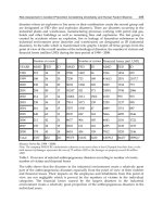
In the second case, the membrane permeance was extrapolated at different selective layer
thicknesses ranging between 2.5 and 100 micron. The results are reported in Figure 11, as
well as those obtained from literature review.
Obviously, the thickness of the separation layer greatly affects the membrane permeance
which resulted lowered from 2.12 x 10
-4
to 5.3 x 10
-6
at 350°C and from 7.85 x 10
-3
to 1.96 x 10
-
4
at 550°C by increasing the thickness of the separation layer from 2.5 to 100 micron. The
obtained results pointed out on the continuous industrial efforts aiming to develop
composite membrane made of a very thin Pd layer. It is worth nothing that reducing the
selective layer thickness allows membrane cost to be decreased (decreasing the Pd thickness
by a factor two reduces the total Pd cost by a factor four) and increasing the hydrogen flux,
which is in inverse proportion with the film thickness. On the other side, a too high decrease
in the selective film thickness may result in an excessive embrittlement of the membrane
which becomes too mechanically fragile for the condition of high temperature catalytic
processes.
0.0012 0.0013 0.0014 0.0015 0.0016 0.0017
1/T [1/°C]
-12
-10
-8
-6
-4
Ln(Permeance) [mol/m
2
s Pa
0.5
]
Shu et al., 1994
Souleimanova et al., 2002
This work
Jemaa et al., 1996
Kikuchi, 1995
Uemiya et al., 1990
Peters et al., 2008
Li and Rei, 2001
Cheng et al., 2002
Pizzi et al., 2008
Tong et al., 2005
Nair and Harold, 2008
Matsumura and Tong, 2008
Chen et al., 2010
Zahedi et al., 2009
Basile et al., 2005b
Chiappetta et al., 2010
Okazaki et al., 2009
2.5 micron
5 micron
10 micron
20 micron
50 micron
100 micron
Okazaki et al., 2011
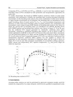
Fig. 11. Effect of membrane thickness on ECN membrane permeance
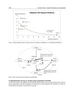
In terms of CH
4
conversion, the influence of the selective layer thickness is reported in
Figure 12, even at lower value than those reported in Figure 11.
At each operating temperature investigated, the decrease of membrane thickness resulted in
higher methane conversion. In particular, at 630°C, a reduction of membrane thickness from
2.5 micron to 0.5 micron may enhance methane conversion of 10% due to the higher
hydrogen removal. It is interesting to note that thickness thinner than 0.5 micron have no
more significant effect on the overall performance. Such a thickness could be considered as
Nuclear Power – Deployment, Operation and Sustainability
480
the technological limit to be overcome. Globally it is possible to reach CH
4
conversion
higher than 90% with a permeated H
2
flux of 300 Nm
3
/m
2
h bar
0.5
.
The achievement of this goal shows the industrial feasibility of this option up to now
demonstrated only on a laboratory scale, even if the last gap to be overcome for the
technology commercialization is represented by the optimization of membrane preparation
procedure with enhancement of their stability.
Fig. 12. Effect of membrane thickness on CH
4
conversion with ECN membrane
3.3 Application to nuclear power
In order to sustain the global endothermic steam reforming reaction, a part of the methane
feedstock must be burned in a fired heater. To reduce this consumption, purge gas coming
from PSA unit or retentate from the membrane separation unit have to be burned. The
calorific value of these streams is a function of composition and consequently of the
achieved conversion. A self-balance of heat exits with a fixed external natural gas supply, at
an appropriate level of feed conversion. Therefore, conversion should not exceed the point
closing the heat balance (around 60%).
Furthermore, it must be considered that owing to the high process temperature, the thermal
efficiency of this process is about 65 to 75%. Also, a substantial amount of greenhouse gases
(GHG) is emitted as CO
2
produced along with hydrogen. Moreover, carbon dioxide is also
emitted during the burning of a part of methane feedstock in order to sustain the global
endothermic balance of the steam reforming reaction. In total, a typical steam reforming
process emits up to 8.5 – 12 kg CO
2
per 1 kg H
2
. To prevent the emitted CO
2
to be released
into the atmosphere, it needs to be captured. Presently, all commercial CO
2
capture plants
use processes based on chemical absorption with amine solvents as monoethanolamine
(MEA) or (methyldiethanolamine) MDEA, which is a considerably energy intensive step
and thus is unfavourable to the overall process energy efficiency.
Therefore, a higher methane conversion is required to reduce the carbon dioxide emission
per unit of hydrogen produced. This could be achieved by using heat from an external
Reformer and Membrane Modules
(RMM) for Methane Conversion Powered by a Nuclear Reactor
481
source such as a high temperature nuclear reactor. Replacing the burning of natural gas by
nuclear heat allows avoiding, at least partially, all the CO
2
production related to fuel
burning (De Falco et al. accepted for publication, Iaquaniello and Salladini, 2011).
High temperature helium-cooled reactors are the best understood nuclear technology that
can supply high temperature heat for thermal processes for producing hydrogen. Nuclear
reactor designers became interested in high-temperature helium-cooled reactors more than
40 years ago because of the new possibility for heating the helium at the reactor exit up to
1000°C and the enhanced safety of the reactor (Mitenkov et al., 2004).
The synergistic production of hydrogen using fossil fuels and nuclear energy is considered
to be extremely advantageous, especially when performed through a recirculation-type
membrane reformer (Hori et al., 2005).
In particular, even assuming an idealistic case, in which all the heat generated by
combustion of hydrocarbon is used for the heat of endothermic reaction of steam reforming
as well as a portion of the heat released by exothermic water gas shift reaction, the
consumption of methane for the nuclear-heated steam reforming reaction is 17% less of that
of the conventional steam reforming reaction for producing the same amount of hydrogen.
In the actual case of conventional steam reforming as the heat utilization and the reaction
yield are limited, the efficiency of the process will be around 80%, that is 2.7 mol of
hydrogen produced from 1 mol of methane feed. In the case of nuclear-heated recirculation-
type membrane reformer, as no methane is consumed for combustion and the yield of
hydrogen is nearly stoichiometric, the nuclear-heated SMR reaction will produce 4 mol of
hydrogen from 1 mol of methane. Therefore, this process scheme will save about 30%
natural gas consumption, or reduce 30% carbon dioxide emission, comparing with
traditional process (Hori et al., 2005). Furthermore, typical merits of this process are: (i)
nuclear heat supply at medium temperature around 550°C, (ii) compact plant size and
membrane area for hydrogen production, (iii) efficient conversion of a feed fossil fuel, (iv)
appreciable reduction of carbon dioxide emission, (v) high purity hydrogen without any
additional process and (vi) ease of separating carbon dioxide for future sequestration
requirements.
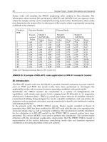
Figure 13 reports a plant configuration of hydrogen and pressurized CO
2
production
coupled with a nuclear reactor cooled by He.
Natural gas is compressed, heated and mixed with hydrogen recycle before entering the
hydro desulphurizer reactor (HDS). The desulphurised feed is mixed with steam, preheated
in the convective section CC-01 and fed to the first reforming step (R-01). The reformed gas
reaction mixture at 600-650°C is cooled down to a proper temperature for membrane
separation, i.e. 450-470°C, before entering the first separation module. Sweeping steam is
sent to the permeate side of the membrane to reduce the hydrogen partial pressure with a
consequent improvement of hydrogen permeation. The permeate side stream, composed of
hydrogen and sweeping steam, is sent to the cooling and water condensing section. The
retentate from the first membrane module is sent to the second reforming rector (R-02) for
further methane conversion.
A part of the final retentate is recycled to the post combustion chamber. The hydrogen
permeated is separated from water stream by condensation and routed to a compression
section and to a PSA unit where final purification is carried out. A portion of the H2
produced is recycled to the feed where it is needed to keep the catalyst in the first part of the
reformer in an active state.
Nuclear Power – Deployment, Operation and Sustainability
482
Fig. 13. Process scheme of hydrogen and pressurised CO
2
production coupled with a nuclear
reactor cooled by He
Thermal fluid used to transfer thermal energy from the nuclear cycle to reforming reactors is
CO
2
circulating within a closed loop. CO
2
is firstly heated up by the heat exchange medium
of a nuclear plant in an intermediate heat exchanger. Its temperature is further increased in
the post-combustion chamber where all the purge gas from the PSA unit together with a
portion of retentate are burned to achieve a correct temperature. Thus, the thermal fluid is a
pressurized mixture of only CO
2
and H
2
O due to the use of pure oxygen in post combustion.
After heat recovery, thermal fluid is cooled down to separate water from CO
2
. The latter is
recycled back to the nuclear reactor while a portion, corresponding to that produced in post
combustion, is removed from the closed loop. Water, produced in post combustion, can be
recycled to the process. This kind of separation is much simpler and less energy intensive
than a traditional physical absorption process with amine solutions. Moreover, providing
the reformer duty through pressurized carbon dioxide instead of, e.g., air allows to achieve
a higher heat transfer coefficient due to the higher heat capacity and gas emissivity.
By applying the proposed scheme, hydrogen and pressurized carbon dioxide are produced
with a nuclear heat source and with a reduced carbon dioxide emission. In this way, the
major portion of the heat required for the steam reforming reaction is not provided by the
combustion of fresh hydrocarbons but is supplied from a separate unit without carbon
dioxide emissions.
The scheme presented in Figure 13 realises a feed conversion of 90% with a carbon dioxide
production equal to 6 kgCO
2
/kgH
2
corresponding to 0.55 kgCO
2
/Nm
3
H
2
. From the energy
point of view, using a RMM architecture allows to produce hydrogen with a higher overall
energy efficiency. The reduced reforming temperature achievable only by membrane
application, allows performing the exothermic water gas shift reaction simultaneously with
the endothermic steam reforming reaction reducing in this way the net heat duty. The
proposed scheme achieves a hydrogen production with an overall energy efficiency of more
than 85%. Such a scheme could be also considered a first step in producing ammonia and
urea by reacting ammonia with CO
2
recovered (Figure 14).
Reformer and Membrane Modules
(RMM) for Methane Conversion Powered by a Nuclear Reactor
483
Fig. 14. Process scheme for urea production coupling a membrane steam reformer with a
nuclear reactor
4. Economic analysis
An economic analysis was performed at first focusing attention on membrane production
costs, further the analysis was extended to the coupled process scheme proposed in the
previous section.
In order to tackle this issue and to be able to forecast a production cost for thin Pd-based
membranes, it is important to introduce the concept of ‘‘economics of learning’’ in
understanding the behaviour of all added costs of membranes as cumulative production
volume increased. Such economics of learning or law of the experience may be expressed
more precisely in an algebraic form (7):
c
n
= c
1
n
-a
(7)
where c
1
is the cost of the unit production (square meter of membrane for instance), c
n
is the
cost of the n
th
unit of production, n is the cumulative volume of production, and a is the
elasticity of cost with regard to output.
Graphically, the experience curve is characterized by a progressively declining gradient,
which, when translated into logarithms, is linear. The size of experience effect is measured
by the proportion by which costs are reduced with subsequent doublings of aggregate
production.
Constructing an experience curve is a simple matter once the data are available. Of course
for the Pd-based or ceramic membrane such dates are limited to minimal surface (less than 1
m
2
), which can, however, be used as starting point of the curve. The other issue associated
with drawing an experience curve is that cost and production data must be related to a
‘‘standard product’’, which is not the case due to the fact that in the membrane technology
no standard is yet emerged and there is a lot of discussion on the membrane composition
and preparation method, supporting matrix and other mechanical and construction details.
It is, however, a fact that costs decline systematically with increases in cumulative output.
The assumptions made in the following are that c
1
=50,000 € and a=0.25, where c
1
value
derived by Tecnimont-KT recent experience in building a pilot unit, meanwhile the ‘‘a’’
factor was assumed as average value typically between 20 and 30%.
Using such a data is possible to forecast the cost for m
2
of membrane module versus the
cumulative value of production, expressed in terms of m
2
. Table 4 shows such data.
Nuclear Power – Deployment, Operation and Sustainability
484
Cumulated production m
2
€ cost per m
2
1,000 8,900
10,000 5,000
100,000 2,800
1,000,000 1,600
10,000,000 900
Table 4. Cost per m
2
of membrane module versus cumulated production
From the drawn experience curve, some implications for the membranes market business
strategy can be extracted. The first and more important question to answer is when a
1,000,000 m
2
of membrane module cumulative production could be reached in order to have
a unit cost around 1.600 € per m
2
of membrane.
In order to answer such a question, further considerations need to be developed, to relate
surface to membrane module to the H
2
production and to the introduction of such a new
technology in the market.
On previous published data, Iaquaniello et al. (2008) were calculating for a open membrane
reactor architecture a surface of 1,000 m
2
for an installed capacity of 10,000 Nm
3
/h of
hydrogen. The envisaged installed capacity in the hydrogen market is today around 1 MM
Nm
3
/h of capacity per year, which translated into a production of 100,000 m
2
of membrane
year, once the new technology will supersede the conventional one.
To derive the rate of membranes technology introduction in the market a Volterra equation
was considered (8):
x = A/(1+e
(Bx)
)+ C (8)
where A, B, C are constants and x is the cumulative production.
Such equation, also called ‘‘S logistic curve’’ is used to describe a process with a low growth
which accelerate with time to seem an exponential growth. A 10-year period (2012–2022) is
considered to achieve 50% substitution in the conventional market starting from 2012, which
roughly implies that over the next decade half a million of square meters of membranes
modules could be produced. With such cumulative production around year 2020, the
membrane cost per m
2
could reach the target of 1.600 € per m
2
and the overall market will
have a size of 1 billion of € per year.
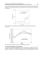
Figure 14 represents the cumulative production coupled to the ‘‘S’’ curve.
The approach used to determine the growth of the membranes market, together with the
cumulative production does not, however, identify the real factors that determine its
dynamics. As matter of fact, the experience curve combines four sources of costs reduction:
learning, economics of scale, process innovation, and improved production design.
Economics of scale, conventionally associated with manufacturing operations, is probably
the most important of these costs drivers and exists wherever as the scale of production
increases unit costs fall. A plant capacity has then an economic sense if a minimum
efficiency plant capacity is reached.
This will imply that to reach the required reduction in the membrane cost, not only a few
specialized technologies must emerge, but the production market will be concentrated in
few highly specialized production plants.
Regarding the proposed process scheme coupling a membrane based steam reformer with a
nuclear reactor, a preliminary investigation was carried out under the basic assumption that
the cost of electric power from nuclear source is 0.03€/kWh (Romanello et al., 2006). Thus, in
Reformer and Membrane Modules
(RMM) for Methane Conversion Powered by a Nuclear Reactor
485
order to produce 1000 kWh
e
the total costs amount is 30€. Considering an efficiency equal to
around 34%, so that 3000 kWh
th
(or 2580000 kcal) should be produced to obtain our power
target, this will translate into a cost of 12€/MMkcal against more than 30€ for heat produced
from natural gas. The variable costs of producing H
2
are then reduced of more than 20%
without considering the beneficial effects of reduced CO
2
emissions in the atmosphere.
Fig. 15. Cumulative production coupled to the “S” curve
Compared to the thermochemical processes, hydrogen production by nuclear-heated steam
reforming of natural gas is considered to be much closer to commercialization and is viewed
as an intermediate step to nuclear-driven hydrogen production from water.
Alternatively such process could be modified to produce urea without any additional CO
2
emissions.
5. Conclusions and future perspectives
Membrane reforming with recirculation of reaction products in closed loop configuration is
a particularly promising nuclear application, even if one of the last gap to be overcome for
the technology commercialization of membrane reformers is represented by the
optimization of membrane preparation procedure with enhancement of their stability.
Because the nuclear heat is needed at below 600°C, it employs a compact membrane and
reformer, and gives efficient conversion of the hydrocarbon feed and high-purity hydrogen
without additional processing. With all these benefits, the synergistic blending of fossil fuels
and nuclear energy to produce hydrogen, ammonia and urea, can be an effective solution
for the world until large-scale thermochemical water splitting processes, which may benefits
from economy of scale, are available. For both the fossil fuels industry and the nuclear
industry, this approach offers a viable symbiotic strategy with the minimum of impact on
resources, the environment and the economy.
6. Acknowledgment
The pre-industrial natural gas steam reforming RMM plant was developed within the
framework of the project “Pure hydrogen from natural gas reforming up to total conversion
obtained by integrating chemical reaction and membrane separation”, financially supported by
Nuclear Power – Deployment, Operation and Sustainability
486
MIUR ( FISR DM 17/12/2002)-Italy. The authors are grateful to Prof. Luigi Marrelli and
Prof. Diego Barba for their support.
7. References
Basile, A.; Gallucci, F. & Paturzo, L. (2005a). A dense Pd/Ag membrane reactor for methanol
steam reforming: Experimental study. Catalysis Today, Vol. 104, No. 2-4, (June 2005),
pp. 244-250, ISSN 0920-5861.
Basile, A.; Gallucci, F. & Paturzo, L. (2005b). Hydrogen production from methanol by
oxidative steam reforming carried out in a membrane reactor. Catalysis Today, Vol.
104, No. 2-4, (June 2005), pp. 251-259, ISSN 0920-5861.
Chen, W. ; Hu, X. ; Wang, R. & Huang, Y. (2010). On the assembling of Pd/ceramic
composite membranes for hydrogen separation. Separation and Purification
Technology Vol. 72, No. 1, (March 2010), pp. 92-97, ISSN 1383-5866.
Cheng, Y.S.; Pena, M. ; A., Fierro J. L. ; Hui, D.C.W. & Yeung, K.L. (2002). Performance of
alumina, zeolite, palladium, Pd-Ag alloy membranes for hydrogen separation from
towngas mixture. Journal of Membrane Science, Vol. 204, No. 1-2, (July 2002), pp. 329-
340, ISSN 0376-7388.
Chiappetta, G.; Barbieri, G. & Drioli, E. (2010). Pd/Ag based membranes reactors on small
scale: assessment of the feed pressure and design parameters effect on the
performance. Chemical Engineering and Processing: Process Intensification, Vol. 49, No.
7, (July 2010), pp. 722-731, ISSN 0255-2701.
Ciambelli, P.; Palma, V.; Palo, E.; Iaquaniello, G.; Mangiapane, A. & Cavallero, P. (2007).
Energy sustainable development through methane autothermal reforming for
hydrogen production. AIDIC Conference Series, Vol. 8, pp. 67-76, ISBN 0390-2358.
De Falco, M. ; Di Paola, L. ; Marrelli, L. & Nardella, P. (2007). Simulation of large-scale
membrane reformers by a two-dimensional model. Chemical Engineering Journal,
Vol. 128, No. 2-3, (April 2007), pp. 115-125, ISSN 1385-8947.
De Falco, M. ; Iaquaniello, G. & Salladini, A. (2011a). Experimental tests on steam reforming
of natural gas in a reformer and membrane modules (RMM) plant. Journal of
Membrane Science, Vol. 368, No. 1-2, (February 2011), pp. 264 – 274, ISSN 0376-7388.
De Falco, M. ; Marrelli, L. & Iaquaniello, G. (2011b). Membrane Reactors for Hydrogen
Production Processes. Springer Ed., ISBN 978-0-85729-150-9.
De Falco, M. ; Salladini, A. & Iaquaniello, G. (accepted for publication). Reformer and
membrane modules (RMM) for methane conversion : experimental assessment and
perspectives of said innovative architecture. ChemSusChem, ISSN 1864-564X.
Dittmeyer, R. ; Höllein, V. & Daub, K. (2001). Membrane reactors for hydrogenation and
dehydrogenation processes based on supported palladium. Journal of Molecular
Catalysis A: Chemical, Vol. 173, No. 1-2, (September 2001), pp. 135–184, ISSN 1381-
1169.
Dybkjaer, I. (1995). Tubular reforming and autothermal reforming of natural gas – an
overview of available processes. Fuel Processing Technology, Vol. 42, No. 2-3, (April
1995), pp. 85-107, ISSN 0378-3820.
Faur Ghenciu, A. (2002). Review of fuel processing catalysts for hydrogen production in
PEM fuel cell systems. Current Opinion in Solid State & Materials Science, Vol. 6, No.
5, (October 2002), pp. 389-399, ISSN 1359-0286.
Reformer and Membrane Modules
(RMM) for Methane Conversion Powered by a Nuclear Reactor
487
Hori, M.; Matsui, K.; Tashimo, M.; Yasuda, I. (2005). Synergistic hydrogen production by
nuclear-heated steam reforming of fossil fuels. Progress in Nuclear Energy, Vol. 47,
No. 1-4, (December 2005), pp. 519-526, ISSN 0149-1970.
Iaquaniello, G.; Giacobbe, F.; Morico, B.; Cosenza, S.; Farace, A. (2008). Membrane reforming
in converting natural gas to hydrogen : Production costs, Part II. International
Journal of Hydrogen Energy, Vol. 33, No. 22, (November 2008), pp. 6595-6601, ISSN
0360-3199.
Iaquaniello, G. & Salladini, A. (2011). Method for hydrogen production. European Patent
Application EP11150491.
Jemaa, N. ; Shu, J. ; Kaliaguine, S. & Grandjean, B. (1996). Thin palladium film formation on
shot peening modified porous stainless steel substrates. Industrial & Engineering
Chemistry Research, Vol. 35, No. 3, (March 1996), pp. 973-977, ISSN 0888-5885.
Kikuchi, E. (1995). Palladium/ceramic membranes for selective hydrogen permeation and
their application to membrane reactor. Catalysis Today, Vol. 25, No. 3-4, (August
1995), pp. 333-337, ISSN 0920-5861.
Li, Y.M. & Rei, M.H. (2001). Separation of hydrogen from the gas mixture out of catalytic
reformer by using supported palladium membrane. Separation and Purification
Technology, Vol. 25, No. 1-3, (October 2001), pp. 87-95, ISSN 1383-5866.
Matsumura, Y. & Tong, J. (2008). Methane steam reforming in hydrogen-permeable
membrane reactor for pure hydrogen production. Topics in Catalysis, Vol. 51, No. 1-
4, (October 2008), pp. 123-132, ISSN 1022-5528.
Mendes, D. ; Mendes, A. ; Madeira, L. M. ; Iulianelli, A. ; Sousa, J. M. & Basile, A. (2010). The
Water-Gas Shift Reaction: From Conventional Catalytic Systems to Pd-based
Membrane Reactors – a Review. Asian-Pacific Journal of Chemical Engineering on
Membrane Reactors, Vol. 5, No. 1, (August 2009), pp. 111-137, ISSN 1932-2143.
Mitenkov, F.M. ; Kodochigov, N.G. ; Vasyaev, A.V. ; Golovko, V.F. ; Ponomarev-Stepnoi,
N.N. ; Kukharkin, N.E. & Stolyarevskii, A.Ya. (2004). High-temperature gas-cooled
reactors-energy source for industrial production of hydrogen. Atomic Energy, Vol.
97, No. 6, (December 2004), pp. 829-840, ISSN 1063-4258.
Mulder, M. (1996). Basic Principles of Membrane Technology. Kluwer Academic: Dordrecht
pp. 564.
Nair, B. K. R & Harold, M. P. (2008). Experiments and modeling of transport in composite
Pd and Pd/Ag coated alumina hollow fibers. Journal of Membrane Science, Vol. 311,
No. 1-2, pp. 53-67, ISSN 0376-7388.
Ockwig, N.W. & Nenoff T.M. (2007). Membranes for hydrogen separation. Chemical Reviews,
Vol. 107, No. 10, (October 2007), pp. 4078-4140, ISSN 0009-2665.
Okazaki, J. ; Ikeda, T. ; Pacheco Tanaka, D.A. & Sato, K. (2011). An investigation of thermal
stability of thin palladium-silver alloy membranes for high temperature hydrogen
separation. Journal of Membrane Science, Vol. 366, No. 1-2, pp. 212-219, ISSN 0376-
7388.
Okazaki, J. ; Ikeda, T. ; Pacheco Tanaka, D. A. ; Suzuki, T. M. & Mizukami F. (2009). In situ
high-temperature X-ray diffraction study of thin palladium-α-alumina composite
membranes and their hydrogen permeation properties. Journal of Membrane Science,
Vol. 335, No. 1-2, pp. 126-132, ISSN 0376-7388.
Palo, E. (2007
). Structured catalysts for hydrogen production by methane autothermal
reforming. PhD Thesis, University of Salerno.
Nuclear Power – Deployment, Operation and Sustainability
488
Peters, T. A.; Stange, M.; Klette, H. & Bredesen R. (2008). High pressure performance of thin
Pd-23%Ag/stainless steel composite membranes in water gas shift gas mixture:
influence of dilution, mass transfer and surface effects on hydrogen flux. Journal of
Membrane Science, Vol. 316, No. 1-2, pp. 119-127, ISSN 0376-7388.
Pizzi, D.; Worth, R. ; Baschetti, M. G. ; Sarti G. C. & Noda K. (2008). Hydrogen permeability
of 2.5 μm palladium-silver membranes deposited on ceramic supports. Journal of
Membrane Science, Vol. 325, No. 1, pp. 446-453, ISSN 0376-7388.
Romanello, V.; Lomonaco, G. ; Cerullo, N. (2006). I veri costi dell’energia nucleare.
NT1127(2006). Università di Pisa.
Sanchez Marcano, J.G. & Tsotsis, T.T. (2002). Catalytic membranes and membrane reactors.
Wiley-VCH Verlag, Weinheim.
Shu, J.; Grandjean, B. & Kaliaguine, S. (1994). Methane steam reforming in asymmetric Pd-
and Pd-Ag/porous SS membrane reactors. Applied Catalysis A : General, Vol. 119,
No. 2, (November 1994), pp. 305-325, ISSN 0926-860X.
Souleimanova, R.S. ; Mukastan, A.S. & Varma, A. (2002). Pd membranes formed by
electroless plating with osmosis: H
2
permeation studies. AIChE Journal, Vol. 48, No.
2, (February 2002), pp. 262-268, ISSN 1547-5905.
Tong, J.; Matsumura, Y. ; Suda, H. & Haraya, K. (2005). Thin and dense Pd/CeO
2
/MPSS
composite membrane for hydrogen separation and steam reforming of methane.
Separation and Purification Technology, Vol. 46, No. 1-2, (November 2005), pp. 1-10,
ISSN 1383-5866.
Uemiya, S.; Sato, N.; Ando, H. ; Matsuda, T. & Kikuchi, E. (1990). Steam reforming of
methane in a hydrogen-permeable membrane reactor. Applied Catalysis, Vol. 67, pp.
223-230.
Xia, Y.; Lu, Y.; Kamata, K.; Gates, B. & Yin, Y. (2003). Macroporous materials containing
three-dimensionally periodic structures. Chemistry of Nanostructured Materials
(Ed.: Yang, P.), World Scientific 69-100.
Zahedi, M.; Afra, B.; Dehghani-Mobarake, M. & Bahmani, M. (2009). Preparation of a Pd
membrane on a WO
3
modified Porouys Stailess steel for hydrogen separation.
Journal of Membrane Science, Vol. 333, No. 1-2, (May 2009), pp. 45-49, ISSN 0376-
7388.
20
Hydrogen Output from Catalyzed
Radiolysis of Water
Alexandru Cecal and Doina Humelnicu
“Al.I. Cuza” University, Department of Chemistry, Iasi,
Romania
1. Introduction
Energy is the source of the vitality of industrial civilization and a necessary condition to
save the world from poverty.
Current methods of generating energy for the industrial civilization undermine local,
regional, global environmental conditions, and are based mainly on the processing of fossil
resources.
Nowadays, the dawn of a new renewable energy revolution is occurring. It is the use of
hydrogen instead of using oil and its derivatives. The stakes are global. The fight against the
greenhouse effect requires finding a solution for the production of green energy.
The relatively new method of producing electricity is based on conversion, in fuel cells, of
heat and energy of certain chemical substances, in electricity.
Since fuel cells convert fuel directly in electricity two to three times more efficiently than the
thermodynamic conversion, the fuel cell is, by definition, a very efficient technology and,
being a potential source of high energy still, clean and, compatible with renewable energy
policy, reliable and sustainable over time (does not contain moving parts).
Hydrogen is the key to the future of energy having the highest energy content per unit
weight of all known fossil. When burned in an engine, hydrogen produces zero issues; when
the power source in a fuel cell, clean waters it is the only residue at 250-300 ºC (International
Atomic Energy Agency, [IAEA], 1999; Ohta&Veziroglu, 2006; Veziroglu, 2000). Combined
with other technologies, such as carbon capture and storage, renewable energies, fusion
energy, it is possible that the fuel cell will generate in future energies without harmful
programs. Hydrogen is the only energy carrier making it possible to drive an aircraft using
solar energy.
At the beginning of the XXIst century it is assumed that fuel cells will become a pervasive
technology; hydrogen as fuel is becoming increasingly presented as the "solution", also by
carmakers, ecologists, and governments who do not want to impose unpopular measures to
limit car traffic.
The use of hydrogen will extend from cell phones to electric power plants.
Implementing the "hydrogen economy" will lead to changes not seen in the XIX century and
early XX century when the world went through the experience of the last energy revolution.
Environmentalists argue that there is no alternative to a hydrogen based energy system
because the reserves of exploitable oil and natural gas, indispensable resource materials not
Nuclear Power – Deployment, Operation and Sustainability
490
only in energy industry, but also in petrochemicals (holds might miss today plastics), will be
completely exhausted in less than a century.
T. N. Veziroglu summarizes some properties that recommend the use of hydrogen as energy
carrier produced from unconventional technologies, because hydrogen is a concentrate
(energy) sources of primary energy, presented to the consumer in a convenient form, having
a relatively cheap production cost as a result of technological refinements. Moreover
hydrogen has a high efficiency of converting in various forms of energy and represents an
inexhaustible source, considering that it is obtained from water, and by use it becomes
water.
Hydrogen production and consumption is a closed cycle, that maintains constant power
production – water, and represent a classic cycle of raw material recycling – it is the easiest
and cleanest fuel. Burning hydrogen is almost without polluting emissions, excepting NO
x
,
which can also be removed by proper adjustment of combustion conditions. It has a
gravimetric "energy density" higher than any other fuel.
Hydrogen can be stored in several ways: gas at normal pressure or high pressure, as liquid
or solid form of hydrides and can be transported long distances in any one of the above
mentioned forms.
Assessing the effects of global economic shift to energetic system based on hydrogen it can
be established that environmental pollution through energy production will not be a
problem and hydrogen economy will lead to industrial transformations comparable to those
produced in the microelectronics industry;
Moreover economic resources, financial, intellectual, intended for energy today and
environmental and ecological problems, will be geared towards solving, for the good of
mankind, other productive tasks. Life will get better. The literature state that the idea of a
"hydrogen economy" would have been born and developed under the impact of oil shock,
using hydrogen as fuel being presented as the last cry of modernity. In fact, however, using
hydrogen as a "universal fuel" devoid of pollutant emissions appeared long before the oil
shock in 1973.
The literature state that the idea of a "hydrogen economy" would have been born and
developed under the impact of oil shock, using hydrogen as fuel being presented as the last
cry of modernity. In fact, however, using hydrogen as a "universal fuel" devoid of pollutant
emissions appeared long before the oil shock in 1973.
2. Hydrogen production using the heat resulted in nuclear reactors after
splitting the U-235 or Pu-239 nuclei
A series of tests are known to produce hydrogen by water splitting by making calls to the
thermochemical cycles (hybrid) initiated by heat inside the reactor cores from fission of U-
235, Pu-239, etc. (Besenbuch et al. 2000; Rahier et al., 2000; Tashimo et al., 2003, Verfondern,
2007)
An outline of such a plant for water decomposition through cycles of thermochemical
reactions initiated by heat from inside a nuclear reactor is presented below:
To this end it used a series of thermochemical cycles or hybrid cycles that have been
developed in different types of specialized research institutes or companies with business in
areas of nuclear energy: General Atomics (USA) JAEA, Julich JRC, NRC -Ispra and other
units from France, China, South Korea, Russia etc.
Hydrogen Output by Means of Catalysed
Radiolysis of Water Using as Irradiation Source the Spent Nuclear Fuel Elements
491
Nuclear reactor
High temperature
gas
Water spliting
Steam turbine
Electric
generator
H
2
output
a. Sulfur-iodine cycle is shown by the sequence of reactions that occur at different
temperatures:
(9I
2
)
l
+ (SO
2
)
g
+ (16H
2
O)
l
120 C
(2HI + 10H
2
O + 8I
2
)
l
+ (H
2
SO
4
+ 4H
2
O)
l
(2HI + 10H
2
O + 8I
2
)
l
230 C
(2HI)
g
+ (10H
2
O + 8I
2
)
l
(2HI)
g
330 C
H
2
+ (I
2
)
g
(H
2
SO
4
+ 4H
2
O)
l
330 C
(H
2
SO
4
)
l
+ (4H
2
O)
l
(H
2
SO
4
)
l
360 C
(H
2
SO
4
)
g
(H
2
SO
4
)
g
400 C
(SO
3
)
g
+ (H
2
O)
g
(SO
3
)
g
870 C
(SO
2
)
g
+1/2O
2
At first, through the Bunsen reaction, there result two-phase nemiscible acids: HI and
H
2
SO
4
.
These oxides, under the influence of high temperature, will decompose releasing hydrogen
(and oxygen), and I
2
and SO
2
, which will restore (as reactants) the Bunsen reaction.
b. Westinghouse cycle takes place through two reactions, due to sulfuric acid:
(H
2
SO
4
)
g
850 C
(SO
2
)
g
+ (H
2
O)
l
+ 1/2O
2
(SO
2
)
g
+ (2H
2
O)
l
100 C
(H
2
SO
4
)
l
+ H
2
The second reaction takes place in an electrolytic cell at low temperature when there result
hydrogen and sulfuric acid in the aqueous phase at a potential of 0.17 V and at a pressure of
about 1 MPa. Then the cycle is repeated with gaseous H
2
SO
4
.
c. UT-3 cycle, developed in Japan, is represented by the following reactions:
CaBr
2
+ H
2
O
750 C
CaO + 2HBr
CaO + Br
2
600 C
CaBr
2
+ 1/2O
2
Fe
3
O
4
+ 8HBr
300 C
3FeBr
2
+ 4H
2
O + Br
2
Nuclear Power – Deployment, Operation and Sustainability
492
3FeBr
2
+ 4H
2
O
600 C
Fe
3
O
4
+ 6HBr + H
2
on the account of salts or metal oxides in solid form, as "spherical pellets”. Due to the CaBr
2
high melting point, the efficiency of the hydrogen production process is of only 40%.
(H
2
SO
4
)
g
700 1000 C
(H
2
O)
g
+ (SO
3
)
g
(SO
3
)
g
700 1000 C
(SO
2
)
g
+ 1/2O
2
(SO
2
)
g
+ (Br
2
)
l
+(2H
2
O)
l
100 C
(2HBr)
g
+ (H
2
SO
4
)
l
(2HBr)
l
200 C
H
2
+ Br
2
d. The Mark-13 or the cycle of H
2
SO
4
- Br
2
, is described by the following chemical
transformations:
(H
2
SO
4
)
g
700 1000 C
(H
2
O)
g
+ (SO
3
)
g
(SO
3
)
g
700 1000 C
(SO
2
)
g
+ 1/2O
2
(SO
2
)
g
+ (Br
2
)
l
+(2H
2
O)
l
100 C
(2HBr)
g
+ (H
2
SO
4
)
l
(2HBr)
l
200 C
H
2
+ Br
2
Here hydrogen is released by decomposing electrolytic HBr, with an efficiency of 37 %.
e. Metal-metal oxide cycle developed at PSI, Switzerland, schematically as follows:
M
m
O
n
→ M
m
O
n-x
+ x/2O
2
M
m
O
n-x
+ xH
2
O → M
m
O
n
+ xH
2
If water splitting occurs at 650 ºC, the reduction of the metal oxide is at a temperature of
2000 ° C. The research was done on the system: Fe
3
O
4
/FeO; Mn
3
O
4
/MnO, ZnO / Zn;
Co
2
O
3
/CoO or MFe
2
O4, where M = Cu, Ni, Co, Mg, Zn.
f. Thermochemical cycle methane- methanol - iodomethane was tested in South Korea and can
be played as follows:
CH
4
+ H
2
O CO + 3H
2
CO + 2H
2
CH
3
OH
2CH
3
OH + I
2
2CH
3
I + H
2
O + 1/2O
2
2CH
3
I + H
2
O CH
3
OH + CH
4
+ I
2
Transformations occur at 150 °C and a pressure of 1.2 MPa.
There are also known other hydrogen production processes based on thermochemical
cycles, such as another one, HHLT and others.
Hydrogen Output by Means of Catalysed
Radiolysis of Water Using as Irradiation Source the Spent Nuclear Fuel Elements
493
g. High-temperature electrolysis. Hydrogen can be produced by electrolysis of water vapor
at 750-950 ° C, by the reactions:
K(-): 2H
2
O + 4e
-
→ 2H
2
+ 2O
2-
A(+): 2O
2-
→ O
2
+ 4e
-
3. Radiolytic split of water molecules in several experimental conditions
In this sense, it know a number of studies respecting the hydrogen obtaining by catalyzed
decomposition of water under the influence of nuclear radiation emitted by some sources,
including fission products recovered from spent nuclear fuel.
Thus, Maeda and co-workers have studied obtaining of molecular hydrogen by irradiation
with γ radiations of silicagels and metal oxides dispersed in water.
They found that a higher radiolytic yield was obtained in the silicagels case with pore
diameter of about 2 nm, and the most active area against water decomposition under the
action of γ radiation was the SiO
2
dried at 100 ºC (Maeda et al., 2005).
Yamamoto and collab. have used in their investigations nanoparticles of TiO
2
and α- and β-
Al
2
O
3
noting that the radiolytic yield of molecular hydrogen production when irradiated
with γ radiation of aqueous solutions with α- and β- Al
2
O
3
is 7-8 times higher than water
irradiation without catalyst (Yamamoto et al., 1999)
Jung and collab. studied the effect of adding EDTA on the reaction of water radiolysis
containing TiO
2
and noted that the presence of this organic compound increased the
radiolytic yield of molecular hydrogen (Jung et al.,2003).
Rotureau and collab. studied the obtaining molecular hydrogen from water radiolysis in
presence of SiO
2
and of mesoporous molecular sieves obtaining a value of radiolytic yield of
molecular hydrogen
H
2
G = 3 (Rotureau et al. 2006).
Recently, Kazimi and Yildiz studied the obtaining of hydrogen through alternative
nuclear energy, including radioactive wastes that result from nuclear plants (Yildiz &
Kazimi, 2006).
Brewer and colleagues have used complex supramolecular of ruthenium and rhodium in the
study of water decomposition under the action of radiant energy (Brewer & Elvington,
2006).
Masaki and Nakashima studied the gamma-irradiation of Y zeolites both in form Na (NaY)
and form H (HY). Discussions on obtaining H and H
2
were based on comparing values
H
2
G
and G
H
between systems NaY- and HY-water. They obtained higher values of radiolyitc yield
of H
2
due to energy transfer from zeolite to absorbed water (Nakashima & Masaki, 1996).
The G(H
2
) values of HY system were 3 times higher than those of system NaY.
Seino and co-workers observed that the nanoparticles of TiO
2
and Al
2
O
3
dispersed in water
would lead to a significant increase of radiolytic yields of hydrogen to radiolytic yield of
pure water. They also noted that radiolytic yield of hydrogen depends on gamma radiation
dose absorbed and metal oxide particle size (Seino et al., 2001; Seino et al., 2001).
Yoshida and collab. proposed to get hydrogen by gamma irradiation of water in the
presence of Al
2
O
3
particles of different diameters. The maximum amount of hydrogen
produced was 3.48 µmol/cm
3
for water containing Al
2
O
3
particles with diameter of 3 µm,
value three times higher than the one obtained for the systems with pure water (Yoshida et
Nuclear Power – Deployment, Operation and Sustainability
494
al., 2007). Hydrogen produced from catalyzed reactions of water radiolysis was determined
by gas chromatography.
Cecal and others (intended to obtain hydrogen through water radiolysis in the presence of
solid catalysts, in different experimental conditions, under the action of gamma rays emitted
by a source of Co
60
. The produced hydrogen was determined by a device specially adapted
for mass spectrometer (Cecal et al., 2001; Cecal et al., 2003; Cecal et al., 2004). This study may
be accomplished using as irradiation γ source so called spent nuclear fuel elements extracted
from nuclear plants as high level radioactive wastes, instead of the β-γ Co-60 or Cs-137
radionuclides.
4. Irradiation characteristics
Qualitative and quantitative effects of phenomena suffered by substances after interaction
with ionizing radiation are determined by the characteristics of the irradiation process.
Irradiation process is characterized by the following quantities (Arnikor, 1987; Ferradini &
Pucheault, 1983):
- radiation intensity,
- absorbed dose,
- absorbed dose rate,
- dose equivalent,
- linear energy transfer radiation (LET).
Radiation intensity: This feature expresses the amount of energy emitted by source, and
expressed in J/s.
Absorbed dose, denoted D
a
, represents the amount of energy transferred by incident radiation
to unit mass of matter, energy absorbed by matter, respectively. In I.S absorbed dose is
expressed as Gray (Gy):
1 Gy = 1 J/kg = 6, 24·10
13
eVg
-1
.
Absorbed dose rate represents the energy received by the unit of mass per unit time. It is
usually expressed in Gy/s, but there are also used kGy/h, Mgy/h, as well as rad/s,
rad/min, rad/day if necessary.
Equivalent dose represents the radiation effect on the organism. Even at the same absorbed
dose biological effects on living organisms may be different. This differential action is
quantified by introducing a quality factor of incident radiation. As unit of measurement in
I.S. there is used Sievert (Sv), which is defined as equivalent dose to the body (tissue)
exposed to radiations with quality factor equal with unit when absorbed dose is 1 Gy.
1 Sv = ν x 1 Gy, where:
ν – coefficient which depends on radiation quality, for X or γ, ν= 1.
Linear energy transfer radiation (LET)
As a result of interaction with matter, electromagnetic radiations continuously lose energy,
photon beam intensity gradually decreasing as they penetrate matter. The phenomenon is
called linear energy transfer noted LET, and it is expressed quantitatively by the radiation
energy loss per unit length, LET = -dE/dx, with the unit keV/μm.
Linear energy transfer should increase as the particle slows down towards the end of the
journey so that much of the ionization and excitation produced by fast electrons is produced
on the path of gamma radiation, where linear energy transfer value is much higher than
average.
Hydrogen Output by Means of Catalysed
Radiolysis of Water Using as Irradiation Source the Spent Nuclear Fuel Elements
495
With the linear energy transfer there can be characterized, by a number the „quality” of a
radiation, not always describing the type of radiation and its energy.
5. Water radiolysis
5.1 General considerations
A permanent presence of water and ionizing radiation in nature, show the appearance of
water radiolysis on Earth and outside it. Laboratory experiments and computer simulations
of the processes induced by radiolysis relate to radioactive action of
40
K in the ocean 3800
Ma (1 Ma= 1 000 000 years ago) and natural radiation from the groundwater nuclear reactor
of the Earth in its infancy.
Radiation-induced decomposition of water molecules, water radiolysis, is carefully studied
for several authors, as Debiern, Marie Sklodowska Curie, O. Fricke, J. Franck, J. Weiss, Hart,
Boag using different experimental conditions.
5.2 Mechanism of water radiolysis
As a result of water radiolysis with a beam of high-energy radiation as γ radiation or an
accelerated electron beam, it occurs excitation and ionization of water molecules,
phenomenon that leads to the formation of various ion species, radicals and new
molecules – radical theory of water radiolysis (Belloni &Mostafavi, 2001; Kiefer, 1989;
Majer, 1982).
According radicals’ theory, radiolysis of water flows in three distinct phases:
a. Physical stage
A few pico-seconds after irradiation it is discovered the occurrence of excited molecules,
H
2
O* and ionized H
2
O
+
as of secondary electrons with high kinetic energy:
H
2
O
e,
H
2
O* (1.1)
H
2
O * → H
2
O+ (1.2)
Secondary electrons, Compton or photoelectric are fast slowed down and thermalised, after
which they are promptly captured by water molecules, hydrating themselves, (e
aq
-
).
Highlighting the hydrated electron is of great importance in the development of radiation
chemistry. Electron hydration corresponds to the stabilization phase through dipole of
solvent molecules:
e- + H
2
O → e
aq
- (1.3)
e- + H
2
O → H. + OH- (1.4)
At physico-chemical stage, which takes about 10
-13
s, absorbed energy is redistributed through
interactions with other stable or excited molecules and ions by splitting olyatomic molecules
or through ion-molecule reactions.
It is noticeable that ion-molecule reactions do not necessarily imply ionized molecule
movement; interactions can take place in liquid and at a distance of order of several
interatomic distances:
H
2
O* → H. + .OH (1.5)
Nuclear Power – Deployment, Operation and Sustainability
496
H
2
O+ + H
2
O → H
3
O+ + OH (1.6)
Ionized molecule can be neutralized by an electron:
H
3
O+ + e- → H
3
O (1.7)
which quickly dissociates:
H
3
O → H
2
O + H. (1.8)
H
3
O → e- + H
3
O+ (1.9)
Formed radicals can combine with each other, forming molecules:
H. + H. → H
2
(1.10)
.OH + .OH → H
2
O
2
(1.11)
.OH + H. → H
2
O. (1.12)
Chemical stage, which takes about 10
-10
s is the phase in which there occur reactions between
species formed in previous steps: recombination between radicals, ions, molecules and free
electrons:
.OH + H
2
→ H
2
O + H. reaction that inhibits radiolytic decomposition water (1.13)
H. + H
2
O
2
→ H
2
O + OH. (1.14)
e- + H
2
O
2
→ .OH + HO- (1.15)
HO
2
. + H. → H
2
O
2
(1.16)
reaction which allows to explain the increase concentration of H
2
O
2
.
Molecular oxygen is produced through the following reactions:
OH + H
2
O
2
→ HO
2
. + H
2
O (1.17)
HO
2
. + HO
2
. → H
2
O
2
+ O
2
(1.18)
In the presence of dissolved molecular oxygen reaction takes place:
O
2
+ H. → HO
2
. (1.19)
Hydrated electron e
aq
-
has both properties:
- reducing: e- + H
2
O → H + HO- (1.20)
- and basic: e- + H+ → H. (1.21)
Therefore, a few nano-seconds after irradiation, in water there are present the following
species ionics, radicalics and molecules:
H
3
O
+
, HO
-
, H
.
,
.
OH, HO
2
.
, H
2
, O
2
, H
2
O
2
, of which the following are stable: H
2
, H
2
O
2
, H
3
O
+
,
and short-lived free radicals e
aq
-
, H
.
,
.
OH, HO
2
.
.
Hydrogen Output by Means of Catalysed
Radiolysis of Water Using as Irradiation Source the Spent Nuclear Fuel Elements
497
5.3 Physical and chemical properties of primary species formed in water radiolysis
The properties of some primary species formed in water radiolysis are presented in Table 1.
Property e
-
a
q
H
.
.
OH
Absorption maximum(nm) 720 <200 225
ε, molar extinction coefficient, (L/mol
.
cm)
19.000
(720nm)
1620
(188nm)
240
(240nm)
Diffusion coefficient (cm
2
s
-1
x10
5
) 4.9 8 2.3
Mobility (cm
2
V
-1
s
-1
x10
3
) 1.98 - -
ΔH ionization, kJ/mol - 9.6 11.9
Electrons affinity (eV) 0.776 1.83
Table 1. Properties of some primary products of water radiolysis.
1. The hydrated electron e
-
aq
, is present in system a few milliseconds in the most favorable
case. The hydrated electron is considered as a chemical species with a very high
reactivity being a very strong reductant; it attaches immediately to radicals molecules
or to meet ions. The formed new product containing an extra electron is generally
unstable and dissociates forming new radicals or ions in an unstable valence state.
Except s block metals other metal, cations are reduced as following:
Mn+
aq
+ e-
aq
→ M n-1
aq
(1.22)
Anions F
-
, Cl
-
, Br
-
, I
-
, CN
-
, OH
-
, SCN
-
, with complete electronic layers and oxoanions (SO
4
)
2-
,
(PO
4
)
3-
, (ClO
4
)
-
, (CO
3
)
2-
do not react with the hydrated electron.
Organic molecules, aliphatic hydrides, alcohols, ethers and amines practically do not react
with e
-
aq
, while aliphatic carbonyl compounds such as aldehydes and ketones present a high
reactivity.
Redox potential of water has high value E
o
(nH
2
O/ e
-
aq
) = -2. 87 V and it is not annihilated
by any other species present in the system except the hydrated electron (e
-
aq
) within
dismutation processes.
e-
aq
+ e-
aq
→ H
2
+ 2HO- (1.23)
2. Hydrogen atom, H
The hydrogen atom or atomic hydrogen is a strong reductant, almost as vigorously as the
hydrated electron, with the standard potential E
o
(H
3
O
+
/H
.
)= -2.3V, at pH=0.
It can uproot hydrogen from a C-H link from an organic compound to form H
2
. It may also
be a supplement to a double link.
Radical HO·
Radical HO· is a strong oxidant, extremely energetic with standard potential E
0
(HO
.
H
2
O) = -
2.76 V; it is a species considered very dangerous for living cells in radiobiology. Oxidant
properties of radical HO· depend on the pH of the medium. It is considered that at pH > 9,
the radical is completely dissociated:
HO. H+ + O- (1.24)
Radicals ·OH may participate in reactions with various components of the system:
HO. + H+ + e-
aq
H
2
O (1.25)
Nuclear Power – Deployment, Operation and Sustainability
498
HO. + H
2
H. + H
2
O (1.26)
CO + HO. CO
2
+ H (1.27)
Radical HO· reacts with organic compounds as it follows:
- extracting a hydrogen atom;
- can addition to a double bond;
- oxidizes primary alcohols to aldehydes in aqueous solutions;
- oxidizes aldehydes to acids, acids from peroxoacids etc.
In favorable conditions it can strip an electron from one molecule to form a cation.
4. Radical HO
2
.
HO
2
radicals are obtained by the reaction of HO
.
With H
2
O
2
in general on the radiation
trajectory or, possibly, in mass solution, if there are no HO
.
Radical traps and, of course,
with a considerable concentration of H
2
O
2
. In accordance with this, the yield of these
radicals would be higher in the case of low specific ionization radiation. Indeed, it was
found that when water radiolysis with α radiation of
210
Po, radiochemical yield of HO
2
.
radicals is 0.23, while at the radiolysis G
HO2
=0.02. Also, HO
2
.
radicals are obtained from
radiolysis of aqueous solutions containing O
2
, according to the reaction:
H. + O
2
→ HO
2
(1.28)
The presence of these radicals in aqueous solutions was highlighted both by indirect
methods and direct methods. Indirectly, there was studied the variation of the conductivity
of irradiated water containing O
2
, in which case it has been detected the presence of some
intermediate products with a lifetime in excess of 0.1 s and was attributed to O
2
-
-ions
radical, which could come from HO
2
.
. HO
2
.
radicals were revealed by direct methods using
pulse radiolysis of water containing O
2
.
Due to the complexity of the phenomenon taking place in a watery liquid system when it
interacts with γ radiations this methodology was used for many purposes. This way, a new
practical method for obtaining the most diverse products appeared, known as radiolytic
method.
Within the research required in this paper, the radiolytic method is used to obtain hydrogen
in the presence of different catalysts, using high-activity nuclear radiation about 5 x 10
4
Ci,
emitted by spent nuclear fuel or
60
Co sources, process studied by other researchers, too.
5.4 Radiolytic yield
Radiolytic yield concept was introduced in order to quantify the effect of radiation, i.e. in order to
calculate the amount of products formed depending on the dose of radiation absorbed.
There can be distinguished:
- Ionic-yield, g, also called ion pair yield, which is the ratio between the number of
equivalents turned, the number of molecules that interact and the number of the formed
ions.
- Radiolytic yield, G is the number of molecules (M) transformed by an energy equivalent
to 100 eV absorbed
M
G=
100eV
(1)
Hydrogen Output by Means of Catalysed
Radiolysis of Water Using as Irradiation Source the Spent Nuclear Fuel Elements
499
This definition does not conform to International System units.
A new definition expresses G yield, as expressed in mol·J-
1
, equivalent to
9.65 x 10
6
molecules 100 eV, so that the defined value can be converted in I.S. units through
multiplication with the 0.36 x 10
-7
factor.
To determine the yield of radiolysis products there are considered the maximum yields of
radiolytic decomposition of water in which:
- W
a
– the average ionization potential of water in the gas phase (30eV);
- I
a
– minimum ionization potential of water (12.56 eV)
- E
a
– the minimum excitation potential of water molecules (6.5 eV)
100 eV absorbed will form 100 / Wa water molecules ionized.
Formation of an ion consumes excitation energy equal to (W
a
-I
a
) eV, so, for 100 W
a
ions, at
absorption of 100eV there results an excitation energy of 100 W
a
(W
a
-I
a
) eV.
In this way, due to excitation, there will be radiolysed 100(W
a
-I
a
) W
a
E
a
= water molecules.
100(W - I
a
W-I
100 a) 100
aa
G= + = 1+
a
WWI W E
aaaa a
molecules/100eV (2)
G
a max
= 12 molecules100eV.
In liquid phase G
a max
is approximately two times smaller.
In neutral aqueous solutions deaerated and irradiated with gamma radiation from a
60
Co
source, the primary yield for radicals and molecules, in molJ and atoms100eV is shown in
Table 2.
On the other hand, (Majer, 1982) radiolytic yield depends not only on the concentration (C
x
)
of the transformed reactant or on the reaction product occurred, but also on the irradiation
time (t) with nuclear radiations having a rate dose (D):
CN
x
G = 100
x
Dt
(3)
N – Avogadro’s number. Product D·t = D
a
is dose of absorbed energy, expressed in eV·L-
1
·mol-
1
. Radiolytic yield for different species stable or unstable: H·, HO·, HO
2
·, H
2
O
2
, H
2
, etc.
is determined from the slope obtaining by plotting the previous relation (3) in coordinates
C
x
= f (D
a
).
The concentrations of chemical species encountered by primary irradiation (H· and HO·) or
subsequent reactions (HO
2
·, H
2
O
2
, H
2
) can be determined by physico-chemical methods
such as: electron paramagnetic resonance (EPR), the pulse radiolysis, spectrophotometry etc.
or from measurements of luminescence or radical capture.
Henglein proposed a similar formula to determine the radiolytic yield (Heinglein et al.,
1969):
C N 100 C
8
xx
G= = 9.6610
x
13
Dg
D g 1000 6.24 10
a
a
, mol·J
-1
(4)
Given the sequence of chemical reactions initiated by nuclear radiation:
H
2
O+ + H
2
O- → 2H
2
O* → 2H·+ 2HO· (1.29)
Nuclear Power – Deployment, Operation and Sustainability
500
H
2
O → H
2
O* → H·+ HO· (1.30)
H·+ H· → H
2
(1.31)
HO· + HO· → H
2
O + O (1.32)
HO· + HO· → HO
2
· + H· (1.33)
HO· + HO· → H
2
O
2
(1.34)
H
2
O
2
+ HO· → H
2
O + HO
2
·(1.35)
H· + O
2
→ HO
2
· (1.36)
It appears that the formation of a single pair of radicals H· and HO· (reaction 1.30)
decomposes with a single molecule of water. For the appearance of molecular hydrogen (the
stable product of radiolysis – reaction 1.31) two molecules of water will decompose, while
producing a molecule of hydrogen peroxide (as a stable product) needed also two molecules
of water (reaction 1.34).
The balance equation becomes:
22
G =G +2G =G +2G +3G
H×
HO×
-H O H
HO HO×
22 2
(5)
Type of γ
radiation,
0.1-10MeV
Linear
energy
transfer,
keV/μm
2
H
G
μmol/J
22
HO
G
μmol/J
a
q
e
G
μmol/J
H
G
μmol/J
HO
G
μmol/J
2
HO
G
μmol/J
pH=3-11 0.20 0.047 0.073
0.28
0.06
0.28
0.0027
pH=0.46 0.20 0.041 0.081 0 0.378
0.301
0.0008
2
H
G
at/100eV
22
HO
G
at
/100eV
a
q
e
G
at/100eV
H
G
at/100eV
HO
G
at/100eV
2
HO
G
at/100eV
pH=3-11 0.20 0.45 0.704
2.7
0.579
2.79
0.026005
pH=0.46 0.20 0.39 0.78 0 3.64
2.9
0.0077
Table 2. Primary radiolytic yield values for ions and radicals from irradiated water at 25
o
C.
The values from Table 2 show that the prevalent species are the solvated electron and the
OH radical.
In the range of pH = 3-12, forming efficiency of primary species does not vary, but the
radicals may be located in various chemical forms depending on pH.
Hydrogen Output by Means of Catalysed
Radiolysis of Water Using as Irradiation Source the Spent Nuclear Fuel Elements
501
These existing acid-base equilibria are characterized by constant acidity / basicity.
For example, at pH = 7, HO
2
.
, over 99 % of the radicals formed according to the reaction:
HO
2
. → H+ + O
2
- (1.35)
are represented as oxide, O
2
Table 3 shows acidic and basic forms of data and pK radicals.
Radicals Acidic form Basic form pK
H
.
H
.
e
-
a
q
9.6
e
-
a
q
H
.
e
-
a
q
9.6
.
OH
.
OH O
-
11.9
HO
2
.
HO
2
.
O
2
-
4.8
Table 3. pK values for acidic and basic forms of the radicals formed from water radiolysis.
Among the primary species formed in the radiolysis reactions, important are the reactions of
free radicals and radical solution.
Free radical reactions: the most species of free radicals are unstable in solution and hence
highly reactive. They quickly recombine with each other to form stable molecular products.
As shown above, most of the molecular species formed during irradiation are formed by
recombination of free radicals:
H. + H. → H
2
(1.36)
.OH + .OH → H
2
O
2
(1.37)
Radical reactions take place, generally, in solution and have fast kinetics.
Free radicals can react with molecules to form other molecules or free radicals, according to
the general equation:
Radical 1 + Molecule1→ Radical 2 + Molecule 2 (1.38)
5.5 Considerations on the radiolytic yield (
H
2
G )
Mass spectrometer was calibrated before measurements of irradiated samples on the basis of
resulted hydrogen in a total chemical reaction:
Zn + 2HCl
dil
→ ZnCl
2
+ H
2
(1.39)
From 1.08 g Zn
0.01 mol H
2
the spectrogram corresponds in the table to a bit of 1.58
·10
6
a.u. intensity (for anionic and cationic clays) and 2.68 ·10
7
a.u. for the species with mass
number 2, respectively.
Schematic diagram of the measurements performed is given below:
Sample→ Mass spectrometer → PC→ Mass spectrogram
Before each measurement, to avoid any contamination of samples by chemical species
remaining from the previous sample, the mass spectrometer was ensured a vacuum of 2.10
-6
Torr. Mass spectrogram was recorded by a computer in coordinates peak intensity = f (Mass
number), and recorded data were processed with chemistry program Origin 7.1.
Nuclear Power – Deployment, Operation and Sustainability
502
It is well known that radiolysis of water through two stages, primary and secondary, leads
to the formation of various chemical species such as: H
2
, O
2
, H
2
O
2
, HO·, O, HO
2
·, etc.
through a series of reactions with excited species, ionized and free radicals:
H
2
O →H
2
O* → H. + HO. (1.40)
H
2
O → H
2
O+ + e- (1.41)
H
2
O + e-→H
2
O- (1.42)
H
2
O+ + H
2
O- →2H
2
O* (1.43)
H. + H. →H
2
(1.44)
HO. + HO. →HO
2
. +H. (1.45)
H. + O → HO. (1.46)
HO. + HO
2
. → H
2
O
2
+ O. (1.47)
Considering that energy transfer from the catalyst to water molecules plays an important
role in the decomposition of water in the presence of catalyst, radiolysis can be expressed as:
XX*(activated state) (1.48)
X*+ H
2
O → [H
2
O.X]*(activated complex ) (1.49)
[H
2
O.X]* →H. + HO. + X + hν (1.50)
To calculate the
radiolytic yield of hydrogen, Henglein’s formula:
8
c N 100
c
A
G = = × 9.66.10
13
D ρ
D ρ 1000 6.25.10
a
a
(6)
where:
D
a
– absorbed dose Gy (1Jkg or 6.24. 10
13
eVg ) representing the product of dose debit (D)
and irradiation time (t)
- density of irradiated material (gcm
3
)
N
A
–Avogadro number
Considering that:
I
x
c=b
I
et
(7)
Radiolytic yield of hydrogen resulted from radiolysis are calculated with the expression
derived:
bI
6
x
G = 9.66 × 10
H
Dtρ I
2
et
(8)
Hydrogen Output by Means of Catalysed
Radiolysis of Water Using as Irradiation Source the Spent Nuclear Fuel Elements
503
where:
D·t = D
a
– is absorbed dose in Gy (9)
ρ – density of irradiated material (g/cm
3
)
b – amount of hydrogen resulting from the spectrometer calibration (mol H
2
/1kg H
2
O)
I
et
– intensity peak corresponding to molecular hydrogen from the reaction mass
spectrometer calibration
I
x
– intensity peak corresponding to molecular hydrogen from the reaction of catalyzed
radiolysis
Radiolytic yield was calculated for:
b = 1.53 mol H
2
/ 1kg H
2
O, Iet = 2.68 ·10
7
arbitrary unit (cationic and anionic clays)
b = 1.556 mol H
2
/ 1kg H
2
O, Iet = 1.58 ·10
7
arbitrary unit (catalyst with and double
perovskitic oxides)
In mass spectrograms there have identified a number of species (H
2
, O
2
, H
2
O
2
, HO·, O
.
,
HO
2
·), but radiolytic yield was established only for molecular hydrogen, which is a stable
product of radiolysis. The other identified species (HO
·, HO
2
·…) may occur in the ionization
source mass spectrometer from the decomposition of molecules of water (as vapor), whereas
as free radicals, disappear immediately.
6. Experimental part
In order to study the catalyzed radiolysis of water under the action of nuclear radiation,
with hydrogen release, there were used two types of catalysts:
a. Clays.
In this case natural anionic clays have been used, such as: (MgZn
2
Al, Zn
2
Al, Zn
2
CuAl,
Mg
2
Al) and cationic R
1
and C
1
pillared
with: Cr, Fe, Al and Ti.
Raw clay (R
1
, C
1
) have a complex mineralogical composition: SiO
2
– 69.61 %, Al
2
O
3
– 19.7 %,
MgO – 2.41 %, Fe
2
O
3
– 1.27 %, Na
2
O – 1.31 %, K
2
O – 0.18 % etc. The cation exchange capacity
(CEC) of 82 mEq/100 g clay was determined with ammonium acetate, and the specific
surface area is between 140-142 m
2
/ g.
At first there were prepared clays of the type C
1
-Na and R
1
-Na by cations exchanges
naturally present, by dispersing those raw solid mass skins in a solution of 1M NaCl at a
temperature of 22 ºC and a contact time of 12 hours.
After that, the solid clay was separated by centrifugation as C
1
-Na or R
1
-Na of the remaining
solid solution and dried at 110 ºC. Clay particle size range was 0.2-0.8 mm (Van Olphen,
1963).
To obtain a microporous material with increasing interlamelare space and volume of pore,
was performed Keggin inserting of the polications Al
13
7+
between the layers of clay,
resulting in pillared samples (C
1
-Al and R
1
-Al) with a specific surface of 280 m
2
/g and 320
m
2
/g, respectively. Pillars of the cationic clays C
1
-Na and R
1
-Na with other cations were
obtained by ion exchange Na-M
n+
where M
n+
is Cr
3+
, Fe
3+
and Ti
2+
(Asaftei et al., 2002;
Popovici et al., 2006).
b. Site zeolites and mesoporous silica MCM-41.
The Pt
2+
-ZSM-5 samples with different SiO
2
/Al
2
O
3
ratios were prepared by ion exchange: H
+
-
ZSM-5-Pt
2+
in a solution of H
2
PtCl
6
(10-
3
M) at a temperature of 22 ºC and at a time 10 contact
hours. Afterwards, the zeolitic precipitate was washed with distilled water and dried at 110 ºC.
Platinum content was 1-2%. The same process was applied to NH
4
– ZSM-5.