Electric Vehicles The Benefits and Barriers Part 6 potx
Bạn đang xem bản rút gọn của tài liệu. Xem và tải ngay bản đầy đủ của tài liệu tại đây (1.35 MB, 20 trang )
Plug-in Hybrid Vehicles
89
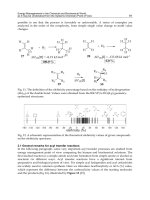
Fig. 11. Specific Fuel Use for ICE in Honda Insight
Fig. 10. Fuel saving components of HEV in city transport
7. Options
The serial PHEV is also good alternative for military vehicles and other vehicles for
operation out of civilization and out of grid, where the battery can be charged only from
Diesel-generator. Here is not the advantage of night charging from the plug, but the
generator with battery can serve as an independent power source for local DC or AC grid
Electric Vehicles – The Benefits and Barriers
90
from inverter. So it can be said, that such vehicle is more plug-out than plug-in, but its
composition is similar, maybe with higher ICE and generator power.
7.1 PHEV without generator
The last time concepts of PHEV suppose also solutions with mechanical connection of ICE to
wheels in highway traffic mode, when the EM and generator can be smaller and thanks
“shorter” drive chain the fuel consumption can be reduced comparing with electric chain.
Such concept can separate also the wheels driven by ICE and by EM and the typical front-
wheel drive vehicle can be can be equipped with electric rear-wheel drive.
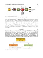
Fig. 12. PHEV without Generator
Because the charging from ICE is not very efficient and does not save the fuel, it is possible
to realize the vehicle, where each axis is driven by one motor (Fig.12). For short distance
trips the axis 1 is driven by EM supplied from battery and here can be also the energy
recuperated from braking or downhill rides. For the long distance trips on highways the ICE
drives the axis 2, which is connected to the first axis only by road surface, EM does not help
in drive, but it can again recuperate and in low speed drive, when the ICE does not work
with high enough efficiency, the driving torque from ICE can be bigger than is necessary
and EM can in generator run the surplus energy change into EE and charge the battery.
Instead of generator in Fig.3 here is the gearbox (manual or automatic) and the second
reduction and differential gearbox, both are from standard production. It is perfect union of
two independent drives available in emergency.
8. Conclusions
The reasons for PHEV are
Ecology, because the energy from renewable power sources reduces the carbon
emissions
Independence on oil import, because practically all suitable fuels for the ICE are
produced from oil. Coal hydrogenation was also developed in the war years and in
some tropical countries (like Brasilia) there are produced the alcohol fuels from plants
EM
Red + Dif
Gearbox 1
Fuel tank
ICE
Gearbox
Battery
Red + Dif
Gearbox 2
Plug-in Hybrid Vehicles
91
with sugar. For Diesel engines there is produced the oil from plants in the last years, to
replace the mineral oils.
Efficiency, especially in the city transport with low average speed and often stops and
traffic jam, where the combustion engine works with very low efficiency and also much
of fuel is spent in idle run.
Safety, due more automatic drive control in electric transmission drive train
The greatest advantage of the PHEV mass production is important oil consumption decrease
and increase of electricity production in the night hours when the price is minimal. The
distributors are also planning the smart grids in near future based on numerous batteries in
PHEV (or battery only vehicles) which can help to control the electrical energy balance in
grid for keeping the high quality parameters without voltage dips and sags.
9. Acknowledgment
The Czech Ministry of Education, Youth and Sport Financial Support, Program No. OC169
for COST Action 542, is acknowledged.
The financial support of the Czech Ministry of Defence Program for the Organization
Development (University of Defence in Brno) is acknowledged.
10. References
Bršlica, V. (2008) Super-capacitor integration into hybrid vehicle power source, In Proceeding
of International Conference on Renewable Energies and Power Quality (ICREPQ'08), pp.
6, ISBN 978-84-611-9290-8, Santander, Spain
Bršlica, V. (Sept. 2005), Co-generative Power Source for Electric Car, Proceeding of VPPC
2005, IEEE Cat. No.: 05EX1117C, (CD-ROM) ISBN 0-7803-9281-7, Chicago IL USA
Altairnano, NanoSafe Battery Technology, ALTI 070404, pp. 4, In web Altairnano.com
Buchmann, I., How to prolong lithium-based batteries, BatteryUniversity.Com
Stober, D. (2007), Nanowire battery can hold 10 times the charge of existing lithium-ion
battery, Stanford News service,
Fehrenbacher, K. (2009), Reva to Boost Range with Lithium-Ion Battery, Earth2tech,
Total Lithium-Ion Battery Sales Forecast to Double By 2012 to US$13.1B In Green car congress,
28.11.2008
Candace, K. et al., (2007), High-performance lithium battery anodes using silicon nanowires,
Nature Nanotechnology 3, 31 – 35 pp., December 16, 2007,
Soinoff, N. Lithium Battery Power Delivers Electric Vehicles to Market, Scientific & Technical
Information,
Deguzman, D. (2009), The race for car lithium battery is on, Green Chemicals,
January 7, 2009
Miller, C. (2008), Electric-Car Battery Makers Seek Federal Funds, December 26, 2008,
/>federal-funds/
Parker, R. (April 2009), Chevy Volt Battery Over-engineered Due To Unknowns,
Electric Vehicles – The Benefits and Barriers
92
Byoungwoo Kang & Gerbrand Ceder, Battery materials for ultrafast charging and
discharging, Nature 458, pp. 190-193, March 12, 2009
Weir, R. D. et al., (2008), Utilization of poly(ethylene terephthalate) plastic and composition-
modified barium titanate powders in a matrix that allows polarization and the use
of integrated-circuit technologies for the production of lightweight ultrahigh
electrical energy storage units (EESU), United States Patent 7,466,536, December 16,
2008
Weir, R. D. et al., (2006) Electrical-energy-storage unit (EESU) utilizing ceramic and
integrated circuit technologies for replacement of electrochemical batteries, United
States Patent 7,033,406, April 25, 2006
Ehrenber, G., Scott G. et al., (2008), Nanoparticle ultracapacitor, United States Patent
Application 20080316678 Kind Code A1, December 25, 2008
Ilyanok, M. A. (2007), Quantum Supercapacitor,” United States Patent 7,193,261 B2, March
20, 2007
Eisenring, R. (2008), Method of storing electricity in quantum batteries, United States Patent
Application 20080016681 Kind Code A1, January 24, 2008
2009 Tesla Roadster Technical Specifications,
Chevy Volt: Reasons for Use and Cost of Operation />reasons-for-use-and-cost-of-operation/ EEStore Energy storage unit,
Hund, T. (2004) Comparison Testing of Supercaps, Sandia National Laboratories,
Albuquerque, NM, November 2004
United States Patent 7 033 406,
Schindall, J. (2007), The Charge of the Ultra - Capacitors (Nanotechnology takes energy
storage beyond batteries)
Lockheed Martin Signs Agreement with EEStor, Inc. for Energy Storage Solutions, 10th
January 2008, />agreement-with-eestor/
Edgar, J. Brake Specific Fuel Consumption />Fuel-Consumption/A_110216/article.html
6
Fuel Cell Hybrid Electric Vehicles
Nicola Briguglio, Laura Andaloro, Marco Ferraro and Vincenzo Antonucci
CNR-ITAE, Via Salita S. Lucia sopra Contesse, Messina,
Italy
1. Introduction
Direct combustion of fuel for transportation accounts for over half of greenhouse gas
emissions and a significant fraction of air pollutant emissions. Because of growing demand,
especially in developing countries, emissions of greenhouse and air pollutants from fuels will
grow over the next century even with improving of technology efficiency. Most issues are
associated with the conventional engines, ICEs (internal-combustion engines), which primarily
depend on hydrocarbon fuels. In this contest, different low-polluting vehicles and fuels have
been proposed to improve environmental situation. Some vehicle technologies include
advanced internal combustion engine (ICE), spark-ignition (SI) or compression ignition (CI)
engines, hybrid electric vehicles (ICE/HEVs), battery powered electric vehicles and fuel cell
vehicles (FCVs). Fuel cell vehicles, using hydrogen, can potentially offer lower emissions than
other alternative and possibility to use different primary fuel option (Ogden, 2005) (Fig. 1.).
OIL NG COAL Biomass Wastes Nuclear-Hydro- Solar-Wind
Gasoline
Methanol,
F-T, or DME
Ethanol H
2
On board
fuel
processor
FUEL CELL
ICE or
ICE/Hybrid
H
2
-rich gas
Prime Energy
Source
Energy
carrier
Vehi cle
Fig. 1. Alternative fuel vehicle pathways.
A fuel cell vehicles fed by pure hydrogen are a “zero emission vehicle”, in fact the only local
emission are water vapour. But in this case it is important to consider the full fuel cycle or
“well-to wheels” emissions (fuel production, transport and delivery emissions). Primary
source for hydrogen production is crucial for the environmental performance of vehicles.
Hydrogen produced from renewable energy (i.e. wind or solar power connected with
electrolysis process) and used in fuel cells can reduce significantly emissions.Recent studies
Electric Vehicles – The Benefits and Barriers
94
concerning alternative fuels have been identified the fuel cell vehicles, using hydrogen, as
the most promising technology with reference to fuel cycle emissions. An analysis for
reductions in emissions and petroleum use is reported in following figure for different
hydrogen FCVs pathways.
Fig. 2. Well to wheels analysis of potential reduction in greenhouse gas emissions through
the hydrogen from different sources. (DOE 2009, 2010)
In order to develop technologies in ultra-low-carbon vehicles, European Commission
considers tree principal power train:
alternative fuels to burn in combustion engines to substitute gasoline or diesel fuel
include liquid biofuels and gaseous fuels (including LPG, CNG and biogas);
Electric vehicles;
Hydrogen fuel cell vehicles.
Advanced vehicles with internal combustion engines may not achieved full decarbonisation
alone (McKinsey & Company 2010) . It is therefore important to develop different
technologies to ensure the long-term sustainability of mobility in Europe.
According with this strategy, hydrogen fuel cell vehicles and battery electric vehicles have
similar environmental benefits (European Commission COM(2010 )186).
Today, in the light of numerous tests in a customer environmental (500 passenger cars –
both large and small – covering over 15 million kilometres and undergoing 90,000
refuellings, McKinsey & Company, 2010) FCVs may be considered technologically ready.
Moreover, they are still expensive and further research is needed to bring costs down. To
became competitive with today’s engine technologies, FCVs must reach large enough
markets to reduce the cost via mass production. The figure 3 reports the most important
technological challenges of FCVs for commercialization.
Despite great improvements in automotive fuel cell system of last years, significant issues
must be still resolved. These challenges include:
Development and cost of hydrogen refuelling infrastructures for direct-hydrogen FCVs;
Storage systems for hydrogen simultaneously safe, compact and inexpensive;
Cost reduction in fuel cell stack and durability;
Fuel Cell Hybrid Electric Vehicles
95
Fig. 3. FCVs: from demonstration to commercial deployment (McKinsey & Company, 2010).
The U.S. Department of Energy (DOE) is working towards activities that address the full
range of technological and non-technological barriers facing the development and
deployment of hydrogen and fuel cell technologies. The following figure shows the
program’s activities conducted to overcome the entire range of barriers to the
commercialization of hydrogen and fuel cells.
Fig. 4. The DOE program’s activities for fuel cell commercialization.
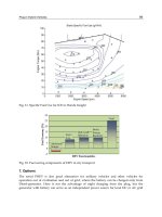
Regarding the stacks, the targets are to develop a fuel cell system with a 60 percent of
efficiency and able to reach a 5000-hours lifespan, corresponding to 240000 km at a cost of
$30/kW (at large manufacturing volumes) by 2015 (fig. 4.). The Program is also conducting
RD&D efforts on small solid-oxide fuel cell (SOFC) systems in the 1-to 10-kW range, with
possible applications in the markets for auxiliary propulsion units (APUs).
Electric Vehicles – The Benefits and Barriers
96
Fig. 5. Target of durability of FCVs in order to reach 240000 km (150000 miles). (DOE 2009).
DOE targets for transportation applications were derived with information from
FreedomCAR and Partnership, a collaborative technology organization of Chrysler Group
LLC, Ford Motor Company and General Motors Company. In table 1 are showed the targets
of direct hydrogen fuel cell power systems.
Characteristic Units Tar
g
et 2015
a
Ener
gy
efficienc
y
@ 25% of rated
p
ower
b
% 60
Ener
gy
efficienc
y
@ rated
p
ower % 50
Power densit
y
W/L 650
S
p
ecific
p
ower W/k
g
650
Cost
c
$/We 30
Transient response (time from 10% to
90% of rated
p
ower
)
s 1
Cold start up time to 50% of rated
power @–20°C ambient temperature
@+20°C ambient tem
p
erature
s
s
30
5
Start up and shut down ener
gy
d
from -20°C ambient temperature
from +20°C ambient tem
p
erature
MJ
MJ
5
1
Durabilit
y
with c
y
clin
g
hours 5,000
e
Unassisted start from low
tem
p
eratures
f
°C -40
a
Targets exclude hydrogen storage, power electronics and electric drive.
b
Ratio of DC output energy to the lower heating value (LHV) of the input fuel (hydrogen). Peak
efficiency occurs at about 25% rated power.
c
Based on 2002 dollars and cost projected to high-volume production (500,000 systems per year).
d
Includes electrical energy and the hydrogen used during the start-up and shut-down procedures.
e
Based on test protocols in Appendix D.
f
8-hour soak at stated temperature must not impact subsequent achievement of targets.
Table 1. DOE targets for automotive application of direct hydrogen fuel cell power systems
(DOE, 2010).
An other important issue in fuel cell vehicles commercialization is hydrogen storage.
Currently, compressed hydrogen is the principal technology used on board but the research
Fuel Cell Hybrid Electric Vehicles
97
is addressed towards a advanced materials able to store hydrogen at lower pressures and
near ambient temperature, in compact and light weight systems ( metal hydrides, chemical
hydrogen storage and hydrogen sorption).
In this chapter the prospects of fuel cell in transport application will be discussed and
particular attention will be paid to the CNR ITAE experiences. CNR ITAE is the National
Council Research of Italy that studies advanced technologies for energy. The Institute is
involved in different demonstration projects regarding the development of fuel cell hybrid
electric vehicles (FCHEVs) and in particular minibus, citycar, bicycle and tractor. Some kind
of projects are addressed to different markets, in particular the so-called “early markets” are
deal with. In this case the powertrain is electric and hybrid because it is composed by
known technologies, like batteries, but also by supercaps and fuel cells that are innovative
technologies. Fuel cells have a small size because are used like on board batteries recharge,
“range extender” configuration, allowing to increase the range of traditional electric
vehicles. The lower fuel cell power means a reduction in terms of stack size then a less cost
of it as well as hydrogen storage amount.
Other one kind of projects is instead addressed to a future market. The configuration used is
the “full power fuel cell”, in which FCVs have a big size of power close the electric motor
power. The full power fuel cell vehicles are provided with innovative components such as
radio systems (information technology systems - ITS) able to broadcast with other similar
vehicles and fleet managing station. They represent a new concept of vehicle because they
are a high-tech products, equipped with hardware and chassis made with new light
materials and with a platform having interchangeable upper bodies.
2. Fuel cell technology for transport applications
Proton Exchange Membrane Fuel Cells (PEMFC) are the most used technology in FCVs. In
part, this dominance is due to large number of companies interested in PEMFC
development. In technical terms, PEM fuel cells have high power density, required to meet
the space constraints in vehicles, and a working temperature of about 70 °C allowing a rapid
start-up. The electric efficiency is usually 40-60% and the output power can be changed in
order to meet quickly demanded load. Other characteristics of PEMFC systems are
compactness and lightness. As a result of these characteristics, PEMFC are considered the
best candidates for mobile applications. The disadvantages of this technology are sensitive
to fuel CO impurities and expensive catalyst, higher CO levels result in loss of fuel cell
performance. Furthermore, the electrolyte must be saturated with water and the control of
the anode and cathode streams therefore becomes an important issue. In transport
applications this technology is used in hybrid configuration with electricity storage devices,
such as batteries or super capacitors.
Today real competitors in transport market are SOFC (Solid Oxide Fuel Cell) systems,
particularly suited for auxiliary power unit (APU) such as heating, air conditioning, etc
(heating, air-condition etc ). SOFCs are characterised by their high working temperature of
800-1000°C. There are two configuration of stack, tubular and planar. The tubular concept is
suitable for large-scale stationary applications while the planar concept is preferred for
transport application tanks to the higher power density.The SOFC applications in vehicles
are limited to APU rule due to long start-up time and slow dynamic behaviour caused by
high temperature operation. However, it is also considered an important option for
auxiliary power units on board of vehicles in the 5 kW range. The power density of the
SOFC is in the range of 0.15-0.7 W/cm
2
but high temperature corrosion is a problem that
Electric Vehicles – The Benefits and Barriers
98
requires the use of expensive materials. Delphi automotive and BMW companies have
already been examined this technology in prototype vehicles.
Other different typologies of fuel cells used in transport are the AFC (Alkaline Fuel Cell).
The use of this kind of FC is, today, limited if compared with other FC technologies. Several
units are installed in niche transport sectors such as motorbikes, forklift trucks, marine and
space applications. Several installations (80%) were introduced before 1990 and used in
space applications especially. The rest were installed in transportation development and
demonstration vehicles. After 1990 some units were installed in light duty, portable and
small stationary end-use. When PEM units were introduced in the 1980s, the interest was
shifted to this fuel cell alternative, particularly for the transport sector. Recently, some
companies have been considered AFC technology for operation in stationary and portable
application. The main problem of this technology is the carbon dioxide poisoning: small
amounts of CO
2
reduce the conductivity of electrolyte. As consequence of this, pure
hydrogen must be used. Besides, air needs to be cleaned from CO
2
, which limits the
application for terrestrial applications considerably.
Finally, DMFC (Direct Methanol Fuel Cell) technology is used to power portable
applications and in some niche transport sector such as marine, motorbikes and APU. In the
year 2000, Ballard and Daimler Chrysler installed a DMFC system on a light duty but after
no other vehicles have been developed. Some years ago DMFC had been considered a
promising technology because methanol, that is a liquid fuel, allows to maintain all
refuelling infrastructures. However if compared with PEMFC, the DMFC power density is
lower but the high energy density of fuel (methanol) has potential to replace batteries with
micro fuel cell systems.
FC
technology
Working
temperature
Efficiency Automotive
applications
Advantages Disadvantages
PEM 70-90°C 50-60% Buses, Niche
transport, li
g
ht dut
y
vehicles, APU (niche
transport vehicles)
high power
density
rapid start-up
capacity to
meet quickly
demand load
Solid
electrolyte
sensitive to fuel
CO impurities
expensive
catalysts
SOFC 700-1000 °C 50-60% APU ((niche
transport vehicles)
Tolerance to
fuel CO
impurities
Fuel flexibility
Solid
electrolyte
Long start-up
Slow dynamic
load behaviour
Hi
g
h temperature
corrosion of
components
DMFC 60-130°C 40% APU (niche
transport vehicles)
Storage of
liquid fuel
(methanol)
Low power
density
high noble metal
loadings
AFC 90-100 °C 50-60% APU (niche
transport vehicles)
Low cost
components
Sensitive to CO2
in fuel and air
Table 2. Fuel Cell technologies for transport applications.
Fuel Cell Hybrid Electric Vehicles
99
Table 2 summarizes fuel cell technologies for transport sector by application. The used
technologies are PEM, SOFC, AFC and DMFC while PAFC (Phosphoric Acid Fuel Cell) and
MCFC (Molten Carbonate Fuel Cell) systems are generally suitable to provide stationary
power and generation of heat for residential and industrial applications.
3. The current market of FCVs
Fuel cell vehicles are still in development and demonstration phase. All automakers have
substantial development programs underway. Most attention is focused on the use of
PEMFCs for transportation applications. Actually, PEM technology is used in different
application as shown in figure 5. The majority of units installed globally are used for
portable applications. Niche transportation, light duty vehicles and buses are only around
15% of total installed units because the request is low compared to the other markets.
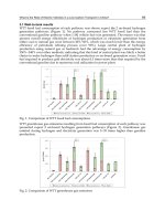
Fig. 6. Percentage of PEM units installed by application (Gemma Crawley, 2006).
Fig. 7. Buses fuel cells units produced from 1994 to 2008 (Lisa Callaghan Jerram, 2008).
The PEFC systems was chosen for providing primary power train for buses involved in the
clean urban transport for Europe (CUTE) (2003-2006). A total of 27 Mercedes-Benz Citaro
buses, equipped with fuel cell power train, were used on three continents. Figure 7 shows
Electric Vehicles – The Benefits and Barriers
100
the buses units number produced per years, the peak number is in 2003 when started the
CUTE project. In term of fuel cell bus deployment, Europe is leader with 53% of total
deployments and 17 cities involved in demonstration projects. Asia’s projects are focused in
Japan, China and South Korea, in USA several activities are presented in California (fig. 8).
With regard to the regions of manufacture the situation mirrors the deployments with
Europe 67% of total. The reason of that is the CUTE project, supported by Mercedes Benz
fuel cell Citaros, and a Belgian fuel cell buses company, Van Hool.
Fig. 8. Fuel Cell bus deployment (a) and region of manufacture (b) from 2003 to 2008 (Lisa
Callaghan Jerram, 2008).
Such as in buses market, in duty vehicles the technology choice is PEM. The annual
distribution of units is not constant and reflects the pre-commercial nature of this market
(fig. 9). Besides, the targets of past are shifted into next years. The main automaker involved
in this sector are Honda, General Motors, Nissan, Hyundai-Kia and Toyota.
Fig. 9. Annual New Light Duty Vehicle (Lisa Callaghan Jerram, May 2009).
Figure 10 reports the manufacture and deployment percentage by region. For 2007-2009
(projected) Asia and North America have become the major areas of manufacture.
California, with the presence of infrastructures and the ZEV mandate, is a leading market
for fuel cell vehicles. Germany, due to government programs, is a promising country for fuel
(b)(a)
Fuel Cell Hybrid Electric Vehicles
101
cell market. With regard to Asia, fuel cell vehicles are used as small fleets leased to
government officials.
Fig. 10. Light Duty Vehicle deployment (a) and region of manufacture (b) 2007-2009 (Lisa
Callaghan Jerram, May 2009).
The Honda fuel cell concept car is shown in figure 11 witch illustrates how modern fuel cell
systems can be packaged into a small light-duty vehicles. Like most FC cars, the vehicle is
equipped with a compressed hydrogen storage system.
Fig. 11. Fuel cell concept car (manufacturer Honda, type FCX Clarity).
In table 3 the last fuel cell vehicles produced by some carmakers are listed. FC manufacture,
range and fuel type are reported.
Transport sector comprises applications as aircraft and aerospace, scooters, motorbikes and
other two- and three-wheeled vehicles, materials handling vehicles such as forklift trucks,
trains and the ‘other’ category, including such applications as wheelchairs and mobility
assistance vehicles. Annual growth from 2005 through 2008 is showed in figure 12. The units
installed in 2008 regard principally materials handling vehicles, scooters and motorbikes
and the ‘other’ category including mobility assistance vehicles, each of which saw tens to
hundreds of units deployed.
(a)
(b)
Electric Vehicles – The Benefits and Barriers
102
Automaker Vehicle type Year Engine type FC manufacturer
FC
size/type
Range
(mi/km)
Fuel type
Audi Q5 HFC 2010
FC/batter
y
h
y
brid
N/a 131 bhp N/a
Compress.
h
y
dro
g
e
n
AVL list
GmbH
AVL FCC: 4-5 2010
EV with FC
ran
g
e extender
N/a 3 kW PEM 150 km
34L CGH @
200 bar
BMW
FC/h
y
brid electric
1-Series
2009
FC/batter
y
h
y
brid
UTC Power N/a N/a N/a
Daimler
Mercedes-Benz F
800
2010
FC/battery
hybrid
N/a N/a
18 mi
batter
y
/plus
375 mi
h
y
dro
g
e
n
Compress.
hydrogen
Fiat/Alfa
Romeo
MiTo 2010 N/a N/a N/a N/a N/a
Fiat Panda 2007 Fuel Cell Nuvera 60 kW PEM 200 kW
Compress.
hydrogen
Ford Motor
Company
HySeries Edge 2007
Fuel Cell plug-
in hybrid
Ballard
HySeries
Drive
491 km N/a
GM Provoq 2008
FC/battery
hybrid
GM 88 kW PEM 483 km
Compress.
hydrogen
Honda Fc Sport 2008 Fuel Cell Honda PEM N/a
Compress.
hydrogen
Honda FCX Clarity 2007 Fuel Cell Honda
100
kW/PEM
570 km
Compress.
hydrogen
Hyundai Tucson ix35 FCEV 2010
FC/supercap
hybrid
N/a
100
kW/PEM
650 km
Compress.
hydrogen
Kia
Borrego/Majoave
FCEV
2008
FC/battery
hybrid
Ballard
115
kW/PEM
685 km
Compress.
hydrogen
Microcab
Industries
Limited
Microcab 2008 Fuel Cell N/a N/a 160 km
Compress.
hydrogen
Mor
g
an LIFECar 2008 Fuel Cell QinetQ 22 kW/PEM 402 km N/a
Pininfarina Sintesi 2008
FC/batter
y
h
y
brid
Nuvera
Four 20 kW
PEM
N/a N/a
PSA Peu
g
eot
Citroen
FiSyPAC 2009
FC ran
g
e
extender
N/a N/a 496 km N/a
Renault Scenic FCV H2 2008
FC/battery
hybrid
Nissan 90 kW 240 km N/a
Shan
g
hai
Automoti-ve
Industry
Corp.
Shangha 2007 Fuel Cell ShenLi 60 kW/PEM N/a N/a
Suzuki SX4-FCV 2008 Fuel cell GM 80kW/ PEM 250km
Compress.
h
y
dro
g
e
n
Tecnalia H2CAR 2008
Fuel cell/
batter
y
h
y
brid
N/a 5kW/ PEM N/a
Compress.
h
y
dro
g
e
n
Toyota FCHV-adv 2008
Fuel cell/
batter
y
h
y
brid
Toyota FC stack N/a 830km N/a
Volvo C30 2010
Fuel cell/
battery hybrid
Powercell
Sweden
N/a 400 km
H
y
dro
g
e
n
(reformed
onboard
from
g
asoline
)
VW Passat Lingyu 2008
Fuel
cell/batter
y
SAIC (Shan
g
hai
VW parent co.)
55kW/ PEM 300km N/a
Table 3. Some recent fuel cell Vehicles prototype by automaker (Fuel cell 2000, 2011).
Fuel Cell Hybrid Electric Vehicles
103
Fig. 12. Niche transportation: annual growth (Jonathan Butler, July 2008).
The technologies used for this application are PEM and DMFC, very little units installed are
SOFC (fig. 13). In particular, there is most units PEM in aerospace and aircraft sector, a two
thirds to one third split between PEM and DMFC in the scooters and motorbike market. In
the materials handling market, almost exclusively PEM units are used. In the ‘other’
category, there are roughly six times the number of DMFC units compared with PEM units.
Fig. 13. Percentage of units shipment by technologies (Jonathan Butler, July 2008).
Marine and APU market is another interesting application where fuel cells have about 7000
units installed into 2008. Starting with very low units installed in 2005 the numbers
increased during 2007/2008.
Electric Vehicles – The Benefits and Barriers
104
Fig. 14. Fuel cells units installed in niche transportation sector (APU and marine) from 2005
through 2008 (Dr. Jonathan Butler, 2008).
In terms of technology, DMFC is the principal chose thanks to the liquid fuel and flexibility
of refilling. The followed figure shows the percentage by technology. Number of PEM units
are limited to APU applications for on board yachts due to their silent operation.
Very interesting is the SOFC technology used mainly for APU demonstration units for road
vehicles and marine vessels. In fact, units installed in this transport sector are higher than in
large stationary applications (Gemma Crawley, 2007). In this sector SOFC units are used as
APUs to supply auxiliary power to selected vehicles. Companies involved in development
of automotive system for fuel cell, as Delphi Automotive Systems, believe in SOFC
technology for the high efficiency, simply reforming technology and less stringent fuel
requirements. The majority fuel cell manufacturer in transportation sector are indicated in
table 4.
Fig. 15. APU and Marine sectors: percentage by technology 2007/2008 (Dr. Jonathan Butler,
2008).
Fuel Cell Hybrid Electric Vehicles
105
Manufacturer Application size Technology
Ballard
Transportation/bus/light
mobility
4 - 85 kW PEM
General Hydrogen Small/medium/large trucks / PEM
SFC Smart Fuel Cell Mobile/niche transport
600 - 1600
Wh/day
DMFC
UTC Power Transportation 120 kW PEM
Hydrogenics Mobility application 4 – 65 kW PEM
Nuvera FC APU, transportation 5 – 82 kW PEM
Delphi Automotive
System
APU 1-5 kW SOFC
Table 4. Fuel cell manufacturers for transport applications.
4. Vehicles configuration
Fuel cell vehicles are electric vehicles powered by batteries and fuel cell. There are different
configurations for fuel cell hybrid electric vehicles (FCHEVs). In particular the configuration
depends on the desired hybridization level and on the fuel cell and batteries rules.
In conventional electric vehicles batteries provide power to the electric motor, in the
FCHEVs batteries and fuel cell are connected in a parallel system and together provide
power.
Figure 16 shows a fuel cell stack connected with a DC/DC converter needed to provide a
regulated voltage at the output. Battery pack is connected with auxiliary devices and with
fuel cell. The DC/AC inverter converts the direct current (DC) in alternate current (AC) in
order to fed electric motor. The motor is able to recover part of energy that would normally
be lost due to braking (regenerative braking). This recovered energy is used to recharge
batteries.
Fuel
Cell Stack
DC/DC
Conv
Inv
Battery
Auxiliary
Devices
Motor
Regeneration,
Recharge Bat when needed
Assist fuel cell when needed
Power vehicle at
high battery SOC
Cycle requirement
Fig. 16. Fuel Cell Hybrid Electric Vehicle configuration
Electric Vehicles – The Benefits and Barriers
106
The sizes of batteries and fuel cell define the hybridization level and the configuration.
A conventional electric vehicle (full battery) presents intrinsic limits like the range (that is
function of batteries capacity) and recharge time (about 6-8 hours), that can reduce their use.
FCHEVs allow to increase the range, in terms of working hours or distance, because it is a
function of the on board stored hydrogen and the hydrogen refuelling time isn’t comparable
to the batteries recharging time.
In the first configuration, called "total fuel cell" or "full power fuel cell", the electric drive motor
is totally fed by fuel cell and a small battery can be installed just for the vehicle start up or
for peak power. In this case the fuel cell power is close the electric motor power. A similar
architecture, having a big size of fuel cell, means a great quantity of stored hydrogen (also
depending on the required range) and high costs.
Another configuration consists of an architecture in which the fuel cell is used as APU
(auxiliary power unit) and provides the electrical power required by the auxiliary devices.
In this case the fuel cell size is very small and its function is essentially addressed to cover
small loads like air conditioning, electric windows, lights, etc.
Finally, the "range extender" configuration is characterized by a small size fuel cell used like
on board batteries recharge. This solution, depending on the on board stored hydrogen,
allows to increase the range of traditional electric vehicles. Using this configuration it is
possible to define a specific batteries recharge strategy; in particular the batteries can be
recharged when the electric motor doesn't require load, i.e. during the stops and at the
terminus. In some case the fuel cell can contribute to the electric traction providing energy
when the vehicle runs also. In this way the fuel cell works in optimal operation conditions at
a fixed power, avoiding the load following operation that could cause thermal and
mechanical stress of materials.
Moreover, the lower fuel cell power means a reduction in terms of stack size then a less cost
of it as well as hydrogen storage amount.
5. CNR ITAE challenges and activities
The automotive strategy of CNR-ITAE is to investigate the fuel cell technology in order to
evaluate the stack behavior and its integration in a system, addressing the research towards
an efficient system interface and architecture trade off. This includes hydrogen stack
modules as well as reformate stack modules. The principal issues regard efficiency, cost,
durability and manufacturing. The research activities is focused on SOFC and PEM
technologies for applications with hydrogen and Reformed hydrocarbon (NG, GPL). In fact,
although the long term target is to implement hydrogen as fuel, since the current limited
hydrogen infrastructures, other fuel (such as Reformed NG) can be a short term solution
(figure 17).
The projects in which CNR ITAE is involved concern electric vehicles realization, having an
electric motor like driving force. This kind of projects are addressed to different markets, in
particular the so-called “early markets” are deal with. In this case the powertrain is electric
and hybrid because it is composed by known technologies, like batteries, but also by
supercaps and fuel cells that are innovative technologies. Fuel cells have a small size
because are used like on board batteries recharge, “range extender” configuration, allowing
to increase the range of traditional electric vehicles. This approach is a way to introduce the
FC technology gradually thanks to the lower power and costs.
Fuel Cell Hybrid Electric Vehicles
107
H
2
-storage
Fuel Cell System Transport Application
hydrogen
Electrical
Energy
Air
Water
Long-term solution
Short-term solution
Fuel
Processor
Fuel Cell System Transport Application
hydrogen
Air
Water
Fuel
(e.i. NG)
Air
Exhaust
Electrical
Energy
Fig. 17. Fuel options for fuel cell power generation.
The other one kind of projects is instead addressed to a future market. The configuration
used is the “full power fuel cell”, in which FCs have a big size of power close the electric
motor power. The full power fuel cell vehicles are provided with innovative components
such as radio systems (information technology systems - ITS) able to broadcast with other
similar vehicles and fleet managing station. They represent a new concept of vehicle because
they are a high-tech products, equipped with hardware and chassis made with new light
materials and with a platform having interchangeable upper bodies.
Demonstration projects regarding the development of fuel cell hybrid electric vehicles
(FCHEVs) and in particular minibus, citycar, bicycle, tractor and airplane.The tractor
projects intends to demonstrate that the fuel cell can be applied in the farm context because
hydrogen could be produced on site using different methods (biomass, wind energy,
photovoltaic). In this case the hurdle of hydrogen distribution is avoided.
The research activities of CNR ITAE are supported by numerous partners involved in fuel
cell development. This includes collaborations and with fuel cell developers like Nuvera
Fuel Cell, SOFCPower and with industrial partners.
The most of important projects in automotive sector which CNR ITAE is involved are
“Meccano”, “BHYKE”, “HY-TRACTOR” and “H-BUS”.
The project, called “MECCANO”, is to develop a highly evolved concept vehicle which
offers competitive advantages in terms of optimized ergonomics, low running costs, high
levels of safety, modularity and low environmental impact. This new product wants to meet
societies demand for reduced congestions, low road-space occupation and improved
intermodality with public transportation systems. In this context, the vehicle is characterized
by the following features (fig. 18):
Electric Vehicles – The Benefits and Barriers
108
- Very highly efficient propulsion system: the powertrain configurations include full-
power fuel cell, plug-in battery electric, battery electric with auxiliary motor-generator
(series hybrid), and parallel hybrid with methane fuelled internal combustion engine.
- Compact body and short vehicle length (approx. 3m) with high vehicle habitability.
- Advanced technologies for integrated preventive, active and passive safety, in order to
attain the highest levels of Euro-NCAP consumer ratings.
- Latest solutions for human-machine and machine-infrastructure interactions and
communication personalized depending on the user and on the specific application.
- This economic and ecological urban vehicle aspires to become an ideal mode of
transport for environment-aware individuals and municipal authorities. This dual-use
concept (ie. individuals as conventional cars or as a means of personalised public
transport) introduces radically new opportunities for vehicle design: a) the
development of a platform: chassis and low part of the vehicle can be configured in a
highly flexible manner in order to accommodate the different propulsions listed above;
b) the design of two vehicle bodies and their relative interiors offering different styles
and appropriate technologies.
In MECCANO project several automotive companies are directly involved (FIAT, Michelin,
Magneti Marelli, Marangoni, ecc.) in conjunction with research institutes.
Fig. 18. Meccano project.
The bicycle project “BHYKE” is the study of an innovative electric bicycle in joint venture
with an Italian company, called TRE S.p.A. (Tozzi Renewable Energy). The bike, having
pedal assistance, is provided with a 250 W fuel cell and a hydrogen solid state storage
cylinder of 900 Sl at 12 bar. The targets for this project are: a range of 130-150 km, a
maximum speed of 35 km/h and total weight of 30 kg (fig. 13). The aim of the project is to
realize, through a new concept of bike sharing service, a representative sample of field test
of hydrogen refuelling station from renewable energy (photovoltaic and wind).
Fig. 19. Hydrogen bicycle and technical characteristics.