Nghiên cứu tính toán vật lý nơtron, thủy nhiệt và quản lý vùng hoạt để vận hành an toàn và sử dụng hiệu quả lò phản ứng hạt nhân Đà Lạt
Bạn đang xem bản rút gọn của tài liệu. Xem và tải ngay bản đầy đủ của tài liệu tại đây (2.97 MB, 126 trang )
MINISTRY OF EDUCATION
AND TRAINING
MINISTRY OF SCIENCE AND
TECHNOLOGY
VIETNAM ATOMIC ENERGY INSTITUTE
-----------------------------
NGUYỄN KIÊN CƯỜNG
Study on neutronics, thermal hydraulics and core
management for safe operation and effective utilization of the
Dalat Nuclear Research Reactor
A thesis submitted in fulfillment of the requirements for the degree of
Doctor of Philosophy
HÀ NỘI – 2023
MINISTRY OF EDUCATION
AND TRAINING
MINISTRY OF SCIENCE AND
TECHNOLOGY
VIETNAM ATOMIC ENERGY INSTITUTE
-----------------------------
NGUYỄN KIÊN CƯỜNG
Study on neutronics, thermal hydraulics and core
management for safe operation and effective utilization of the
Dalat Nuclear Research Reactor
DOCTORAL THESIS
Subject: Atomic and Nuclear Physics
Code number: 9-44-01-06
Supervisor: Assoc. Prof. PhD. NGUYỄN NHỊ ĐIỀN
Hà Nội – 2023
1
ACKNOWLEDGEMENTS
I would like to express my deep gratitude to my supervisor Assoc. Prof. PhD.
Nguyễn Nhị Điền for his valuable assistance and encouragement throughout my
research works.
I would like to thank all my colleagues at the Reactor Center, particularly Mr.
Huỳnh Tôn Nghiêm, Mr. Lê Vĩnh Vinh, Mr. Lương Bá Viên and Mr. Nguyễn Minh
Tuân for their generous support, insightful discussions and contributions to my study.
I appreciate the staff of the Dalat Nuclear Research Institute, Nuclear Training
Center, and Vietnam Atomic Energy Institute for their kind assistance during my
research.
I want to send my appreciation to Assoc. Prof. PhD. Vương Hữu Tấn, Assoc.
Prof. PhD. Phạm Đình Khang, Assoc. Prof. PhD. Nguyễn Xuân Hải, PhD. Trần Chí
Thành, Assoc. Prof. PhD. Nguyễn Tuấn Khải, Assoc. Prof. PhD. Trịnh Anh Đức for
their encouragement for my research works.
I am grateful to Ms. Nguyễn Thúy Hằng for all of her assistance with the
administrative aspects to my research.
Finally, I would like to express my gratitude to my parents, my wife, my son
and my daughter, who always provided me with theconfidence and motivation tocompletethe thesis.
2
BOC
BWR
CFD
CHF
CITATION
DNBR
DNRI
DNRR
ENDF
FA
FIR
FPD
GA
HANARO
HEU
IAEA
IFA
JEFF
JENDL
LEU
MCNP
MPI
MTR
NPP
ONBR
PVM
PWR
ReR
RERTR
RIA
SA
SaR
ShR
SRAC
TRIGA
VVER
WIMSD
1-D
2-D
3-D
LIST OF ABBREVIATIONS
Beginning of Cycle
Boiling Water Reactor
Computational Fluid Dynamics
Critical Heat Flux
Nuclear Reactor Core Analysis Code
Departure Nucleate Boiling Ratio
Dalat Nuclear Research Institute
Dalat Nuclear Research Reactor
Evaluated Nuclear Data File
Fuel Assembly
Flow Instability Ratio
Full Power Day
Genetic Algorithm
Korean Research Reactor
Highly Enriched Uranium
International Atomic Energy Agency
Instrumental Fuel Assembly
Joint Evaluated Fission and Fusion (European Evaluated)
Nuclear Data Library
Japanese Evaluated Nuclear Data Library
Low Enriched Uranium
Monte Carlo N-Particle Computer Code
Message Passing Interface
Material Testing Reactor
Nuclear Power Plant
Onset Nucleate Boiling Ratio
Parallel Virtual Machine
Pressurized Water Reactor
Automatic Regulating Rod
Reduced Enrichment of Research and Test Reactor
Reactivity Insertion Accident
Simulated Annealing
Safety Rod
Shim Rod
Standard Reactor Analysis Code
Training, Research, Isotope Production of General
Atomics
Water-Water Energetic Reactor
Winfrith Improved Multigroup Scheme
Unidimensional
Bidimensional
Tridimensional
3
CONTENT
ACKNOWLEDGEMENTS ................................................................................................... 2
LIST OF ABBREVIATIONS ................................................................................................ 3
CONTENT ................................................................................................................................. 4
LIST OF TABLES.................................................................................................................... 9
INTRODUCTION .................................................................................................................. 10
CHAPTER 1. GENERAL OVERWIEW .......................................................................... 20
1.1. Motivation of the thesis ................................................................................................... 20
1.2. General introduction about the DNRR ....................................................................... 21
1.2.1. History, structure and reactor core arrangement ....................................................... 21
1.2.2. Fuel of VVR-M2 HEU and LEU ................................................................................... 28
1.2.3. Neutronics characteristics of the DNRR ...................................................................... 30
1.2.4. Thermal hydraulics characteristics of the DNRR........................................................ 32
1.3. The development of computer codes for reactor calculation in the world ........... 33
1.4. The research situation about research reactor in Vietnam..................................... 35
1.5. Reactor kinetics in three dimensions ........................................................................... 38
1.6. Burn-up calculation for core and fuel management ................................................. 39
CHAPTER 2. CALCULATION MODELS FOR THE DALAT NUCLEAR
RESEARCH REACTOR USING LEU FUEL ................................................................ 41
2.1. Neutronics calculation models....................................................................................... 41
2.1.1. Deterministic code .......................................................................................................... 41
2.1.2.1. Lattice cell model......................................................................................................... 41
2.1.2.2. Whole core model ........................................................................................................ 46
2.1.2. Calculation model for computer codes using Monte Carlo method .......................... 48
2.2. Thermal hydraulics calculation for the DNRR ......................................................... 50
2.3. Reactor kinetics application for the DNRR ................................................................ 53
2.3.1. Preparation group constants for the PARCS code....................................................... 53
2.3.2. Calculation model for the DNRR using the PARCS code ......................................... 54
2.4. Burn-up calculation for the DNRR .............................................................................. 54
2.4.1. Development MCDL computer code ........................................................................... 54
2.4.2. Application of MCDL for burn-up and refueling calculation for LEU core ............ 61
2.5. Summary of Chapter 2 ................................................................................................... 62
CHAPTER 3. RESULTS AND DISSCUSSIONS ............................................................ 64
3.1. Neutronics and thermal hydraulics for LEU core .................................................... 64
4
3.1.1. Neutronics calculation results ........................................................................................ 64
3.1.1.1. Neutronics characteristics of the HEU and LEU VVR-M2 fuel types.................... 64
3.1.1.2. Criticality, reactivity, control rod worths.................................................................. 67
3.1.1.3. Excess reactivity, control rod worth, beryllium rods ............................................... 72
3.1.1.4. Neutron flux distribution ............................................................................................. 74
3.1.1.5. Power peaking factor .................................................................................................. 78
3.1.1.6. Feedback reactivity temperature coefficients and void factor ................................ 80
3.1.1.7. Kinetics parameters..................................................................................................... 81
3.1.2. Thermal hydraulics calculation results ......................................................................... 81
3.1.2.1. Validation of the PLTEMP code ................................................................................ 81
3.1.2.2. Steady state of PLTEMP code without hot channel factors .................................... 85
3.1.2.3. Steady state of PLTEMP code with hot channel factors.......................................... 87
3.2. Kinetics calculation results for LEU core ................................................................... 88
3.2.1. Calculation results from the Serpent and PARCS codes at steady state condition .. 88
3.2.2. Calculation and experiment results during increasing power of the DNRR from 80%
to 100% ...................................................................................................................................... 90
3.2.3. Simulation of the accident when uncontrolled withdrawal of one control rod at
nominal power ........................................................................................................................... 93
3.2.4. Simulation of the changing of power when inserting positive reactivity smaller than
10 cents....................................................................................................................................... 95
3.3. Burn-up calculation results............................................................................................ 97
3.3.1. Validation of the MCDL code ....................................................................................... 97
3.3.2. Calculation results of the HEU core ........................................................................... 102
3.3.3. Calculation results of the LEU core ............................................................................ 106
3.4. Summary of Chapter 3 ................................................................................................. 113
CONCLUSIONS ................................................................................................................... 113
NEW CONTRIBUTIONS OF THE THESIS ................................................................ 117
LIST OF PUBLICATIONS ................................................................................................ 117
REFERENCES...................................................................................................................... 119
5
LIST OF FIGURES
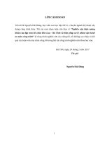
Fig. 1.1. Cross sections of the DNRR in axial and radial directions .................................... 22
Fig. 1.2. Annual operation time of the DNRR from 1984 to 2011 (the core configuration
using HEU fuel and mixed cores)............................................................................................ 27
Fig. 1.3. Annual operation time of the DNRR from 2012 to 2022 (using LEU fuel) ........ 27
Fig. 1.4. Specific dimensions and geometry of the VVR-M2 fuel type .............................. 29
Fig. 2.1. Calculation model for VVR-M2 FA of the DNRR ................................................ 42
Fig. 2.2. Calculation model for group constants of the neutron trap .................................... 44
Fig. 2.3. Calculation model for lattice cells in side the DNRR core .................................... 45
Fig. 2.4. Calculation model for lattice cells outside the DNRR core ................................... 46
Fig. 2.5. Calculation model for the DNRR using the REBUS-PC and CITATION codes
(a- model in REBUS-PC and b- model in CITATION)........................................................ 47
Fig. 2.6. Calculation model in axial direction using the CITATION code ......................... 48
Fig. 2.7. Model cross section of VVR-M2 FA in MCNP code for normal calculation and
power peaking factor calculation (a- FA; b- FA model in the MCNP code and c-example
of detailed power peaking factor calculation inside FA) ....................................................... 49
Fig. 2.8. Calculation model for a) SaRs or ShRs, b) ReR, c) beryllium rod, d) aluminum
chock rod, e) wet or dry irradiation channels, f) the neutron trap......................................... 50
Fig. 2.9. Calculation model for full core of the DNRR using the MCNP code .................. 50
Fig. 2.10. The DNRR model calculation for the PLTEMP/ANL code and LEU core with
92 FAs ........................................................................................................................................ 51
Fig. 2.11. Super-cell model in the Serpent code to create group constants of ShR ............ 54
Fig. 2.12. Calculation model of the DNRR using the PARCS code.................................... 54
Fig. 2.13. General structure of the MCDL code .................................................................... 58
Fig. 2.14. Burn-up chain model of actinide and fission products isotopes in the MCDL
code............................................................................................................................................. 60
Fig. 3.1. Neutron spectrum of HEU and LEU VVR-M2 fuels with 108 neutron energy
groups in average power (89 HEU FAs core and 92 LEU FAs core).................................. 66
Fig. 3.2. Neutron spectrum of LEU VVR-M2 fuel type with different calculation libraries
..................................................................................................................................................... 67
Fig. 3.3. Critical core configuration with a) 72 FAs and b) working core with 92 FAs .... 70
Fig. 3.4. Thermal neutron flux distribution in the radial direction (unit ×1012 n/cm2.s)..... 77
Fig. 3.5. Relative power distribution in axial direction and depending on control rod
positions of working core of 92 LEU FAs.............................................................................. 79
6
Fig. 3.6. Calculation results of relative power distribution in the working core using 92
LEU FAs (upper value from MCNP and below value from REBUS) ................................ 80
Fig. 3.7. Comparison of the measured cladding and coolant temperatures of the HEU core
to validate the PLTEMP/ANL code ........................................................................................ 82
Fig. 3.8. The HEU VVR-M2 IFA of the DNRR ................................................................... 83
Fig. 3.9. Axial power distribution of the hottest FA (at cell 10-5) calculated by the MCNP
code for 25-cm insertion of 4 ShRs ......................................................................................... 84
Fig. 3.10. Calculation results at nominal power without errors and uncertainties in the
hottest FA ................................................................................................................................... 86
Fig. 3.11. Comparison of the fuel cladding and coolant temperatures at different reactor
power levels ............................................................................................................................... 87
Fig. 3.12. Calculation results at nominal power with systematic errors .............................. 87
Fig. 3.13. Calculation results at nominal power with systematic and random errors ......... 88
Fig. 3.14. Calculation results of the increasing power of the DNRR from 80 to 100%..... 91
Fig. 3.15. Experimental data of the changing position of ReR (TD) when increasing
reactor power from 80% to 100% ........................................................................................... 91
Fig. 3.16. Position of ReR (TD) and power when increasing reactor power from 80% to
100%........................................................................................................................................... 92
Fig. 3.17. Reactivity and reactor power when increasing reactor power from 80 to 100%
..................................................................................................................................................... 92
Fig. 3.18. Calculation results the changing position of ReR (TD) when increasing power
from 80 to 100%........................................................................................................................ 93
Fig. 3.19. Power and reactivity in the accident of uncontrolled withdrawal of the ShR
number 1 with and without feedback reactivity temperature coefficients of water and fuel
..................................................................................................................................................... 94
Fig. 3.20. Reactor power transient of one ShR withdrawal from operating power 100% . 95
Fig. 3.21. Reactor power and reactivity transient of ShR number 1 uncontrolled
withdrawal from operating power 100% ................................................................................ 95
Fig. 3.22. Power and reactivity changing when inserting 10 cents reactivity ..................... 96
Fig. 3.23. The changing of the ReR (TD) when inserting 10 cents ..................................... 97
Fig. 3.24. Experimental data of power (D1) and ReR (TD) position when inserting 10
cents ............................................................................................................................................ 97
Fig. 3.25. a) Infinite multiplication factor of HEU fuel depending on burn-up steps and b)
atom density of actinide isotopes at the end of burn-up step (~ 36% burn up of U-235)... 99
Fig. 3.26. a) Infinite multiplication factor of LEU fuel depending on burn-up steps and b)
atom density of actinide isotopes at the end of burn-up step (~ 29% burn-up of U-235) .. 99
Fig. 3.27. Burn-up (% U-235) distribution of fresh HEU core after 538 FPDs operation
(REBUS-MCNP system code at upper values and MCDL code at lower values) ........... 101
7
Fig. 3.28. Burn-up (%U-235) distribution of fresh LEU core after 600 FPDs operation
(MCNP_REBUS code at upper values and MCDL code at lower values) ....................... 102
Fig. 3.29. The changing of heavy isotopes of a) HEU and b) LEU fuels of the DNRR .. 102
Fig. 3.30. Difference (%) of calculation results and experimental data (using Cs-137
isotope) for 106 burnt HEU FAs ........................................................................................... 104
Fig. 3.31. Atomic number density of Li-6 and He-3 for 240 nodes in calculation model for
LEU core .................................................................................................................................. 105
Fig. 3.32. Core configuration of the LEU core with 92 fresh FAs including 12 burnt LEU
FAs (red and blue color numbers are BU% U-235 of LEU FAs slightly burn-up, black
values are identification number of fresh LEU FAs) ........................................................... 106
Fig. 3.33. Fuel burn-up distribution of the LEU core with 92 FAs in March, 2021 (upper
values are order number, under values are burn-up percent of U-235).............................. 107
Fig. 3.34. The procedure to carrying out refueling 6 FAs of the LEU working core with 92
FAs (upper values are order number of FAs, lower numbers are BU%) .......................... 108
Fig. 3.35. Fuel burn-up distribution of LEU core with 98 FAs (under values)................. 110
Fig. 3.36. Core configuration of 98 FAs loaded 4 fresh FAs and discharged 4 burnt FAs
having burn-up about 27% (under values)............................................................................ 111
Fig. 3.37. Fuel burn-up distribution of the last cycle using 10 fresh LEU FAs ................ 112
8
LIST OF TABLES
Table 1.1. Material in structure of the DNRR ....................................................................... 23
Table 1.2. The parameters of VVR-M2 HEU and LEU fuel ............................................... 28
Table 2.1. Length and material of LEU FA in axial direction ............................................. 43
Table 3.1. Infinite multiplication factor of the VVR-M2 HEU and LEU fuels ................. 64
Table 3.2. Calculation results of infinite multiplication factors with different calculation
libraries ....................................................................................................................................... 65
Table 3.3. The critical core configurations established during physical start-up ............... 69
Table 3.4. Multiplication factor of the critical cores using LEU fuel .................................. 71
Table 3.5. The effective control rods worth of the working core using 92 LEU FAs ....... 72
Table 3.6. The effective reactivity of LEU FAs .................................................................... 73
Table 3.7. Effective reactivity of beryllium rods ................................................................... 73
Table 3.8. The calculation results and experimental data of relative thermal neutron flux
in radial direction....................................................................................................................... 74
Table 3.9. The calculation results and experimental data of relative thermal neutron flux
in axial direction ........................................................................................................................ 75
Table 3.10. Calculation results and experimental data of thermal neutron flux at the
neutron trap of LEU working core .......................................................................................... 76
Table 3.11. Neutron flux distribution at irradiation positions of LEU working core ........ 77
Table 3.12. Power peaking factor of working core using 92 LEU FAs .............................. 78
Table 3.13. The calculation results of feedback reactivity coefficients of LEU core ........ 80
Table 3.14. Calculation results and experimental data of kinetics parameters of LEU core
..................................................................................................................................................... 81
Table 3.15. Hot channel factors in thermal hydraulic analysis of the DNRR .................... 84
Table 3.16. Calculation results and experimental data for decay constant ......................... 88
Table 3.17. Calculation results and experimental data of delayed neutron fraction. ......... 88
Table 3.18. Calculation results of multiplication factors from the Serpent and PARCS
codes ........................................................................................................................................... 89
Table 3.19. Infinite multiplication factors of HEU and LEU FAs depending on
burn-up (% mass of U-235)...................................................................................................... 98
Table 3.20. Operation time and excess reactivity of the HEU cores and mixed-core ..... 103
Table 3.21. The calculation results and experimental data of negative effective reactivity
of beryllium rods ..................................................................................................................... 105
9
INTRODUCTION
Research reactors are essential to the implementation of a nation's nuclear program,
and can be used for research and training, material testing, neutron activation analysis,
production of radioisotopes for medicine or industry, and other purposes. More than 220
research reactors with different power, fuel type, and neutron energy are currently
operating in 53 countries [11]. The structure and power of all research reactors are quite
simple with low power, temperature, and pressure when compared to nuclear power
plants. Under Reduced Enrichment Research and Test Reactor (RERTR) program [12],
almost all operational research or test reactors were converted from highly enriched
uranium (HEU) to low enriched uranium (LEU) fuel but they still kept the purpose in
utilizations and applications. Three main factors related to the existence of the research
reactor are management, operation, and utilization. From a management point of view, the
reactor must be in good condition and operating staff or managers can know clearly or
deeply about the reactor in practice and parameters as well. In terms of safety operation,
the reactor must meet or exceed the design requirements for safety in physics, thermal
hydraulics, and adequate operation. The reactor also has a design to meet for safe
operation even in abnormal, transients, and accident conditions. Depending on the
characteristics of the reactor, the utilization can be exploited as much as possible. The
purposes of application of the reactor must be explicitly defined before building and
operating.
In general, reactor physics can be divided into two problems: statics and dynamics,
along with reactor kinetics and burn-up. In statics calculations, the time variable in
transport or diffusion neutron equations is ignored. Multiplication factor or reactivity and
neutron flux distributions or power distribution are the most important characteristics
derived from static neutronics calculations. For thermal hydraulics, the safety parameters
need to be evaluated including fuel, fuel cladding, and coolant temperatures, other safety
parameters (ONBR or DNBR) under maximum nominal power, and inlet coolant
temperature condition. Reactor kinetics describe the behavior of a reactor based on the
10
insertion or withdrawal of reactivity in reactor core at time step intervals. Threedimensional (3-D) reactor kinetics is crucial and must be considered for any reactor in
normal and transient/accident conditions. During the simulation's subsequent time steps,
the power distribution of the hottest fuel assembly (FA) in radial and axial directions
within the reactor core can be determined by using 3-D reactor kinetics computer code.
Fuel burn-up is also a very important process that directly influences the properties and
safety of a reactor. Changing fuel compositions such as the production of actinide isotopes
and fission products, and reducing the reactor’s excess reactivity or core lifetime are the
two most significant factors affecting reactor characteristics. The burn-up process of a
reactor occurred according to operation time in day, month, or even yearly timescale. The
burn-up distribution of FAs, excess reactivity, and other parameters are important for core
and fuel management in addition to enhancing safe operation and effective utilization as
well.
In order to conduct experiments on a reactor, it is possible to obtain accurate,
reliable data, but careful preparation in terms of equipment and other resources is required,
whereas the modern calculating method is more straightforward, economical, and
practical due to advanced capabilities of computer nowadays. During the full core
conversion of the Dalat Nuclear Research Reactor (DNRR) [1] at the end of 2011,
numerous experiments were conducted to determine characteristics of neutronics
parameters at the start-up and working LEU core with varying LEU FAs loadings from 72
to 92 FAs. These experimental data are extremely valuable for validating computer codes
used into design and management of the DNRR. In addition, the burn-up distribution of
106 burnt HEU FAs was also measured using the gamma scanning method to estimate the
burn-up percentage of U-235 [2], and these data can be used to validate a self-developed
burn-up computer code MCDL (Monte Carlo Depletion Light water reactor).
Neutronics computer codes for core and fuel management of the DNRR use both
deterministic and Monte Carlo methods for theoretical calculations, especially after the
complete full core conversion in 2012. Popular deterministic codes include cell code,
whole core code, and burn-up code; for example, the SRAC2006 (PIJ, CITATION,
COREBN) system code [17, 18] or the WIMS-ANL [19] and the REBUS-PC [20] codes
11
or the REBUS-MCNP linkage code [21]. For the LEU core, the MCNP5 [22] or the
MCNP6 [23] codes are primarily used for design and neutronics calculations, as well as
burn-up. Because of complicated geometry, the DNRR is suitable with neutronics codes
employing the Monte Carlo method, such as the MCNP, MVP [24], and Serpent 2 [25]
codes. The PLTEMP4.2 [26] thermal hydraulics code agrees very well with fuel, core
models, fuel correlation, and using natural convection to remove produced heat from the
reactor core of the DNRR. All computer codes used in design of the LEU core were
validated by comparing their obtained results with experimental data or other results from
different computer codes. The REBUS-MCNP linking codes were applied to calculate
burn-up and burn-up distribution of the HEU or LEU cores. The MCNP code in the
system code has a role in determining neutron flux, reaction rates while the REBUS code
calculates burn-up and updates atomic number density of depletion regions in each FAs.
In reactor kinetics calculation, the PARCS code [27, 28] was used to evaluate the power,
reactivity insertion, and power distribution in radial and axial directions.
The DNRR was reconstructed from the former TRIGA Mark II, which was built in
the early 1960s, operated at 250 kW from 1963 to 1968, and extended shutdown until
March 1975. All TRIGA fuels were unloaded at the end of March 1975 and then shipped
back to the United States of America. The reactor reconstruction project began in 1982
and criticality was reached on November 1st, 1983. In February 1984, a nominal power of
500 kW was obtained. The initial fresh working core was loaded with 88 VVR-M2 fuel
assemblies that were 36% HEU. The DNRR was granted permission to partial conversion
from HEU core to a mixed HEU-LEU core beginning in 2006, and the first six LEU FAs
(19.75% enrichment) were installed in September 2007. In 2009, the DNRR established a
mixed core with 92 HEU and 12 LEU FAs. In December 2011, the DNRR completed full
core conversion and established the initial critical core loaded 72 LEU FAs with a neutron
trap. The working core was created with 12 slightly burnt LEU FAs and 80 fresh LEU
FAs and 12 beryllium rods located around the neutron trap. In September 2019, two
irradiation channels 5-6 and 9-6 were installed in the reactor core by replacing two
beryllium rods to increase the amount of I-131 radioisotope production. In April 2021, the
reactor implemented refueling by replacing two beryllium rods with two new LEU fuel
12
assemblies, and in May 2022, the reactor continued refueling by replacing two other
beryllium rods with two new LEU fuel assemblies. The reactor was refueled in May 2023
to attain 98 FAs in the working core [7, 8].
Even operating with low power and neutron flux, the DNRR has contributed
significantly to the social-economic development of Vietnam. Various nuclear
engineering and radioisotope applications for medical, agricultural, industrial, geological,
hydrological, and environmental purposes have been implemented on the DNRR in order
to promote economic growth and protect public health. In addition, the fundamental
research on reactor engineering, nuclear physics, and other applied research conducted on
the DNRR has resulted in the development of highly skilled, experienced staff as well as
national expertise in this particular field.
The purpose of the dissertation is to calculate neutronics and steady-state thermal
hydraulics for the DNRR using LEU fuel including characteristics parameters of the
reactor core such as excess reactivity, neutron flux distribution, power peaking factor,
safety parameters, kinetics parameters, and thermal hydraulics safety parameters. The
second objective is to apply the PARCS code having 3-D reactor kinetics for the DNRR
with 92 LEU FAs loaded in mainly reactivity insertion transients or accidents; the
obtained results were compared with experimental data or calculation results from the
RELAP5 code. The third objective is to develop the MCDL burn-up code by integrating
the MCNP code with the burn-up module and taking into account beryllium poisoning.
The MCDL code is capable to estimate fuel burn-up distribution in 3-D, to support safety
analysis, and to calculate in predicting fuel burn-up. The MCDL code was used for
analyzing the burn-up of the HEU and LEU cores and recommending the fuel loading
patterns for using 10 fresh LEU FAs. The obtained results of 106 HEU FAs burn-up
distributions were validated by comparing them with experimental data using the gamma
scanning technique [2].
Objectives, research methods and research object of the dissertation
The purpose of the thesis is to achieve the following three objectives in the field of
reactor engineering as following:
13
(1) Physics and thermal hydraulics calculations appropriate for the operating conditions of
the DNRR using LEU fuel, including specific calculations related to physics such as
excess reactivity, neutron flux distribution, power peaking factor, safety parameters,
kinetic parameters, and thermal hydraulics parameters in steady state at power level of 500
kW.
(2) Calculating and analyzing the safety of the DNRR's transient and RIA using the 3-D
reactor kinetics PARCS code. Determining the parameters of the reactor's power,
reactivity, and thermal hydraulics safety and comparing to experimental data or
calculation results using the RELAP5 code.
(3) Developing a 3-D fuel burn-up calculation code in order to provide a set of calculation
tools for fuel and core management and to support experimental research pertaining to fuel
burn-up. The program has the capacity to compute and anticipate fuel burn-up for reactors,
as well as determine the 3-D burn-up distribution to enable safety evaluations. The fuel
burn-up computation program is used to calculate for the DNRR's core and fuel
management, as well as the core's refueling using LEU fuel.
Research methods: Using deterministic calculation codes such as SRAC2006,
WIMS-ANL, and REBUS as well as Monte Carlo methods such as MCNP, MVP, and
Serpent 2 to develop models and determine detailed physical characteristics of the core
using HEU and LEU fuels. The PLEMP4.2 code is used to determine the thermal
hydraulics safety parameters. The majority of the calculations results will be compared to
the experimental data collected during the DNRR's start-up HEU and LEU cores.
Utilizing the PARCS code, which is capable of computing the 3-D kinetics of several
neutron groups, satisfies the requirements for generating a hexagonal model for the
DNRR. The calculation results were compared with the results acquired from the
RELAP5 code in the computation of the design of the core, as well as the experimental
data obtained at the DNRR's startup. It combines the assessment of beryllium poisoning
for the berrylium blocks and rods in the core of the DNRR with the development of the
MCDL fuel burn-up code by coupling the MCNP code and the fuel burn-up calculation
module. Experimental data monitoring the burn-up of 106 burnt HEU FAs using the
gamma scanning method were used to validate the MCDL program's computation results.
14
The calculation of refueling for the DNRR was also performed and compared with the
results of the REBUS-MCNP linkage code and the experimental data of the excess
reactivity through the ontrol rod worths.
Computer codes were used in the thesis to apply for the DNRR:
The MCNP code: Solving integral difference neutron/particles transport equation
form using Monte Carlo method with real geometry and continuous calculation library of
neutron, photon, electron, and other particles. The code has the ability to apply to reactor
calculation in criticality as the original feature. All physical parameters and characteristics
of any research or power reactor can be determined by the code, especially multiplication
factor and neutron flux or power distribution. Criticality calculation is one of the original
features of the code to apply for fission source or fixed neutron source. After integrating
the MCNPX code, a new version of the MCNP code (MCNP6) can be used for burn-up
calculation for core and fuel management purposes. To determine kinetics parameters, a
point kinetics model with six delayed neutron groups was included in the code.
The SRAC2006 code: It is a system code with integrating many codes inside for
cross section calculation as PIJ code using probability collison method to solve transport
equation for 16 geometry types with 107 neutron energy groups. Especially, the PIJ code
can be used for cell burn-up and reaction rate tallies with PEACO option for resonance
treatment. The ANISN code and TWOTRAN code are also cell code but available
applying to calculate in 1-D and 2-D for whole core models, respectively. The TUD,
CITATION (12 geometries application) are whole core codes to use for 1-D, 3-D solving
diffusion equation by difference method to receive multiplication factor and neutron flux
or power distribution in space. The COREBN code is applied for burn-up calculation by
multi-dimensions diffusion and interpolation of macro cross section.
The WIMS-ANL code: It was developed primarily from WIMS-D4 code for
lattice cell calculation. The code is mainly used to generate micro or macro cross section
for the REBUS code in ISOTXS format. The code contains 69 or 172 neutron energy
groups calculation libraries for more than 100 isotopes in order to solve neutron transport
equation with 4 steps. Important output of the code is the change of atomic number
density in one or a few neutron energy groups of heavy and fission products isotopes
15
(including one aggregated fission product isotope) following burn-up. The third-order
spline curve is used to fit micro cross sections of heavy and fission product isotopes in
burn-up steps. The code has ability to create multigroup library for any isotope in burn-up
chain with ACE format for the MCNP code.
The REBUS-PC code: The code has the ability for whole core calculation for
triangle and hexagonal lattices using finite difference and nodal methods with two
fundamental analyses for balanced or unbalanced problems in core management. Four
searchings can be conducted inside the code including adjustment burn-up, fuel
enrichment, control absorb density like boron, burn-up time to determine maximum burnup, time for a fuel cycle, multiplication factor, and multiplication value at each burn-up
step. When performing burn-up calculations, the main output parameters of the code are
neutron fluxes distribution, power distribution, effective multiplication factor, reaction
rate, and changing of nuclear concentration of fuel regions. In addition, the code has the
ability to manage fuel when carrying out refueling according to a specified fuel cycle
program supplied by user.
The REBUS-MCNP linkage code: The code is built by coupling two computer
codes including the REBUS and MCNP codes together with the WIMS-ANL code for
preparing one energy group cross section of heavy and fission product isotopes (19 to 21
isotopes). Linkage code has two way calculations: 1) using the MCNP code to obtain
reaction rates, one group neutron energy and REBUS for burn-up calculation then update
input for the MCNP code for next burn-up step; 2) using REBUS code to compute
reaction rates, neutron flux and burn-up then update to the MCNP code to calculate detail
for burnt core. Depending on requirements for calculation purposes, user can choose
suitable scheme for solving specific problems. The most application of the linkage code is
in burn-up calculation for core and fuel management.
The PARCS code: The code has features for solving problems related to
eigenvalue (multiplication factor), xenon transient, residual heat, power distribution, burnup, adjoint flux, and especially 3-D kinetics coupling with thermal hydraulics calculation
for heavy water, high-temperature gas cool, and light water reactors. The code can be
applied to nuclear power plants with square or hexagonal lattice geometries. The thermal
16
hydraulics module of the code is mainly for nuclear power plants with fuel pin rod type
operating at high power, temperature, and pressure conditions. For transient and steady
state calculations, the nodal diffusion methods with two neutron energy groups are used.
The code can also be coupled with RELAP5 code to create a system code with 3-D
kinetics to carry out safety analysis for research or power reactors.
The PLTEMP code: The code is mainly used for steady-state thermal hydraulics
calculation with determining a few safety parameters to research reactor using Russian
fuel types and others. Numerous heat transfer correlations were added to the code for
many kinds of fuel types and the code can be applied to one channel, one fuel assembly, or
entire core with a maximum of five fuel types. The six hot channel factors used in this
version are also applicable to natural convection. In general, the code has three main
solutions for temperature profiles, which include the Broyden method and the analytical
method for three-layer plates (fuel meat and claddings), and the analytical method for fivelayer plates (fuel meat, gas gaps, and claddings). The calculation model of the DNRR
having extracting well, heat removal via natural convection, and Russian fuel type VVRM2 is quite suitable of algorithms and capability of the code.
The nuclear data library is played a crucial role and affect directly to obtains results.
The data of a library contains characteristics parameters of nuclei such as cross sections of
numerous reactions with different particles, isotope lifetime, decay chain, energy in
gamma decay, fission yield, etc. The nuclear calculation libraries ENDF/BVII.0 và
ENDF/BVII.1, which include approximately 400 isotopes and 20 isotopes treated in
thermal energy with countinuous energy from 10-11 eV to 20 MeV of neutron, were
mainly used in calculation for Monte Carlo codes or deterministic code. These libraries
were processed from evaluation data libraries from ENDF/B by using the NJOY2016
code. The S(, β) in the thermal energy range of material, such as beryllium, graphite,
hydro in light water, etc. was also prepared. The updating of calculation libraries for the
MCNP code in ACE format or the WIMS-D code in multigroup (69 or 172 groups) are
always implemented to be suitable for using in reactor calculation.
Research object: The thesis focuses on the validation of computer codes (the
MCNP, PLTEMP codes) used for core and fuel management for the DNRR. Detailed
17
calculation results in neutronics, thermal hydraulics, fuel burn-up, and 3-D kinetics of the
PARCS code for LEU core with 92 FAs of the DNRR were compared to experimental
data or other calculation results for validation purposes. For burn-up calculation, the
MCDL code was applied to determine burn-up distribution in 3-D of the DNRR. These
codes can be used for calculating characteristics parameters of neutronics and thermal
hydraulics before and after refueling. Coupling the PARCS 3-D kinetics code and the
RELAP5 system code is a good tool for safety analysis in research or power reactors. This
system code for neutronic, thermal hydraulics calculation, and safety analysis is also
suitable for applying to high-power 10 to 15 MW, multi-purpose research reactor using
VVR-KN or IR-4M Russian or MTR fuel types in the future.
Scientific significance and practical contribution
The thesis has the following scientific significance and practical contributions:
- Neutronics and thermal hydraulics computer codes were used to the core and fuel
management for the DNRR in order to ensure safe operation and efficient utilization. In
particular, the evaluation and determination of specific physical, thermal hydraulics
parameters of the core following long-term operations, as well as the preparation for the
refueling. When comparing obtained results with experimental data, neutronics, and
thermal hydraulics calculation codes were also validated. These codes were also utilized to
determine fuel loading patterns for improving the I-131 isotope production on the DNRR.
- Develop a fuel depletion calculation computer code that was intergrated with
beryllium poisoning estimation to apply to the DNRR in determining fuel burn-up
distribution and the code can be easily upgraded by using the new version of the MCNP
code and the latest calculation library. The code was primarily utilized for core and fuel
management, the calculation of refueling schemes, and its applicability to the DNRR and
other reactors having beryllium material in the core.
- Utilizing the PARCS code to examine 3-D kinetics and evaluate the safety of the
DNRR in transient and reactivity insertion accidents. In order to achieve more precise
safety analyses for the DNRR and the planned new research reactor in the future, it was
necessary to couple the PARCS code with the RELAP5 code in the calculations.
18
Using two servers and sixteen Core-I7 personal computers at the DNRI's
Computation Center, these computer codes can be used as the principal tools for core and
fuel management. In addition, these computer codes will be used for design calculations
and safety evaluations for the new high-power, multipurpose research reactor.
Summary of the thesis’s contents
The thesis is made with 3 main chapters including:
Chapter 1 provides an overview of the DNRR, the evolution of reactor calculation
programs in the world, the research situation related to reactor calculations in the country,
3-D reactor kinetics, fuel burn-up calculations in the fuel and core management, research
objectives and methods, and a summary of the thesis’s contents.
Chapter 2 focuses mostly on the introduction of physics and thermal hydraulics
calculation models for the DNRR using LEU fuel. Introduction calculation model in the 3D computation code of PARCS for the DNRR. Concerning the computation of fuel burnup, the development of the MCDL fuel burn-up calculation program and its application in
the calculation of fuel and core management are discussed.
The third chapter summarizes the results of the physics and thermal hydraulics
calculations for the LEU core with 92 LEU FAs. The calculation results for 3-D reactor
kinetics using the PARCS code for the DNRR. Results of fuel burn-up calculations for
106 burnt HEU FAs, the LEU core using 92 LEU FAs, and a refueling plan with 10
existing new LEU FAs. The calculation results in Chapter 3 are validated by comparing
them with experimental data on the DNRR and calculation results from different
programs.
19
CHAPTER1. GENERALOVERWIEW
1.1. Motivationof the thesis
After carrying out successfully full core conversion from HEU to LEU fuels, the calculation tools or
computer codes in neutronics and thermal hydraulics for LEU core are required for core and fuel management
purposes. Furthermore, designcalculation to set up new experiments onthe DNRR insideor outside the reactor core
also needs fidelity, and reliable computer codes for different applications or basic research. In refueling procedures,
besides carrying out experiments to determine characteristics of the DNRR in neutronics and thermal hydraulics,
calculations also need to be done in advance to confirm in safe operation and effective utilization. Through these
tasks,the computer codes are played averyimportantrole in management, safetyoperation,andutilization.
The validation of computer codes used for neutronics and thermal hydraulics to the DNRR for
management and utilization purposes is an important problemto be solved. The methods to validate computer code
are to compare obtained results to experimental data or calculation results from other codes considered benchmark
problems. When using LEU fuel, manyneutronics and thermal hydraulics parameters of the DNRR were changed
so the validation of these codes needs to be carried out at the start-up time and in the design phase as well. The
neutronics and thermal hydraulics codes used for full core conversion calculation were also applied to HEU and
mixed cores for core and fuel management purposes. The official computer codes used for core and fuel
management of LEUcore were validatedin thedissertation.
The safety analysis for the DNRR in design calculation to establish the LEU core was performed mainly
with RELAP5Mod3.2 or Mod 3.3 [38]. In the code, the whole reactor core can be modeled as point kinetics
together with a thermal hydraulics module to solve momentum, mass, and energy equations. The disadvantage of
the code is based on point kinetics then output results do not give as much detail as 3-D of the reactor core. In the
reactor core event having a small core in space, the effect of spatial power is not ignored or affects neutron or power
distribution. The 3-D kinetics code PARCS that supplied group constants by Serpent 2 code was used in the
preliminary calculation for transientsand reactivityinsertionaccident (RIA) ofthe DNRR.
The DNRR has a complex geometry consisting of horizontal beam tubes and other structures that are
challenging to model with a diffusion code or must be simplified using homogenization to reduce the actual
geometry and material. The burn-up code MCDL was developed by coupling the MCNP code and burn-up
module for fuel depletion calculation. By using MCNP, the accurate neutron flux and reaction rates can be archived
and then be applied to burn-up calculation with implicit Runge Kutta Method (RADAU II) [13]. The errors in
atomic number density of 71 actinide and fission product isotopes are under 10-12. The MCDL code can be applied
20
for the HEU and LEU cores in fuel burn-up with simple input for MCNP and special input to declare the name of
burn-up cells,berylliumcells, and control rodpositionsfollowingburn-up time steps. Thelibraryof the code includes
namesof 71 isotopes,atomic masses, half-life, and fission yieldsof fissionableisotopes.
The beryllium poison evaluation [32] was also integrated into the MCDL code to determine the atomic
number density of isotopes H-3, He-3, Li-6, and Be-9 under reactions (n, α), (n, t) and (n, p) following burn-up time
steps calculation as well as cooling time. The effect of beryllium poisoning is direct to excess reactivity and neutron
flux distribution. For the DNRR, the main effect is excess reactivity during operation time from HEU cores to LEU
cores.
The new research direction can be established by coupling calculations between the 3-D kinetics code
PARCS and thermal hydraulics system code RELAP5 for safety analysis. The coupling calculation of these codes
can be performed for safety analysis in 3-D space by changing the power peaking factor when withdrawing any
control rod such as the ShR orReR. The specificof each RIAanalysis can be modeled andsimulatedin a practice of
the DNRR scenario. The tool can also be used for the design calculation of new research reactor with high power
and multipurposeapplications.
1.2. General introduction about the DNRR
1.2.1.History,structure and reactorcorearrangement
The DNRR has been upgraded and expanded from the TRIGA Mark II research reactor with a power of
250 kW, so some components are retained such as a graphite reflector, thermal column, four horizontal beam tubes,
and thermalizing column. During the start-up phase in 1983, the reactor core was loaded with HEU (36% U-235)
VVR-M2 fuel type and then LEU (19.75% U-235) VVR-M2 fuel type as present [29, 30]. The reactor core has a
cylindrical shape with a diameter of 44.2 cm and a height of 60 cm. It is surrounded by a graphite reflector with a
thickness of 35 cm and a height of approximately 55.8 cm. All FAs are fixed at the bottom by two grid plates, one
having 12.5 cm in thickness and the other 14 cm. The entire core is immersed in the reactor pool, which has a height
of 6.2 m and a diameter of 1.98 m. Horizontal beam tubes have of 17 cm diameter and the center line of all beam
tubes is 7 cm below the center of the reactor core. Fig. 1.1 illustrates the specifics of the DNRR in axial and radial
directions.
21
Fig. 1.1. Cross sectionsof the DNRR in axialand radial directions
The distance between the bottom of the reactor core and the bottom of the reactor tank is approximately 60
cm. The FA fixing grid plate includes 121 holes in a triangular shape with a 35 mm pitch, containing 114 cells for
FAs, beryllium corona, irradiation channels, and 7 cells for the driving tube of control rods. A secondary reflector is
created by additional beryllium blocks outside the reactor core. The seven cells in the core's center generate a neutron
trap encircled by six beryllium blocks and a 65 mm-diameter irradiation location. The diameter of the graphite
reflectoris 30.5 cmandits heightis55.9 cm[30].
Six control rods consistingof boroncarbide in stainless steelsheaths (twoof which are safetyrods (SaR) and
the other four are shim rods (ShR)) and another control rod called the automated regulating rod (ReR) composed of
stainless steel manage the reactor and ensure its safety. Each control rod is suspended from a flexible cable that is
attached to its own electric motor drive. The rods move vertically within tubes of aluminum that penetrate the core.
To stop the chain reaction, the safety and shim rods (if the latter are partially removed) can be fully inserted into the
core in less than one second by free fall under the effect of gravity. The control rods have an absorption length of 65
cm, which is adequate to coverthe entire activeheightof thereactor core.
Outside the reactor tank, a reinforced concrete structure of 8.6 m in length and 6.55 m in height is installed
for radiation shielding. The shielding structure of the reactor is in the shape of a ladder, with a bottom width of
approximately 6.69 m and an octagonal top width of around 3.81 m. The normal concrete density of shielding
material is 2.35 g/cm3 and the concrete density at the thermal column door is 3.5 g/cm3. A 3.6 ton steel plate is
installed on the topof the reactortank for shieldingafter renovatingandenlarging the DNRR.
The reactor tank of the DNRR is kept from the former TRIGA reactor which is 6061 aluminum with a
thickness of 6.4 mm, a height of 6.25 m, and a diameter of 2 m; it is surrounded by concrete shielding. Currently, the
22
reactor core has three wet irradiation channels including 1-4, 5-6, and 9-6; especially the modified neutron trap has
the capacity to load 9 containers with TeO2 target to produce I-131 isotope [7, 25]. Two dryirradiation channels of 71 and 13-2 are mainly used for neutron activation analysis of short-lived isotopes. The rotary specimen has 40
irradiation holes with a diameterof 31.75 mmand a height of274 mm for each hole. Theseirradiationholes areused
for radioisotopeproductionandneutronactivation analysis.
Four horizontal beam tubes from the TRIGA reactor were still retained in the DNRR, including three
penetration radial beamtubes and one tangential beamtube. The inside of the beam tubes is made of aluminum and
separated into two sections; the first section, with an inner diameter of 15.2 cm, is welded to a protective concrete
layer, while the second section, with a diameter of 16 cm, is welded to the reactor's aluminum tank. All horizontal
beam tubes are utilized for fundamental research, such as nuclear data, structure, and other applications. The thermal
column of the TRIGA reactor is still kept and used for neutron activation analysis purposes and is filled with graphite
blocks of 10.210.2127cm3.
Since the DNRR was originally constructed as the TRIGA Mark II reactor, primary materials used in the
core structure such as graphite reflector, horizontal beam tubes, reactor tank, and other auxiliary components were all
American-made. The majority of aluminum used in the structure of the DNRR was aluminum alloy 6061. During
the upgrading and enlarging of the DNRR from 1981 to 1984, the aluminum used in the core structure was SAV-1
produced by the former Soviet Union. Graphite material used mainly in the reflector, thermal column, and
thermalizing column was almost 100% pure C-12 isotope. Since 1984, the core has been added to the beryllium
blocks in the center and periphery to create neutron traps and a secondary reflector, and a number of beryllium rods
have been placed into the core when FAs can not occupy all positions inside the reactor core. The detailed material
of the DNRR used for neutronics calculation to determine the characteristics parameters for the working core using
HEU or LEUfuels isgiven in Table 1.1.
Table1.1. Material instructureof the DNRR
No.
1
Material
HEU fuel
meat
2
LEU fuel
meat
3
Aluminum
(SAV-1)
Unit Atom/cm3× 1024
U-234 1.43958E-05 U-235 1.30312E-03
U-238 2.27324E-03 Al-27 5.85612E-02
(Sum=6.21520E-02)
U-2341.34219E-05 U-235 1.19978E-03 U-2384.80027E-03
Al-27 4.16117E-02 O-16 1.20269E-02
(Sum=5.96521E-02)
Al-275.91015E-02 Si-Na 5.49973E-04Mg-Na 4.51430E-04
Fe-543.40490E-06 Fe-565.36243E-05Fe-571.28123E-06
Fe-581.93062E-07 Cu-631.76797E-05Cu-65 7.90968E-06
23
4
5
6
7
8
9
10
11
12
B-10 3.57247E-08 B-11 1.44735E-07
(Sum=6.01872E-02)
Beryllium Be-91.18960E-01 Al-271.62510E-05Fe-541.13840E-06
(Fresh without Fe-561.80028E-05 Fe-574.31820E-07O-16 1.23360E-03
poisoning) Mn-553.99050E-06Cu-63 1.79053E-06Cu-657.98070E-07
Ni-581.27510E-06 Ni-604.87500E-07Ni-612.11100E-08
Ni-626.70500E-08 Ni-641.70000E-08Cr-502.75150E-07
Cr-525.30069E-06 Cr-536.00910E-07Cr-541.49280E-07
H-11.63150E-03 Si-Nat 7.80490E-05Mg-Nat 2.27460E-06
(Sum=1.21956E-01)
Iron
Fe-543.47384E-03 Fe-565.47100E-02Fe-571.30717E-03
Fe-581.96970E-04 Ni-585.46539E-03Ni-602.11317E-03
Ni-619.58700E-05 Ni-622.94861E-04Ni-648.70080E-05
Cr-507.05444E-04 Cr-521.37095E-02Cr-531.56311E-03
Cr-543.89549E-04 Mg-55 1.29090E-03
(Sum=8.54028E-02)
Light water H-1 6.67540E-02 O-16 3.33770E-02
(Sum=1.00131E-01)
Air
N-141.93222E-05 O-16 5.13627E-06
(Sum=2.44585E-05)
B4C
B-101.4748E-02 B-11 5.9364E-02C-Nat 1.8528E-02
(Sum=9.26400E-2)
Graphite
C-12 8.22292E-02
(Sum=8.22292E-02)
Lead
Pb-206 7.95300E-03 Pb-207 7.29300E-03 Pb-208 1.72920E-02
(Sum=3.25380E-02)
Concrete H-1 1.95332E-04 O-16 9.52244E-03
Mn-554.88330E-05 Si-Nat 1.35105E-03
Al-27 5.85997E-04 Ca-Nat 2.99509E-03
Ti-Nat 1.62777E-05 Fe-Nat 5.88764E-02
(Sum=7.35914E-02)
Boron
B-107.49840E-04 B-113.01820E-03 Al-275.84000E-02
Mg-Nat 1.95300E-03 Si-Nat3.47400E-5 Fe-541.70300E-6
Fe-562.67100E-05 Fe-576.17100E-07Fe-588.15100E-08
(Sum=6.41849E-02)
(Note: Nat means Natural)
The DNRR can be operated with variable power up to a maximum of 500 kW without pulse mode as a
TRIGA reactor. The average thermal neutron flux in the reactor core is approximately 3.6×10¹² to 4.0×10¹² n/cm2/s
at steady-state nominal power. Natural convection is used to remove heat produced by fission from the reactor core.
The extracting well with 2 m height was installed directly above the reactor core to increase the flow rate through the
reactor core by the "chimney effect." In the reactor pool, water is heated as a result of fission, thermalization of
24