báo cáo hóa học: "Novel swing-assist un-motorized exoskeletons for gait training" pptx
Bạn đang xem bản rút gọn của tài liệu. Xem và tải ngay bản đầy đủ của tài liệu tại đây (934.95 KB, 13 trang )
BioMed Central
Page 1 of 13
(page number not for citation purposes)
Journal of NeuroEngineering and
Rehabilitation
Open Access
Research
Novel swing-assist un-motorized exoskeletons for gait training
Kalyan K Mankala, Sai K Banala and Sunil K Agrawal*
Address: Department of Mechanical Engineering, University of Delaware, Newark, DE 19716, USA
Email: Kalyan K Mankala - ; Sai K Banala - ; Sunil K Agrawal* -
* Corresponding author
Abstract
Background: Robotics is emerging as a promising tool for functional training of human movement.
Much of the research in this area over the last decade has focused on upper extremity orthotic
devices. Some recent commercial designs proposed for the lower extremity are powered and
expensive – hence, these could have limited affordability by most clinics. In this paper, we present
a novel un-motorized bilateral exoskeleton that can be used to assist in treadmill training of motor-
impaired patients, such as with motor-incomplete spinal cord injury. The exoskeleton is designed
such that the human leg will have a desirable swing motion, once it is strapped to the exoskeleton.
Since this exoskeleton is un-motorized, it can potentially be produced cheaply and could reduce
the physical demand on therapists during treadmill training.
Results: A swing-assist bilateral exoskeleton was designed and fabricated at the University of
Delaware having the following salient features: (i) The design uses torsional springs at the hip and
the knee joints to assist the swing motion. The springs get charged by the treadmill during stance
phase of the leg and provide propulsion forces to the leg during swing. (ii) The design of the
exoskeleton uses simple dynamic models of sagittal plane walking, which are used to optimize the
parameters of the springs so that the foot can clear the ground and have a desirable forward
motion during walking. The bilateral exoskeleton was tested on a healthy subject during treadmill
walking for a range of walking speeds between 1.0 mph and 4.0 mph. Joint encoders and interface
force-torque sensors mounted on the exoskeleton were used to evaluate the effectiveness of the
exoskeleton in terms of the hip and knee joint torques applied by the human during treadmill
walking.
Conclusion: We compared two different cases. In case 1, we estimated the torque applied by the
human joints when walking with the device using the joint kinematic data and interface force-torque
sensors. In case 2, we calculated the required torque to perform a similar gait only using the
kinematic data collected from joint motion sensors. On analysis, we found that at 2.0 mph, the
device was effective in reducing the maximum hip torque requirement and the knee joint torque
during the beginning of the swing. These behaviors were retained as the treadmill speed was
changed between 1–4 mph. These results were remarkable considering the simplicity of the
dynamic model, model uncertainty, non-ideal spring behavior, and friction in the joints. We believe
that the results can be further improved in the future. Nevertheless, this promises to provide a
useful and effective methodolgy for design of un-motorized exoskeletons to assist and train swing
of motor-impaired patients.
Published: 3 July 2009
Journal of NeuroEngineering and Rehabilitation 2009, 6:24 doi:10.1186/1743-0003-6-24
Received: 17 November 2008
Accepted: 3 July 2009
This article is available from: />© 2009 Mankala et al; licensee BioMed Central Ltd.
This is an Open Access article distributed under the terms of the Creative Commons Attribution License ( />),
which permits unrestricted use, distribution, and reproduction in any medium, provided the original work is properly cited.
Journal of NeuroEngineering and Rehabilitation 2009, 6:24 />Page 2 of 13
(page number not for citation purposes)
Background
The incidence of spinal cord injury (SCI)in the United
States is approximately 11,000 per year, with a prevalence
of nearly 250,000 [1]. Damage to the spinal cord often
impacts walking functions. Approximately, 52% of this
population has motor incomplete lesions [1], therefore,
the potential to regain functional ambulation. Rehabilita-
tion targets restoring these functions. Currently, therapist
assisted body-weight supported treadmill training
(BWSTT) is used for such patient groups. In this training,
a patient walks on a motorized treadmill with a harness
that partially unloads the weight of the trunk from the
supporting leg, while therapists help the patient in mov-
ing the legs and trunk manually [2-4]. Clinical trials with
BWSTT in iSCI patients show that it is safe and results in
improvements in walking[5,6]. Despite these benefits,
clinical practice of BWSTT is limited because a number of
therapists are required to manually facilitate the step
training [3,7]. The duration of such a training is often lim-
ited by the rapist fatigue.
MIME, ARM and MIT-MANUS represent early advances in
robotic devices for use in upper extremity training and
rehabilitation [8-10]. These devices, and a majority of
newer rehabilitation machines for the upper extremity,
are powered. A second group of upper extremity machines
is un-motorized or passive. This group consists of gravity
balancing orthoses, which are designed for people with
limited strength [11-14]. These un-motorized machines
provide benefits similar to motorized machines, in a
restricted way, but do not require sophisticated electronics
or power sources to run the machine. As a result, they can
be more affordable and possibly require less oversight by
trained engineering personnel in future.
Lower extremity machines are emerging in recent years for
gait training, but they are still not common in rehabilita-
tion clinics. The design of lower extremity machines is
more involved compared to those for the upper extremity
because issues of posture, balance, and limb movement
need to be simulatneously addressed within the design.
Lokomat is a motorized bilateral exoskeleton for hip and
knee joints, designed for spinal cord injury patients to be
used on a treadmill [15]. Mechanized Gait Trainer (MGT)
is a single degree-of-freedom powered machine that drives
a foot using a crank and rocker system (Hesse and Uhlen-
brock, 2000). An active leg exoskeleton (ALEX) was
recently developed at the University of Delaware by the
author's group which was shown to successfully alter the
gait of a healthy and stroke subjects walking on a tread-
mill [16,17].
Using Lokomat with body weight support, Hornby et al
[18] and others have shown that significant improve-
ments can be achieved in walking of patients with chronic
and sub-acute SCI. However, the cost of such a device runs
in several hundreds of thousands US $, which make these
prohibitive for many rehabilitation facilities and unaf-
fordable by hospitals in under-developed countries. To
increase the accessibility and success of BWSTT, costs of
the therapy should be minimized.
Gottschall and Kram [19] suggested simple, non-motor-
ized, devices which can apply forces to assist the limb
swing and propel the leg foward during walking. They
applied forces using rubber bands at the foot or pelvis by
a spring-loaded pulley system. Even though their swing-
assist devices need further developments, their results sug-
gest that simple devices can assist those with reduced vol-
untary force production, such as subjects with iSCI. The
non-motorized lower extremity gravity balancing orthosis
(GBO), that eliminates or reduces the effects of gravity on
the joints, have been used for training studies on chronic
stroke patient and yielded favorable results by the author's
group [20-22].
However, the design of GBO is fundamentally different
from the design philosophy of the swing-assist exoskele-
ton presented in this paper, as the latter is motivated from
providing propulsive forces to the leg during walking. We
believe that the design presented in this paper is unique
since it presents a simple un-motorized bilateral exoskel-
eton for swing assistance. In order to scientifically design
the orthosis, we use the dynamics of walking to predict
and optimize the motion of a leg, once it is strapped into
an orthosis. The model of the swing leg provides a frame-
work for optimization of the parameters of the exoskele-
ton, which are torsion springs at the hip and the knee
joint.
The organization of the paper is as follows: In Section, we
describe the dynamics of the human leg during swing and
provide a framework for optimizing the parameters of the
exoskeleton to obtain a feasible gait. In Section, we dis-
cuss the physical design of the exoskeleton and its inter-
face with a human subject during treadmill walking. The
analysis of the data collected during treadmill walking
and their interpretations are also discussed. These are fol-
lowed by conclusions of the work.
Methods
Sagittal Plane Model of Human Walking
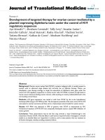
Figure 1 shows the model of a human leg moving on a
treadmill in the sagittal plane(X-Y plane). The Leg is mod-
eled as having two links – thigh, shank and two joints –
hip and knee. The foot is considered as a point mass at the
end of shank segment (i.e., at ankle joint). The swing
assistance device consists of two torsion springs – one at
the hip joint and the other at the knee joint. The stiffness
Journal of NeuroEngineering and Rehabilitation 2009, 6:24 />Page 3 of 13
(page number not for citation purposes)
constants c
1
, c
2
and the equilibrium configurations ,
of these springs are considered to be design parame-
ters.
The system dynamics depends on the following quanti-
ties: m
1
, m
2
– masses of the thigh and shank (leg + device);
L
1
, L
2
– lengths of thigh and shank segments; , –
location of the center of mass of the thigh and shank (leg
+ device) measured from their respective joints; I
1
, I
2
–
inertia of thigh and shank (leg + device) about their center
of mass. Please note that '(leg+ device)' indicates the
equivalent quantity based on human leg and device
parameters. Simulation results section shows how the
equivalent parameters are calculated based on anthropo-
metric data and device mass assumptions.
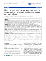
In our study, we have used two different models for the
hip motion: (i) hip is inertially fixed, (ii) hip has only ver-
tical motion, i.e., it is assumed to remain fixed in the hor-
izontal direction. While more complex models could have
been made to describe the human hip motion, we believe
that pendular motion of the hip in the sagittal plane may
be a reasonable first model. A spinal cord injury patient,
by himself or herself, has very little residual motion left in
the limbs and the sagittal plane motion will be the pre-
dominant motion during their treadmill training. In this
paper, we only describe the second model, where the hip
has only vertical motion (represented by red lines in Fig-
ure 1). We believe that this model is more realistic to cap-
ture the movement on a treadmill.
In this model, we assume that the foot of the stance leg
remains in contact with the treadmill and moves along
with it until the swing leg makes contact with the tread-
mill again. We also assume that the knee in the stance leg
remains locked. With these assumptions, using the kine-
matic model of the stance leg, we compute the up and
down motion of the hip. This motion is then used in the
dynamics of the swing leg.
Hip Motion
If the treadmill moves at a constant speed v, the position
of the contact point of the stance leg with the treadmill, Y
ft
at time t, is given as
where is the position of the contact point at the start
of the stance phase. Let x
t
be the position of treadmill in
the direction. Using kinematics, we write the vertical
position of the hip as
Hip angle during stance phase
θ
1s
is given as
Equations of Motion
Swing leg dynamics can be written using the Lagrange
equations.
where
τ
i
denotes the external torque applied at the joints.
The Lagrange function given in the above equation is
defined as
Where
θ
1
eq
θ
2
eq
L
c
1
L
c
2
yy vt
ft ft
=+
0
,
y
ft
0
ˆ
e
x
xt x L L vt y yh
ht ft
() ( ) ( ) ,=− + − + −
12
22
0
yt
h
() ( ).= 0 assumption
θ
1
1
s
y
ft
yh
x
t
x
h
=
−
−
⎛
⎝
⎜
⎜
⎞
⎠
⎟
⎟
−
tan .
d
dt
i
i
i
i
∂
∂
−
∂
∂
==
θ
θ
τ
,,.12
=−KE PE ,
KE m I m I
cm cm
=++ +
1
2
1
2
1
2
1
2
11
2
11
2
22
2
22
2
rr
ωω
Model schematicFigure 1
Model schematic. Model of a human leg in the sagittal plane
with hip moving as an inverted pendulum.
Journal of NeuroEngineering and Rehabilitation 2009, 6:24 />Page 4 of 13
(page number not for citation purposes)
In the above equation, and are unit vectors along
X and Y axes.
Note that while finding the device parameters from simu-
lations we assume that the external torque
τ
i
applied is
zero and based on the above dynamics we find
θ
i
(t).
Whereas while analyzing the experimental results, based
on the encoders data we know
θ
i
(t). We use this informa-
tion to calculate the external torque
τ
i
, more specifically
the human applied component. In the later case, external
torque
τ
i
can be treated as a summation of device interface
torques
τ
FT
(which is known as it is recorded by Force-
Torque (F/T) sensors) and the human applied torque
τ
h
.
Based on the dynamic equations we can estimate human
applied torque
τ
h
.
Knee Lock and Unlock
In human walking, the knee joint does not allow the
shank to move past
θ
2
= 0. This locking of the joint is an
instantaneous knee impact event. We account for the knee
locking and unlocking during our simulations. Once the
knee locks, the number of dynamic equations in (5)
changes from 2 to1. During the phase of locking, as typi-
cally done during modeling of impact, the angles are con-
sidered to be continuous while the rates have an
instantaneous jump. The new joint rate for the hip is com-
puted by angular momentum conservation about the hip
joint.
In the above equations '+' indicates quantities after impact
and '-' indicates before impact. H
O, leg
denotes the angular
momentum of the leg about the hip joint, L
c
denotes the
location of center of mass of the whole leg (assuming it is
straight, which it is after impact (knee locking)) from the
hip joint, m denotes the mass of the whole leg (m
1
+m
2
), I
denotes the moment of inertia of the whole leg about its
center of mass. Equating the angular momentum before
and after impact, we obtain from the knowledge of
θ
1
,
θ
2
, and . Please note that
ω
in Eq. (7) and in the
above equations refer to the same quantity. After locking,
the thigh and shank segments rotate about the hip joint as
a single link. Knee unlocks when the equation for reaction
torque at knee joint is not positive. Reaction torque is pos-
itive when knee is locked and does not exist(becomes
zero) when the knee unlocks. Hence, the equation for the
reaction torque has a zero crossing (value changes from
being positive to negative) at unlocking event. This condi-
tion is expressed as
In the above equation, the first term represents reaction
torue due to gravity, the second term represents reaction
torque due to torsion spring and the third represents reac-
tion torque due to shank acceleration. Based on day to day
observations of healthy subjects walking on a treadmill it
is observed that the knee does not unlock until the swing
leg touches the ground.
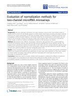
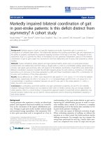
Design Optimization
The optimization of the design is schematically described
in Figure 2. Given the desired initial and final configura-
tions of the swing leg, the design parameters c
1
, c
2
, ,
are found from an optimization routine that gives a
feasible gait. During optimization, the system dynamic
equations were used to predict the gait. Inclusion of lock-
ing and unlocking (impact) events in dynamics would
introduce discontinuities in states and increase the time of
integration due to the inherent need to detect these
events. These would typically slow down the optimization
solution convergence. In order to speed up the integration
of dynamics, during optimization, knee locking was
approximated with an additional stiff spring that applies
torque only when the knee angle
θ
2
> 0. The use of stiff
spring simplified the numerical integration and helped
converge to a solution faster.
Error from the desired final configuration (not the entire
gait) was taken as the objective function that the optimi-
zation process would minimize. In addition, positive
ground clearance (the relative (vertical) position of the
foot w.r.t. the treadmill is greater than zero) at a finite
number of points during the gait was imposed as a con-
straint. The optimized parameters were then used to per-
form forward simulations of the leg. During these forward
simulations, locking event was not simplified with the
stiff spring but instead the exact model described in knee
lock and unlock section was used. Actual values of the
desired starting and final configurations are given in the
simulations results section.
PE m g c m g c
cm x eq cm x
( ) ( ) ( ) (=− ⋅+ − − ⋅+ −
11 11 1
2
22 22
1
2
1
2
re r e
θθ θ θ
22
2
eq
)
ree
11 1
11
cm h c x h c y
xL yL=+ ++[cos()][sin()]
θθ
re
211 12 11
22
cm h c x h c
xL L yL L=+ + + ++ +[ cos() cos( )] [ sin() sin(
θθθ θθθθ
12
+ )]e
y
ˆ
e
x
ˆ
e
y
Hmy xLmLImyL
Oleg h h c c h,
[cos() ] [(
−−−
=−++++
11 1
2
111 2 1
11
θθθ
LLxLL
mL L L L L
chc
ccc
22
22
11 1
21 1 1
)cos( ) ( )sin( )]
()( )
θθ
θ
−+
++ + +
−
22
2212
θθθ
−−−
⎡
⎣
⎤
⎦
++I ()
HmLy x mLI
Oleg c h h c,
[cos() sin()]
+++
=−++
θθθθ
11
2
11
θ
1
+
θ
1
−
θ
2
−
θ
−+−−+++mgL c mL x y L L
ceqchh21222 1 11
22
sin( ) ( sin( ) cos( ) (
θθ θ θ
cc
2
1
0
θ
)) ≤
θ
1
eq
θ
2
eq
Journal of NeuroEngineering and Rehabilitation 2009, 6:24 />Page 5 of 13
(page number not for citation purposes)
Simulation Results
Device parameters are found based on the following
healthy subject's biological data on whom the experimen-
tal tests were also conducted.
BodyWt = 72.6 kg
Height = 167 cm
Age = 35 yrs
L
thigh
= 0.41 m
L
shank
= 0.40 m
The following average anthropometric data for human leg
[23] was used to obtain the other important parameters
required for simulations.
m
thigh
= 0.1000 × Body Wt
m
shank
= 0.0465 × Body Wt
m
foot
= 0.0145 × Body Wt = foot mass
Design optimizationFigure 2
Design optimization. Schematic of device parameter optimization process used in the design of the swing assistive orthosis.
As a first step, System Dynamics are obtained for a particular model of Human leg motion. Using the dynamics, optimization is
carried out to find out device parameters. Error from desired final configuration is taken as objective function. Positive ground
clearance at discrete points is taken as a constraint. Comparision is made in simuations with and without passive device before
building the hardware.
Journal of NeuroEngineering and Rehabilitation 2009, 6:24 />Page 6 of 13
(page number not for citation purposes)
= 0.433 × L
thigh
(center of mass of thigh from hip
joint)
= 0.433 × L
shank
(center of mass of shank from hip
joint)
R
thigh
= 0.323 × L
thigh
(radius of gyration of thigh)
R
shank
= 0.302 × L
shank
(radius of gyration of shank)
Apart from the thigh and shank mass, in this simulation,
we also considered foot mass and device mass. We
assumed that the mass of the thigh and shank segments of
the deviceis 1 kg each and is distributed such that their
center of mass and radius of gyration coincide with center
of mass and radius of gyration of human thigh and shank
segments repectively. Based on the anthopometric data
and the device mass assumptions, the equivalent mass
and center of mass parameters to be used in the simula-
tion can be found as follows,
m
1
= m
thigh
+ m
device_thigh
m
2
= m
shank
+ m
foot
+ m
device_shank
L
1
= L
thigh
L
2
= L
shank
=
= ((m
shank
+ m
device_shank
) * + m
foot
* L
2
)/(m
2
)
The initial configuration of the swing leg was selected as
and the final
desired configuration
. These configura-
tions are chosen based on normal human gait data.
Desired swing time (t
des_swing
) was chosen as 0.7 s. As the
velocity of the hip joint at the beginning of swing phase is
related (equal) to the velocity of the hip joint at the end of
the stance phase, the intial velocity of hip joint can be cal-
culated as follows,
where, v is the treadmill velocity which can be calculated
from the kinematics and the desired swing time specifica-
tion as follows,
For the stance leg, we specify the symmetrically opposite
initial conditions, i.e., the final configuration of swing leg
is taken as the initial configuration of the stance leg and
vice versa. With these system parameters and desired con-
figurations, the optimization routine gives the design
parameters as c
1
= 7.9 Nm/rad, c
2
= 5.3 Nm/rad, =
22°, = 0°.
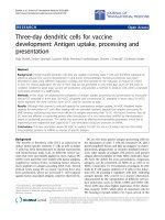
Using these optimized design parameters, we performed
one step and multistep simulations. Figure 3 shows the
stick diagrams of leg motion for one step simulation. The
red dotted line shows the motion of stance leg and the
blue solid line shows the motion of swing leg. The initial
position of swing leg is shown by a thick blue line with
diamond markers and the desired final position is shown
by a brown line with star markers. Figure 3(i) shows the
leg motion when the device is used with optimized design
parameters – swing leg has good ground clearance and
goes close to the desired final configuration. Figure 3(ii)
shows the leg motion when the design parameters are
kept constant but the leg mass is changed by 50% – even
in this case swing leg reaches goal point in a desirable
manner. The gait in these cases takes between 0.8 and 0.85
seconds to complete (which corresponds to a treadmill
speed of around 2 mph). These results show that the sys-
tem is robust to variations in leg mass.
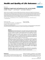
For a multi step simulation, we use the configuration of
leg from previous step as a initial configuration for the
next step. Figure 4 shows the joint trajectories of the swing
leg for a 100 step simulation. We see that the joint trajec-
tories are almost same during the 100 step simulation,
suggesting that the trajectory is stable and also robust to
changes in leg mass. In
θ
2
plots, we see that when
θ
2
reaches 0 degrees and stays at zero (i.e., the joint velocity
abruptly changes to zero). This is due to the knee locking
event. The joint velocity continues to be zero until the leg
touches the treadmill suggesting that the knee unlocking
event is not taking place.
Discussion
Our results from the simulation resulted in a more natural
human walking under the condition when the hip was
allowed to move up and down, compared to the case
when the hip remains inertially fixed. This is consistent
with human walking, where the hip moves up and down.
From the perspective of energy flow, the springs get
charged during the stance phase by the treadmill and the
body-weight support system which allows only a vertical
L
c
thigh
L
c
shank
L
c
1
L
c
thigh
L
c
2
L
c
shank
[, , , ][/. ,,,]
θθθθ π θ
10 10 20 20 1
6 022 0 0
=−
s
[, , , ][/. ,,,]
θθθ θ π θ
112 2 1
6 022 0 0
ffff s
=
θθ
θ
10 1
12 10
==
+
s
v
LL()cos()
;
v
LL
t
=
+( )sin( )
_
;
12 10
θ
des swing
θ
1
eq
θ
2
eq
Journal of NeuroEngineering and Rehabilitation 2009, 6:24 />Page 7 of 13
(page number not for citation purposes)
motion to the hip. In swing phase, the potential energy
stored in springs is converted to kinetic energy of the
swing leg. Some energy flows out at the hip, working
against the constraint of only vertical motion, and some
energy is lost during knee and heel impact. In human
walking, there is a finite-time when the leg is in double
support. In this phase, both swing and stance legs are in
contact with the ground. In future, if the foot is modeled
as a separate limb, this double support phase of human
walking can also be accounted.
Experimental Results and Discussion
Exoskeleton Design
Figure 5 shows an AutoCAD drawing of an exoskeleton
that was built using this design philosophy. This Auto-
CAD drawing lists the various components, including the
adjustable limb segments to accomodate a range of sub-
jects, the bracing attachments for the leg, the back support
system that allows the trunk to move up and down, the
force-torque sensors to compute the human applied joint
torques, and the swing assistive torsional springs at the
joints. Figure 6 shows the fabricated exoskeleton worn by
a healthy subject. The device has a belt that straps onto the
human trunk. Please note that this fabricated exoskeleton
does not support the weight of the human subject.
A pelvic link made of aluminum is attached rigidly to the
trunk belt. In order to help the pelvis remain nearly verti-
cal during treadmill walking, a back pack frame is used.
This back pack frame is rigidly connected to the pelvic link
through aluminum sections. Other links in the device are
the telescopic thigh and shank segments, connected suc-
cessively through revolute joints. All links have slots to
adjust the link lengths and match these to the human
wearing it. The device thigh is connected to the human
thigh with the help of a thigh brace. The device shank is
connected to the human foot via a foot piece. Currently,
the foot piece only allows sagittal plane ankle motion. At
the device hip and knee joints, torsion springs are con-
nected in parallel to obtain a desired stiffness and equilib-
rium configuration, suggested by the optimization.
Encoders are mounted at all revolute joints to measure hip
and knee angles. Two force-torque sensors are mounted
on each leg of the exoskeleton, one sandwiched between
the thigh link and the thigh brace and the other between
the shank link and the foot piece. These sensors measure
the forces and torques transmitted between the device and
the human.
Data Collection
The exoskeleton was first adjusted to match the limb
lengths of the subject, a 45 years healthy male of Asian ori-
gin, 70 inches tall. The subject's biological data was used
Simulation result with deviceFigure 3
Simulation result with device. Motion of stance leg and swing leg – (i) with assistive device and optimal parameters of the
torsional spring; (ii) With assistive device and optimal parameters of the torsional spring but with 50% change in leg mass.
Stance leg – red dotted line. Swing leg – blue solid line. Initial position of swing leg – thick blue line with diamond markers. Final
position of swing leg – brown line with star makers.
Journal of NeuroEngineering and Rehabilitation 2009, 6:24 />Page 8 of 13
(page number not for citation purposes)
to find the optimal spring parameters while walking on
the treadmill at a speed of around 2.0 mph (see simulation
results section). The appropriate springs were mounted on
the exoskeleton. Note that in a clinical setting too, based
on test subjects' biological data, device parameters can be
found from the simulations. Once the desired stiffness
parameters are obtained, the device joints' stiffness can be
approximately adjusted based on an existing collection of
springs. The equilibrium configurations of the springs can
then be suitably adjusted if the parts used to mount the
springs have slots or set of holes instead of a single hole
that would allow only a single equilibrium configuration.
In the current device, the encoder and force-torque sensor
data were collected using a dSpace 1103 system at 1000
Hz. The force-torque sensors were manufactured by ATI
and the encoders by USDigital. The subject walked on the
treadmill for 15 minutes with the exoskeleton to become
acclimated. Data was collected when a subject walked on
a treadmill at different speeds, ranging from 1.0 mph to
4.0 mph. Figure 7(a) shows the joint data,
θ
2
vs
θ
1
, of a
trial where the treadmill speed was 2 mph. Note that the
design was optimized for walking at a treadmill speed of
around 2.0 mph; hence, we show the results of this trial in
more detail. In this figure, multiple loops indicate multi-
ple steps during a trial. Red lines represent just the swing
phase, extracted from the full step data represented by
Joint trajectories for 100 step simulationFigure 4
Joint trajectories for 100 step simulation. Joint trajectories of swing leg for 100 step simulation with optimial parameters
of torsion spring – (i)
θ
1
vs time (ii)
θ
2
vs time. With 50% change in leg mass – (iii)
θ
1
vs time (iv)
θ
2
vs time
Device drawing in AutoCADFigure 5
Device drawing in AutoCAD. AutoCAD drawing of
Swing Assistance Device with Body Weight Support system
and treadmill – A. Torque Springs B. Straps C. Force Torque
Sensors at robot human interface D. Encoders at the Joints.
Journal of NeuroEngineering and Rehabilitation 2009, 6:24 />Page 9 of 13
(page number not for citation purposes)
both red and blue lines. Solid black line represents the
average swing data, computed by averaging over the mul-
tiple cycles. In order to perform averaging, we normalized
the step data to a fixed time length. The same data is plot-
ted against time in Figs. 7(b), (c). A 20 point moving aver-
age was used to smoothen the joint encoder data to
compute the joint velocity and acceleration, using central
difference scheme.
Data Interpretation
We analyzed the data using two methods to study the per-
formance differences with and without the spring assist:
(i) We estimated the joint torques applied by the human
during swing using the kinematic data obtained from the
joint encoders and the force-torque data obtained from
the interface force-torque sensors in conjunction with the
leg dynamics given in Sec. (ii) We estimated the human
applied joint torque using the dynamic model, where the
inputs to this model are the kinematics recorded by the
joint sensors. The second approach does not use the inter-
face force-torque data in the computations and hence rep-
resents the torque needed to excute the same trajectory as
in case (i) but without the spring assist. In an ideal situa-
tion, if the exoskeleton was working completely according
to the intended design, one would expect to see that the
joint torques in (i) are closer to zero, or much less com-
pared to those predicted in (ii). For the kinematic data
shown in Figure 7, the torques required by the human in
the two cases are shown in Figure 8. In these plots, solid
red lines correspond to (i), while the dotted blue lines to
(ii). Ideally, as we mentioned earlier, one would expect to
see the joint torques required by human to be smaller in
the device, since the device parameters were found based
on the assumption of zero-input from human. In Figure 8,
we see that the magnitude of the hip joint torque in (i) is
smaller – peak torques bounded by (≈5 Nm) compared to
(≈14.5 Nm) in (ii) – indicating that a subject with less
than normal muscle strength maybe able toper form this
gait while wearing the device. A similar comparison for
knee joint torque shows that the absolute torque with the
device is favorable during the early part of the swing but
becomes comparable to the magnitude of the torque with-
out it during the later part of the swing. These results indi-
cate that the exoskeleton performs favorably over the
swing at the designed treadmill speed, since it reduces the
magnitude of the hip and knee joint torque. However,
there is still room for improvement in performance of the
exoskeleton. These results are remarkable considering the
following observations:(i) the design is based on a sim-
plistic model of sagittal plane human walking,(ii)the
compliance of the human hip and knee joints were not
accounted in the dynamic model, (iii) the fabricated
device has inherent friction in the joints, which can be
reduced but never completely eliminated, (iv) the torque-
deflection curves of torsional springs used in the experi-
ment may not be completely linear.
Data for a Range of Treadmill Speeds
In order to evaluate the robustness of the design to varia-
tions in treadmill speed, the joint motion and interface
force-torque data was collected for a range of speeds
between 1.0 mph – 4.0 mph. Figure 9 shows the differ-
ence between the absolute magnitudes of torque required
in (ii) and (i), i.e., without and with the exoskeleton, for
treadmill speeds of 1 mph – 4 mph. This quantity is
labeled as (|
τ
h
| - |
τ
he
|) for the hip and (|
τ
k
| - |
τ
ke
|) for knee.
In these comparisons, the time scale was normalized over
different treadmill speeds to show the relative effects. In
these graphs, the positive area shows the regions of the
swing where the device is effective. The larger this area is,
more effective the device is at that speed. For the hip joint,
we see that the curve corresponding to2 mph treadmill
speed has the largest positive area and for the knee joint,
the curve with4 mph treadmill speed has the largest posi-
tive area. It is possible that further adjustments of the stiff-
ness of the torsion springs may improve the performance
even further. Figure 9 focussed on the magnitude of the
torque and their sign can be further investigated. For
Experimental setupFigure 6
Experimental setup. A healthy subject wearing the swing
assist exoskeleton while standing on a treadmill.
Journal of NeuroEngineering and Rehabilitation 2009, 6:24 />Page 10 of 13
(page number not for citation purposes)
Joint trajectories from an experimetal resultFigure 7
Joint trajectories from an experimetal result. (a) Hip versus Knee during a trial when treadmill speed was 2 mph. Red
lines represent swing phase extracted from full step data represented by red and blue lines combined. Solid black lines repre-
sent average swing phase. (b) Hip angle vs time (c) Knee angle vs time.
Joint torques corresponding to the experimental resultFigure 8
Joint torques corresponding to the experimental result. Estimate of torque applied by the subject at the hip and the
knee joints for a treadmill speed of 2.0 mph. Blue – with the exoskeleton, Red – without the exoskeleton.
Journal of NeuroEngineering and Rehabilitation 2009, 6:24 />Page 11 of 13
(page number not for citation purposes)
example, the torque in (i) may have the same or opposite
sign to (ii). The sign of the torque is more clearly
described in Figure 10, where the device effectiveness at
different treadmill speeds is compared in terms of sign but
not the magnitude. In these figures, a unit step signifies
that the device is effective in magnitude but torques in (i)
and (ii) have opposite signs. Two steps signify that the
device is effective both in magnitude and sign. The larger
the area under the curve, the higher the effectiveness of the
device at that treadmill speed. On comparison, we see that
for the hip, the 2.0 mph treadmill speed trial has the max-
imum area. The 3.0 and 4.0 mph speed trials also have
comparable areas, which shows the robustness of the
design over changes in the treadmill speed. For the knee
joint, for 1.0 mph, the area under the curve is very mini-
mal – indicating that the knee has poor performance. For
other treadmill speeds, the area under the curve is not as
small as that of 1.0 mph – indicating neither a good nor a
poor performance.
Conclusion
In this paper, we presented a simple un-motorized bilat-
eral exoskeleton for swing assistance and training of
motor impaired patients. This exoskeleton is aimed at
reducing the physical and financial costs associated with
therapist assisted training. The device consists of two seg-
ments – thigh and shank with torsion springs at hip and
knee joints. Stiffness of the springs and their equilibrium
configurations were the design parameters, which were
optimized based on the required performance of the
exoskeleton. We modeled the human leg with two links,
thigh and shank segments, moving in the sagittal plane.
The foot was modeled as a point mass and the hip had the
motion of an inverted pendulum. The dynamics are devel-
oped when the device is strapped to the leg. In the simu-
lation, we observed that the device helps the leg during
swing to clear the ground and go to a desired final config-
uration. We also performed simulations with change in
leg mass to evaluate the robustness of the design to varia-
tion of system parameters. We found that the system was
robust for up to 50% change in leg mass.
An exoskeleton was fabricated based on the optimized
parameters from simulations. This device was tested on a
healthy subject at different treadmill speeds. To show the
effectiveness of the device, we compare two different
cases. In case 1, we estimated the torque applied by the
human joints when walking with the device using the
joint kinematic data and interface force-torque sensors. In
case 2, we calculated the required torque to perform a sim-
ilar gait only using the kinematic data collected from joint
motion sensors. On analysis, we found that at 2.0 mph,
the device was effective in reducing the maximum hip
torque requirement and the knee joint during the begin-
ning of the swing. These behaviors were retained as the
treadmill speed was changed between 1–4 mph. These
Joint torques comparison with and without the deviceFigure 9
Joint torques comparison with and without the device. The difference in hip and knee joint torques without and with
the exoskeleton for treadmill speed variation between 1.0–4.0 mph. Higher the positive area under the curves, the exoskele-
ton is more effective at that treadmill speed.
Journal of NeuroEngineering and Rehabilitation 2009, 6:24 />Page 12 of 13
(page number not for citation purposes)
results were remarkable considering the simplicity of the
dynamic model, model uncertainty, non-ideal spring
behavior, and friction in the joints. We believe that the
results can be further improved in the future. Neverthe-
less, this promises to provide a useful and effective meth-
odolgy for design of un-motorized exoskeletons to assist
and train swing of motor-impaired patients.
Competing interests
Authors applied for a patent relating to the content of the
manuscript. University of Delaware holds the rights to the
patent.
Authors' contributions
KKM performed simulations and detailed exoskeleton
design. SKB helped in subject testing of the exoskeleton.
SKA provided overall guidance to the project including
conceptual design, dynamic simulations, and data inter-
pretation. All authors read and approved the final manu-
script.
Acknowledgements
We acknowledge the following sources of support for this work: NIH R24
and NIDRR Model Systems Center subcontracts from Rehabilitation Insti-
tute of Chicago, NIH National Center for Medical Rehabilitation Research
under Grant HD38582. We also acknowledge Vivek Sangwan for valuable
inputs.
Support of WCU (World Class University) program through the Korea Sci-
ence and Engineering Foundation funded by the Ministry of Education, Sci-
ence and Technology (No. R32-2008-000-10022-0) is also gratefully
acknowledged.
References
1. National Spinal Cord Injury Statistical Center: Annual Report. Bir-
mingham, AL 2005.
2. Barbeau H, Wainberg M, Finch L: Description and application of
a system for locomotor rehabilitation. Med Biol Eng Comput
1987, 25(3):341-344.
3. Behrman AL, J HS: Locomotor training after human spinal cord
injury: a series of case studies. Phys Ther 2000, 80(7):688-700.
4. Wernig A, Muller SL: Locomotion with body weight support
improved walking in persons with severe spinal cord injuries.
Paraplegia 1992, 30(4):229-238.
5. Barbeau H, Norman K, Fung J, Visintin M, Ladouceur M: Does neu-
rorehabilitation play a role in the recovery of walking in neu-
rological populations? Ann N Y Acad Sci 1998, 860:377-392.
6. Barbeau H, Fung J: The role of rehabilitation in the recovery of
walking in the neurological population. Curr Opin Neurol 2001,
14(6):735-740.
7. Dobkin B, Apple D, Barbeau H, Basso M, Behrman A, Deforge D:
Weight-supported treadmill vs over-ground training for
walking after acute incomplete SCI. Neurology 2006,
66(4):484-493.
8. Krebs HI, Hogan N: Robot-aided neurorehabilitation. IEEE Trans
Rehabil Eng 1998, 6:75-87.
9. Lum PS, Burgar CG, Shor PC, Majmundar M, Loos M Van Der:
Robot-assisted movement training compared with conven-
tional therapy techniques for the rehabilitation of upper
Device EffectivenessFigure 10
Device Effectiveness. Device effectiveness in terms of both 'sign' and 'magnitude' for different treadmill speeds at Hip and
Knee joints.
Publish with BioMed Central and every
scientist can read your work free of charge
"BioMed Central will be the most significant development for
disseminating the results of biomedical research in our lifetime."
Sir Paul Nurse, Cancer Research UK
Your research papers will be:
available free of charge to the entire biomedical community
peer reviewed and published immediately upon acceptance
cited in PubMed and archived on PubMed Central
yours — you keep the copyright
Submit your manuscript here:
/>BioMedcentral
Journal of NeuroEngineering and Rehabilitation 2009, 6:24 />Page 13 of 13
(page number not for citation purposes)
limb motor function following stroke. Arch Phys Med Rehabil
2002, 83:952.
10. Reinkensmeyer DJ, Kahn LE, Averbuch M, McKenna-Cole AN, Schmit
BD, Rymer WZ: Understanding and treating arm movement
impairment after chronic brain injury: Progress with the
arm guide. J Rehabil Res Dev. 2000, 37(6):653-662.
11. Rahman T, Ramanathan R, Stroud S, Sample W, Seliktar R, Harwin W,
Alexander M, Scavina M: Towards the control of a powered
orthosis for people with muscular dystrophy. Proceedings of the
Institution of Mechanical Engineers, Part H: Journal of Engineering in Med-
icine 2001, 215(3):267-274.
12. Agrawal SK, Gardener G, Pledgie S: Design and Fabrication of a
Gravity Balanced Planar Mechanism Using Auxiliary Paral-
lelograms. Journal of Mechanical Design, Transactions of the ASME
2001, 123(4):525-528.
13. Cardoso LF, Tomazio S, Herder JL: Conceptual design of a pas-
sive arm orthosis. Proceedings, ASME Design Engineering Technical
Conferences 2002.
14. Sanchez RJ, Liu J, Rao S, Shah P, Smith R, Rahman T, Cramer SC,
Bobrow JE, Reinkensmeyer DJ: Automating Arm Movement
Training Following Severe Stroke: Functional Exercises
With Quantitative Feedback in a Gravity-Reduced Environ-
ment. IEEE Transactions on Neural systems and Rehabilitation Engineer-
ing 2006, 14(3):378-389.
15. Colombo G, Joerg M, Schreier R, Dietz V: Treadmill training of
paraplegic patients using a robotic orthosis. J Rehabil Res Dev
2000, 37(6):693-700.
16. Banala S, Kulpe A, Agrawal SK: A Powered Leg Orthosis for Gait
Rehabilitation of Motor-Impaired Patients. Proceedings, IEEE
International Conference on Robotics and Automation 2007.
17. Banala S, Kim S, Agrawal SK, Scholz JP: Robot Assisted Gait Train-
ing with Active Leg Exoskeleton (ALEX). IEEE Trans Neural Syst
Rehabil Eng. 2009, 17(1):2-8.
18. Hornby TG, Zemon DH, Campbell D: Robotic-assisted, body-
weight-supported treadmill training in individuals following
motor incomplete spinal cord injury. Phys Ther 2005, 85:52-66.
19. Gottschall JS, Kram R:
Energy cost and muscular activity
required for leg swing during walking. J Appl Physiol. 2005,
99(1):20-23.
20. Banala S, Agrawal SK, Fattah A, Krishnamoorthy V, Hsu WL, Scholz
JP, Rudolph K: Gravity-Balancing Leg Orthosis and Its Per-
formance Evaluation. IEEE Transcation on Robotics 2006,
22(6):1228-1237.
21. Agrawal SK, Banala S, Fattah A, Sangwan V, Krishnamoorthy V, Hsu
WL, Scholz JP: Assessment of Motion of a Swing Legand Gait
Rehabilitation with a Gravity Balancing Exoskeleton. IEEE
Trans Neural Syst Rehabil Eng. 2007, 15(3):410-420.
22. Krishnamoorthy V, Hsu WL, Kesar TM, Benoit DL, Banala SK, Peru-
mal R, Sangwan V, Binder-Macleod S, Agrawal SK, Scholz JP: Gait
Training following stroke: A pilot study combining a gravity-
balanced orthosis device, functional electrical stimulation
and visual feedback. Journal of Neurologic Physical Therapy 2008,
232:102-202.
23. Winter DA: Biomechanics and Motor Control of Human Movement John
Wiley & Sons, Inc; 1990.