schaar, turaga, stockhammer - mpeg - 4 beyond conventional video coding
Bạn đang xem bản rút gọn của tài liệu. Xem và tải ngay bản đầy đủ của tài liệu tại đây (6.46 MB, 86 trang )
P1: IML/FFX P2: IML
MOBK011-FM Turaga MOBK011-Turaga.cls February 11, 2006 13:10
MPEG-4
Beyond Conventional
Video Coding
Object Coding, Resilience,
and Scalability
i
P1: IML/FFX P2: IML
MOBK011-FM Turaga MOBK011-Turaga.cls February 11, 2006 13:10
Copyright © 2006 by Morgan & Claypool
All rights reserved. No part of this publication may be reproduced, stored in a retrieval system, or
transmitted in any form or by any means—electronic, mechanical, photocopy, recording, or any other
except for brief quotations in printed reviews, without the prior permission of the publisher.
MPEG-4 Beyond Conventional Video Coding: Object Coding, Resilience, and Scalability
Mihaela van der Schaar, Deepak S Turaga and Thomas Stockhammer
www.morganclaypool.com
1598290428 paper van der Schaar/Turaga/Stockhammer
1598290436 ebook van der Schaar/Turaga/Stockhammer
DOI 10.2200/S00011ED1V01Y200508IVM004
A Publication in the Morgan & Claypool Publishers’ series
SYNTHESIS LECTURES ON IMAGE, VIDEO & MULTIMEDIA PROCESSING
Lecture #4
ISSN print: 1559-8136
ISSN online: 1559-8144
First Edition
10987654321
Printed in the United States of America
ii
P1: IML/FFX P2: IML
MOBK011-FM Turaga MOBK011-Turaga.cls February 11, 2006 13:10
MPEG-4
Beyond Conventional
Video Coding
Object Coding, Resilience,
and Scalability
Mihaela van der Schaar
University of California, Los Angeles
Deepak S Turaga
IBM T.J. Watson Research Center
Thomas Stockhammer
Munich University of Technology
SYNTHESIS LECTURES ON IMAGE, VIDEO & MULTIMEDIA
PROCESSING #4
M
&C
Morgan
&
Claypool Publishers
iii
P1: IML/FFX P2: IML
MOBK011-FM Turaga MOBK011-Turaga.cls February 11, 2006 13:10
iv
ABSTRACT
An important merit of the MPEG-4 video standard is that it not only provided tools and
algorithms for enhancing the compression efficiency of existing MPEG-2 and H.263
standards but also contributed key innovative solutions for new multimedia applications
such as real-time video streaming to PCs and cell phones over Internet and wireless
networks, interactive services, and multimedia access. Many of these solutions are cur-
rently used in practice or have been important stepping-stones for new standards and
technologies. In this book,we do not aim atproviding a complete reference for MPEG-4
video as many excellent references on the topic already exist. Instead, we focus on three
topics that we believe formed key innovations of MPEG-4 video and that will continue
to serve as an inspiration and basis for new, emerging standards, products, and technolo-
gies. The three topics highlighted in this book are object-based coding and scalability,
Fine Granularity Scalability, and error resilience tools. This book is aimed at engineering
students as well as professionals interested in learning about these MPEG-4 technolo-
gies for multimedia streaming and interaction. Finally, it is not aimed as a substitute or
manual for the MPEG-4 standard, but rather as a tutorial focused on the principles and
algorithms underlying it.
KEYWORDS
MPEG-4, object-coding, fine granular scalability, error resilience, robust transmission.
P1: IML/FFX P2: IML
MOBK011-FM Turaga MOBK011-Turaga.cls February 11, 2006 13:10
v
Contents
1. Introduction 1
2. Interactivity Support: Coding of Objects with Arbitrary Shapes 5
2.1 Shape Coding 8
2.1.1 Binary Shape Coding . 8
2.1.2 Grayscale Shape Coding 18
2.2 Texture Coding 20
2.2.1 Intracoding 20
2.2.2 Intercoding 22
2.3 Sprite Coding 24
2.4 Encoding Considerations 27
2.4.1 Shape Extraction/Segmentation 27
2.4.2 Shape Preprocessing 29
2.4.3 Mode Decisions 29
2.5 Summary 30
3. New Forms of Scalability in MPEG-4 33
3.1 Object-Based Scalability 33
3.2 Fine Granular Scalability 34
3.2.1 FGS Coding with Adaptive Quantization (AQ) 38
3.3 Hybrid Temporal-SNR Scalability with an all-FGS Structure 41
4. MPEG-4 Video Error Resilience 45
4.1 Introduction 45
4.2 MPEG-4 Video Transmission in Error-Prone Environment 46
4.2.1 Overview 46
4.2.2 Basic Principles in Error-Prone Video Transmission 48
4.3 Error Resilience Tools in MPEG-4 53
4.3.1 Introduction . . . 53
4.3.2 Resynchronization and Header Extension Code 53
4.3.3 Data Partitioning 56
P1: IML/FFX P2: IML
MOBK011-FM Turaga MOBK011-Turaga.cls February 11, 2006 13:10
vi CONTENTS
4.3.4 Reversible Variable Length Codes 57
4.3.5 Intrarefresh 59
4.3.6 New Prediction 61
4.4 Streaming Protocols for MPEG-4 Video—A Brief Review 63
4.4.1 Networks and Transport Protocols 63
4.4.2 MPEG-4 Video over IP 63
4.4.3 MPEG-4 Video over Wireless 66
5. MPEG-4 Deployment: Ongoing Efforts . 69
P1: IML/FFX P2: IML/FFX QC: IML/FFX T1: IML
MOBK011-01 Turaga MOBK011-Turaga.cls February 10, 2006 11:21
1
CHAPTER 1
Introduction
MPEG-4 (with a formal ISO/IEC designation ISO/IEC 14496) standardization was
initiated in 1994 to address the requirements of the rapidly converging telecommu-
nication, computer, and TV/film industries. MPEG-4 had a mandate to standardize
algorithms for audiovisual coding in multimedia applications, digital television, interac-
tive graphics, and interactive multimedia applications. The functionalities of MPEG-4
cover content-based interactivity, universal access, and compression, and a brief summary of
these is provided in Table 1.1. MPEG-4 was finalized in October 1998 and became an
international standard in the early months of 1999.
The technologies developed during MPEG-4 standardization, leading to its cur-
rent use especially in multimedia streaming systems and interactive applications, go sig-
nificantly beyond the pure compression efficiency paradigm [1] under which MPEG-1
and MPEG-2 were developed. MPEG-4 was the first major attempt within the re-
search community to examine object-based coding, i.e., decomposing a video scene into
multiple arbitrarily shaped objects, and coding these objects separately and efficiently.
This new approach enabled several additional functionalities such as region of interest
coding, adapting, adding or deleting objects in the scene, etc., besides also having the
potential to improve the coding efficiency. Furthermore, right from the outset, MPEG-4
was designed to enable universal access, covering a wide range of target bit-rates and re-
ceiver devices. Hence, an important aim of the standard was providing novel algorithms
for scalability and error resilience. In this book, we use MPEG-4
1
as the backdrop to
1
MPEG-4 has also additional components for combining audio and video with other rich media such
as text, still images, animation, and 2-D and 3-D graphics, as well as a scripting language for elaborate
P1: IML/FFX P2: IML/FFX QC: IML/FFX T1: IML
MOBK011-01 Turaga MOBK011-Turaga.cls February 10, 2006 11:21
2 MPEG-4 BEYOND CONVENTIONAL VIDEO CODING
TABLE 1.1: Functionalities Within MPEG-4
Content-based manipulation and bitstream
editing without transcoding
Hybrid natural and synthetic data coding
Improved temporal random access within
limited time frame and with fine resolution
Content-based interactivity
Robustness in error-prone environments
including both wired and wireless networks,
and high error conditions for low bit-rate video
Fine-granular scalability in terms of content,
quality, and complexity
Target bit rates between 5 and 64 kb·s for
mobile applications and up to 2 Mb/s for
TV/film applications.
Universal access
Improved coding efficiency
Coding of multiple concurrent data streams,
e.g., multiple views of video
Compression
describe the underlying principles and concepts behind some of these new technologies
that continue to have significant impact in video coding and transmission applications.
We first present algorithms for content-based interactivity, focusing on coding and
composition of objects with arbitrary shapes. We then describe technologies foruniversal
access, such as Object-based Scalability and Fine Granularity Scalability (FGS). Finally,
we discuss the use of MPEG-4 for multimedia streaming with a focus on error resilience.
programming. Recently, a new video coding standard within the MPEG-4 umbrella called MPEG-4 Part
10, which focuses primarily on compression efficiency, was also developed. Alternatively, in this book, we
do not consider these, and focus on the MPEG-4 part 2 video standard.
P1: IML/FFX P2: IML/FFX QC: IML/FFX T1: IML
MOBK011-01 Turaga MOBK011-Turaga.cls February 10, 2006 11:21
INTRODUCTION 3
We attempt to go beyond a simple description of what is included in the standard itself,
and describe multiple algorithms that were evaluated during the course of the standard
development. Furthermore, we also describe algorithms and techniques that lie outside
the scope of the standard, but enable some of the functionalities supported by MPEG-4
applications. Given the growing deployment of MPEG-4 in multimedia streaming sys-
tems, we include a standardset of experimentalresultsto highlighttheadvantages ofthese
flexibilities especially for multimedia transmission across different kinds of networks and
under varying streaming scenarios. Summarizing, this book is aimed at highlighting sev-
eral key points that we believe have had a major impact on the adoption of MPEG-4
into existing products, and serve as an inspiration and basis for new, emerging standards
and technologies. Additional information on MPEG-4, including a complete reference
text, may be obtained from [2–5].
This book is organized as follows. Chapter 2 covers the coding of objects with ar-
bitrary shape, including shape coding, texture coding, motion compensation techniques,
and sprite coding. We also include a brief overview of some nonnormative parts of the
standard such as segmentation, shape preprocessing, etc. Chapter 3 covers new forms
of scalability in MPEG-4, including object-based scalability and FGS. We also include
some discussion on hybrid forms of these scalabilities. In Chapter 4, we discuss the use
of MPEG-4 for multimedia streaming and access. We describe briefly some standard
error resilience and error concealment principles and highlight their use in the standard.
We also describe packetization schemes used for MPEG-4 video. We present results of
standard experiments that highlight the advantages of these various features for networks
with different characteristics. Finally, in Chapter 5, we briefly describe the adoption of
these technologies in applications and in the industry, and also ongoing efforts in the
community to drive further deployment of MPEG-4 systems.
P1: IML/FFX P2: IML/FFX QC: IML/FFX T1: IML
MOBK011-01 Turaga MOBK011-Turaga.cls February 10, 2006 11:21
4
P1: IML/FFX P2: IML/FFX QC: IML/FFX T1: IML
MOBK011-02 Turaga MOBK011-Turaga.cls February 10, 2006 11:21
5
CHAPTER 2
Interactivity Support:
Coding of Objects with
Arbitrary Shapes
In this section we describe the support within MPEG-4 for coding objects with arbitrary
shapes. In particular, there are three aspects that we focus on. We start by describing the
decomposition of a particular video frame intomultiple objects(with varying transparen-
cies), object planes, etc. We then describe the algorithms for coding the shape, followed
by algorithms to code the texture, including the use of motion compensation for such
arbitrarily shaped objects. Toward the end of this chapter we describe Sprite Coding,
an approach that encodes the background from multiple frames as one panoramic view
(sprite). Finally, we describe some encoding considerations and additional algorithms
that are not part of the MPEG-4 standard, but are required to enable object-based
coding.
MPEG-4 supports the coding of multiple Video Object Planes (VOPs) as images
of arbitrary shape
1
(corresponding to different objects) in order to achieve the desired
content-based functionalities. A set of VOPs, possibly with arbitrary shapes and posi-
tions, can be collected into a Group of VOPs (GOV), and several GOVs can be collected
into a Video Object Layer (VOL). A set of VOLs are collectively labeled a Video Object
1
The coding of standard rectangular image sequences is supported as a special case of the VOP approach.
P1: IML/FFX P2: IML/FFX QC: IML/FFX T1: IML
MOBK011-02 Turaga MOBK011-Turaga.cls February 10, 2006 11:21
6 MPEG-4 BEYOND CONVENTIONAL VIDEO CODING
VS0 VS1
VO0 VO1
GOV1
VOL1
GOV0
VOL
0
VOPn-1VOP0
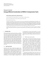
FIGURE 2.1: Object hierarchy within MPEG-4.
(VO), and sequence of VOs is termed a Visual object Sequence (VS). We show this
hierarchy in Fig. 2.1.
An example of VOPs, VOLs, and VOs is shown in Fig. 2.2. In the figure, there
are three VOPs, corresponding to the static background (VOP1), the tree (VOP2), and
the man (VOP3). VOL1 is created by grouping VOP1 and VOP2 together, while VOL2
includes only VOP3. Finally, these different VOLs are composed into one VO.
Each VO in the scene is encoded and transmitted independently, and all the
information required to identify each VO, and to help the compositor at the decoder
insert these different VOs into the scene, is included in the bitstream.
It is assumed that the video sequence is segmented into a number of arbitrarily
shaped VOPs containing particular content of interest, using online or offline segmenta-
tion techniques. As an illustration we show the segmented Akiyo sequence that consists
VOP1
VOL2
VOP2
VOP3
VOL1
VO
FIGURE 2.2: Video object planes, video object layers, and video objects.
P1: IML/FFX P2: IML/FFX QC: IML/FFX T1: IML
MOBK011-02 Turaga MOBK011-Turaga.cls February 10, 2006 11:21
INTERACTIVITY SUPPORT: CODING OF OBJECTS WITH ARBITRARY SHAPES 7
VOP1
foreground
VOP2
background
FIGURE 2.3: Segmented Akiyo sequence with binary alpha map indicating shape and position
of VOP1.
of a foreground object (VOP1) and a static background (VOP2) in Fig. 2.3. A binary
alpha map is also coded to indicate the shape and the location of VOP1.
The alpha map indicates which pixels belong to the VOP1 (in this case the news-
caster), and helps position it within the frame. MPEG-4 allows for overlapping and
nonoverlapping VOPs. In general, MPEG-4 allows VOPs to have varying levels of
transparency, and a grayscale alpha map (8 bit values with 0 representing completely
transparent and 255 representing completely opaque) is used to represent the pixels of
such VOPs. In Fig. 2.3 a binary alpha map is used to represent the pixels of VOP1 as it
is completely opaque, i.e., completely occludes the background.
MPEG-4 builds upon previously defined coding standards like MPEG-1/2 and
H.261/3 that use block-based coding schemes, and extends these to code VOPs with
arbitrary shapes. To use these block-based schemes for VOPs with varying locations,
sizes, and shapes, a shape-adaptive macroblock grid is employed. An example of an
MPEG-4 macroblock grid for the foreground VOP in the Akiyo sequence, obtained
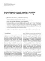
from [6], is shown in Fig. 2.4.
A rectangular window with size multiple of 16 (macroblock size) in each direction
is used to enclose the VOP and to specify the location of macroblocks within it. The
window is typically located in such a way that the top-most and the left-most pixels of
the VOP lie on the grid boundary. A shift parameter is coded to indicate the location of
P1: IML/FFX P2: IML/FFX QC: IML/FFX T1: IML
MOBK011-02 Turaga MOBK011-Turaga.cls February 10, 2006 11:21
8 MPEG-4 BEYOND CONVENTIONAL VIDEO CODING
MB completely
Standard
MB
Contour
Shift
Reference window
VOP window
outside object
Contour
MB
FIGURE 2.4: Shape adaptive macroblock grid for Akiyo foreground.
the VOP window with respect to the borders of a reference window (typically the image
borders).
The coding of a VOP involves adaptive shape coding and texture coding, both of
which may be performed with and without motion estimation and compensation. We
describe shape coding in Section 2.1 and texture coding in Section 2.2.
2.1 SHAPE CODING
Two types of shape coding are supported within MPEG-4, binary alpha map coding and
gray-scale alpha map coding. Binary shape coding is designed for opaque VOPs, while
grayscale alpha map coding is designed to account for VOPs with varying transparencies.
2.1.1 Binary Shape Coding
There are three broad classes of binary shape coding techniques. Block-based coding
and contour-based coding techniques code the shape explicitly, thereby encoding the
alpha map that describes the shape of the VOP. In contrast, chroma keying encodes the
shape of the VOP implicitly and does not require an alpha map. Different block-based
P1: IML/FFX P2: IML/FFX QC: IML/FFX T1: IML
MOBK011-02 Turaga MOBK011-Turaga.cls February 10, 2006 11:21
INTERACTIVITY SUPPORT: CODING OF OBJECTS WITH ARBITRARY SHAPES 9
and contour-based techniques were investigated within the MPEG-4 framework. These
techniques are described in the following sections.
2.1.1.1 Block-based shape coding
Block-based coding techniques encode the shape of the VOP block by block. The shape-
adaptive macroblock grid, shown in Fig. 2.4, is also superimposed on the alpha map,
and each macroblock on this grid is labeled as a Binary Alpha Block (BAB). The shape
is then encoded as a bitmap for each BAB. Within the bounding box, there are three
different kinds of BABs:
a) those that lie completely inside the VOP;
b) those that lie completely outside the VOP; and
c) those that lie at boundaries, called boundary or contour BABs.
The shape does not need to be explicitly coded for BABs that lie either completely
inside or completely outside the VOP, since these contain either all opaque (white) or
all transparent (black) pixels, and it is enough to signal this, using the BAB type. The
shape information needs to be explicitly encoded for boundary BABs, since these con-
tain some opaque and some transparent pixels. Two different block-based shape coding
techniques, context-based arithmetic encoding (CAE) and Modified Modified READ
(MMR) coding, were investigated in MPEG-4, and these are described in Sections
2.1.1.1 and 2.1.1.1.
Context-Based Arithmetic Encoding. For boundary BABs, a context-based shape
coder encodes the binary pixels in scan-line order (left to right and top to bottom)
and exploits spatial redundancy with the shape information during encoding. A tem-
plate of 10 causal pixels is used to define the context for predicting the shape value of the
current pixel. This template is shown in Fig. 2.5.
Since the template extends two pixels above, to the right and to the left of the
current pixel, some pixels of the BAB use context pixels from other BABs. When the
current pixel lies in the top two rows or left two columns, corresponding context pixels
P1: IML/FFX P2: IML/FFX QC: IML/FFX T1: IML
MOBK011-02 Turaga MOBK011-Turaga.cls February 10, 2006 11:21
10 MPEG-4 BEYOND CONVENTIONAL VIDEO CODING
C9
C8 C7
C2
C3
C4
C5
C6
C0
C1
X
X: Current pixel
C1 C9: Context pixels
FIGURE 2.5: Context pixels for intracoding of shape.
from the BABs to the top and left are used. When the current pixel lies in the two
right rows, context pixels outside the BAB are undefined, and are instead replaced by the
value of their closest neighbor from within the current BAB. A context-based arithmetic
coder is then used to encode the symbols. This arithmetic coder is trained on a previously
selected training data set.
Intercoding of shape information may be used to further exploit temporal redun-
dancies in VOP shapes. Two-dimensional (2-D) integer pixel shape motion vectors are
estimated using a full search. The best matching shape region in the previous frame
is determined by polygonal matching and is selected to minimize the prediction error
for the current BAB. This is analogous to the estimation of texture motion vectors and
is described in greater detail in Section 2.2.2. The shape motion vectors are encoded
predictively (using their neighbors as predictors) in a process similar to the encoding of
texture motion vectors. The motion vector coding overhead may be reduced by not esti-
mating separate shape motion vectors, instead reusing texture motion vectors for shape
information; however, this comes at the cost of worse prediction. Once the shape motion
vectors are determined, they are used to align a new template to determine the contexts
for the pixelbeing encoded. A context of nine pixels was defined for intercoding as shown
in Fig. 2.6.
C7
C2
C3
C4
C5
C0
C1
X
C8
C6
(mv
y
, mv
x
)
Current
frame
Previous
frame
X: Current pixel
C0 C3: Context pixels from current frame
C4 C8: Context pixels from previous frame
FIGURE 2.6: Context pixels for intercoding of shape.
P1: IML/FFX P2: IML/FFX QC: IML/FFX T1: IML
MOBK011-02 Turaga MOBK011-Turaga.cls February 10, 2006 11:21
INTERACTIVITY SUPPORT: CODING OF OBJECTS WITH ARBITRARY SHAPES 11
In addition to four causal spatial neighbors, four pixels from the previous frame, at
a location displaced by the corresponding shape motion vector (mv
y
, mv
x
), are also used
as contexts. The decoder may further decide not to encode any prediction residue bits,
and to reconstruct the VOP using only the shape information from previously decoded
versions of the VOP, and the corresponding shape motion vectors.
To increase coding efficiency further, the BABs may be subsampled by a factor of
2 or 4; i.e., the BAB may be coded as a subsampled 8 × 8 block or as a 4 × 4 block. The
subsampled blocks are then encoded using the techniques as above. This subsampling
factor is also transmitted to the decoder so that it can upsample the decoded blocks
appropriately. A higher subsampling factor leads to more efficient coding; however, this
also leads to losses in the shape information and could lead to blockiness in the decoded
shape. After experimental evaluations of subjective video quality, an adaptive nonlinear
upsampling filter was selected by MPEG-4 for recovering the shape information at the
decoder. The sampling grid for the pixels with both the subsampled pixel locations and
the original pixel locations is shown in Fig. 2.7. Also shown is the set of pixels that
are inputs (pixels at the subsampled locations) and outputs (reconstructed pixels at the
original locations) of the upsampling filter.
Since the orientation of the shape in the VOP may be arbitrary, it may be beneficial
to encode the shape top to bottom before left to right (for instance, when there are
more vertical edges than horizontal edges). Hence the MPEG-4 encoder is allowed to
transpose the BABs before encoding them. In summary, seven different modes may be
used to code each BAB and these are shown in Table 2.1. More details on CAE of BABs
may be obtained from [57].
Subsampled pixel
locations
Upsampled (original)
pixel locations
pixels used as inputs
by upsampling filter
Upsampled pixels created
as output of filter
FIGURE 2.7: Location of samples for shape upsampling.
P1: IML/FFX P2: IML/FFX QC: IML/FFX T1: IML
MOBK011-02 Turaga MOBK011-Turaga.cls February 10, 2006 11:21
12
TABLE 2.1: Different Coding Modes Within the CAE Scheme
BAB CODING DATA TO RASTER
TYPE MODE BE ENCODED SUBSAMPLING SCAN
Transparent
Completely
outside VOP
Intra/inter Indicated using the BAB
Type
Not used Not used
Opaque
Completely
inside VOP
Intra/inter Indicated using the BAB
Type
Not used Not used
Boundary Located
at VOP boundary
Intra The shape information is
explicitly coded using
intracontexts.
Factor of 1, 2, or 4
Inter Shape motion vectors are
predictively coded, and
shape information is coded
using spatiotemporal
contexts.
Factor of 1, 2, or 4
P1: IML/FFX P2: IML/FFX QC: IML/FFX T1: IML
MOBK011-02 Turaga MOBK011-Turaga.cls February 10, 2006 11:21
13
Inter without
shape mvs
Texture motion vectors are
reused, and shape
information is coded using
spatiotemporal contexts.
Factor of 1, 2, or 4
Inter without
prediction error
Shape motion vectors are
predictively coded, and no
prediction error is coded.
Not used Not used
Inter without
prediction error
and shape mvs
Texture motion vectors are
reused, and no prediction
error is coded.
Not used Not used
More details on CAE schemes may be obtained from [7–9].
P1: IML/FFX P2: IML/FFX QC: IML/FFX T1: IML
MOBK011-02 Turaga MOBK011-Turaga.cls February 10, 2006 11:21
14 MPEG-4 BEYOND CONVENTIONAL VIDEO CODING
Reference line
Current line
Chan
g
in
g
pixel
FIGURE 2.8: MMR coding used in the FAX standard.
Modified Modified READ (MMR) Shape Coding. In this shape coding technique
[10], the BAB is directly encoded as a bitmap, using an MMR code (developed for
the Fax standard). MMR coding encodes the binary data line by line. For each line of
the data, it is necessary only to encode the positions of changing pixels (where the data
change from black to white or vice versa). The positions of the changing pixels on the
current line are then encoded relative to the positions of changing pixels on a reference
line, chosen to be directly above the current line. An example of this is shown in Fig. 2.8.
After the current line is encoded, it may be used as a reference line for future lines.
Like for the CAE scheme, BABs are coded differently on the basis of whether they are
transparent, opaque, or boundary BABs. Only the type is used to indicate transparent
and opaque BABs, while MMR codes are used for boundary BABs. In addition, motion
compensation may be used to capture the temporal variation of shape, with full search
used to determine the binary shape motion vectors, and the residual signal coded using
the MMR codes. Each BAB may also be subsampled by a factor of 2 or 4, and this needs
to be indicated to the decoder. Finally, the scan order may be vertical or horizontal based
on the shape of the VOP.
2.1.1.2 Contour-Based Shape Coding
In contrast with block-based coding techniques, contour-based techniques encode the
contour describing the shape of the VOP boundary. Two different contour-based tech-
niques were investigated within the MPEG-4 framework, and these included vertex-
based shape coding and baseline-based shape coding.
Vertex-Based Shape Coding. In vertex-based shape coding [11], the outline of the
shape is represented using a polygonal approximation. A key component of vertex-based
shape coding involves selecting appropriate vertices for the polygon. The placement
P1: IML/FFX P2: IML/FFX QC: IML/FFX T1: IML
MOBK011-02 Turaga MOBK011-Turaga.cls February 10, 2006 11:21
INTERACTIVITY SUPPORT: CODING OF OBJECTS WITH ARBITRARY SHAPES 15
Vertex 1
Vertex 2
Vertex 3
Polygonal Approximation Step n
Polygonal Approximation Step n+1
Polygonal Approximation Step n+2
Vertex 4
Vertex 5
New vertex is added at point where shape distortion greater than threshold
FIGURE2.9: Iterative shape approximation using polygons. Wherever the error exceeds the threshold,
a new vertex is inserted.
of the vertices of the polygon controls the local variation in the shape approximation
error. A common approach to vertex placement is as follows. The first two vertices are
placed at the two ends of the main axis of the shape (the polygon in this case is a line).
For each side of the polygon it is checked whether the shape approximation error lies
within a predefined tolerance threshold. If the error exceeds the threshold, a new vertex
is introduced at the point with the largest error, and the process is repeated for the newly
generated sides of the polygon. This process is shown, for the shape map of the Akiyo
foreground VOP, in Fig. 2.9.
Once the polygon is determined, only the positions of the vertices need to be
transmitted to the decoder. In case lossless encoding of the shape is desired, each pixel
on the shape boundary is labeled a vertex of the polygon. Chain coding [12, 13] is then
used to encode the positions of these vertices efficiently. The shape is represented as a
chain of vertices, using either a four-connected set of neighbors or an eight-connected
set of neighbors. Each direction (spaced at 90
◦
for the four-connected case or at 45
◦
for
the eight-connected case) is assigned a number, and the shape is described by a sequence
of numbers corresponding to the traversing of these vertices in a clockwise manner. An
example of this is shown in Fig. 2.10.
To further increase the coding efficiency, the chain may be differentially encoded,
where the new local direction is computed relative to the previous local direction, i.e., by
P1: IML/FFX P2: IML/FFX QC: IML/FFX T1: IML
MOBK011-02 Turaga MOBK011-Turaga.cls February 10, 2006 11:21
16 MPEG-4 BEYOND CONVENTIONAL VIDEO CODING
−3
−3,−3,4,4,−1,−2,−2,0,2
−3,0,−1,0,3,−1,0,2,2,−1
−2,−1,0,4,−1,0,1,0,2,−1
1,−1,−2,−2,2,1,1,2,2,4,3
4
3
2
Direct chain code:
Differential chain code:
Starting point
1
0
−2
−1
Four neighbors Eight neighbors
FIGURE 2.10: Chain coding with four- and eight-neighbor connectedness.
rotatingthe definition vectorsso that0correspondstothe previous localdirection.Finally,
to capture the temporal shape variations, a motion vector can be assigned to each vertex.
Baseline-Based Shape Coding. Baseline-based shape coding [10] also encodes the
contour describing the shape. The shape is placed onto a 2-D coordinate space with the
X-axis corresponding to the main axis of the shape. The shape contour is then sampled
clockwise and the y-coordinates of the shape boundary pixels are encoded differentially.
Clearly, thex-coordinates of thesecontour pixelseither decrease or increase continuously,
and contourpixels where thedirection changes are labeled turning points. Thelocation of
these turning points needs to be indicated to the decoder. An example of baseline-based
coding for a contour is shown in Fig. 2.11.
In thefigure, fourdifferentturning pointsareindicated, corresponding towhen the
X-coordinates of neighboring contour pixels change between continuously increasing,
remaining the same, or continuously decreasing.
2.1.1.3 Chroma Key Shape Coding
Chroma key shape coding [14] was inspired from the blue-screen technique used by film
and TV studios. Unlike the other schemes described, this is an implicit shaped coding
technique. Pixels that lie outside the VOP are assigned a color, called a chroma key, not
present in the VOP (typically a saturated color) and the resulting sequence of frames
is encoded using a standard MPEG-4 coder. The chroma key is also indicated to the
P1: IML/FFX P2: IML/FFX QC: IML/FFX T1: IML
MOBK011-02 Turaga MOBK011-Turaga.cls February 10, 2006 11:21
INTERACTIVITY SUPPORT: CODING OF OBJECTS WITH ARBITRARY SHAPES 17
Startin
g
point
Y coordinates: −
Differential values: −2, 1, 0, 1, 1, 1, 0, −1, 0, −1, −1, 0
Turning point
X-axis
Y-axis
1
2
−1
−2
0
2, −1, −1, 0, 1, 2, 2, 1, 1, 0, −1, −1
FIGURE 2.11: Baseline-based shape coding.
decoder where decoded pixels with color corresponding to the chroma-key are viewed
as transparent. An important advantage of this scheme is the low computational and
algorithmic complexity for the encoder and decoder. For simple objects like head and
shoulders, chroma keying provides very good subjective quality. However, since the shape
information is carried by the typically subsampled chroma components, this technique
is not suitable for lossless shape coding.
2.1.1.4 Comparison of Different Shape Coding Techniques
During MPEG-4 Standardization, these different shape coding techniques were evalu-
atedthoroughly interms oftheircodingefficiency,subjective quality withlossyshapecod-
ing, hardware and software complexity, and their performance in scalable shape coders.
Chroma keying was not included in the comparison as it is not as efficient as the other
shape coding techniques, and the decoded shape topology was not stable, especially for
complex objects. Furthermore, due to quantization and losses, the color of the key often
bleeds into the object.
All the other shape coding schemes meet the requirements of the standard by
providing, lossless, subjectively lossless and lossy shape coding. Furthermore, all these
algorithms may be extended to allow scalable shape coding, bitstream editing, shape
only decoding, and have support for low delay applications, as well as applications using
error-prone channels.
P1: IML/FFX P2: IML/FFX QC: IML/FFX T1: IML
MOBK011-02 Turaga MOBK011-Turaga.cls February 10, 2006 11:21
18 MPEG-4 BEYOND CONVENTIONAL VIDEO CODING
The evaluation of the shape coders was performed in two stages. In the first
stage, the contour-basedschemes were compared against each other, and the block-based
coding schemes were compared against each other, to determine the best contour-based
shape coder, and the best block-based shape coder. In the second stage, the best contour-
based coder wascompared against thebest block-based coder todetermine the best shape
coding scheme.
Among contour-based coding schemes, it was found that the vertex-based shape
coder outperformed the baseline coder both in terms of coding efficiency for intercoding
and in terms of computational complexity. Among the block-based coding schemes, the
CAE coder outperformed theMMR coder for both intra-and intercoding of shape (both
lossless and lossy). Hence, in the second stage, the vertex-based coder and the CAE were
compared to determine the best shape coding technique. The results of this comparison,
obtained from [7], are included in Table 2.2.
After the above-detailed comparison, the CAE was determined to have better
performance
2
than the vertex-based coder and was selected to be part of the standard.
2.1.2 Grayscale Shape Coding
Grayscale alpha map coding is used to code the shape and transparency of VOPs in the
scene. Unlike in binary shape coding, where all the blocks completely inside the VOP are
opaque, in grayscale alpha map coding, different blocks of the VOP may have different
transparencies. There are two different cases of grayscale alpha map coding.
2.1.2.1 VOPs with Constant Transparency
In this case, grayscale alpha map coding degenerates to binary shape coding; however,
in addition to the binary shape, the 8 bit alpha value corresponding to the transparency
of the VOP also needs to be transmitted. In some cases, the alpha map near the VOP
boundary is filtered to blend the VOP into the scene. Different filters may be applied to
a strip of width up to three pixels inside the VOP boundary, to allow this blending. In
such cases, the filter coefficients also need to be transmitted to the decoder.
2
Recent experiments have shown that chain coding performed on a block-by-block basis performs compa-
rably with CAE for intracoding.
P1: IML/FFX P2: IML/FFX QC: IML/FFX T1: IML
MOBK011-02 Turaga MOBK011-Turaga.cls February 10, 2006 11:21
INTERACTIVITY SUPPORT: CODING OF OBJECTS WITH ARBITRARY SHAPES 19
TABLE 2.2: Comparison Between CAE and Vertex-Based Shape Coding
CAE VERTEX BASED
Coding efficiency:
Intra Lossless
7.8% lower data rate
Coding efficiency:
Inter Lossless
20.5% lower data rate
Coding efficiency:
Inter Lossy
Better at small distortions Better at large distortions
Scalability overhead
for three layers (layer
three lossless)
30–50% of lossless one layer
rate for predictive coding
No optimized results for
inter coding
Delay Slightly lower
Hardware
implementation
complexity
Decoding on chip without
access to external memory
Huffman decoder smaller
than arithmetic decoder,
however, required random
access to external memory
Software
implementation
complexity
No optimized coder was available; however, the
nonoptimized code had similar performance for both
algorithms
2.1.2.2 VOPs with Varying Transparency
For VOPs with arbitrary transparencies, the shape coding is performed in two steps.
First the outline of the shape is encoded using binary shape coding techniques. In the
second step, the alpha map values are viewed as luminance values and are coded using
padding, motion compensation, and DCT. More details on padding are included in
Section 2.2.1.1.