PLC s7 300 SM331 manual
Bạn đang xem bản rút gọn của tài liệu. Xem và tải ngay bản đầy đủ của tài liệu tại đây (458.59 KB, 25 trang )
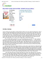
Analog modules
6.6 Analog input module SM 331; AI 8 x 13 Bit; (6ES7331-1KF02-0AB0)
S7-300 Module data
Manual, 08/2009, A5E00105505-06
297
6.6 Analog input module SM 331; AI 8 x 13 Bit; (6ES7331-1KF02-0AB0)
Order number
6ES7331-1KF02-0AB0
Properties
● 8 inputs in 8 channel groups
● Programmable resolution at each channel group (12 bits + sign)
● Programmable measurement type per channel group:
– Voltage
– Current
– Resistance
– Temperature
● Any measuring range per channel
● Motor protection / temperature monitoring with PTC in accordance with IEC 60034-11-2
type A
● Temperatures detected via KTY83/110, KTY84/130 silicon temperature sensors
Terminal assignment
The diagrams below show various wiring options. These examples apply to all channels
(channel 0 to 7).
Note
When connecting voltage and current transducers, make sure that the maximum permitted
common-mode voltage C
MV
of 2 V is not exceeded between the inputs. Prevent measuring
errors by interconnecting the corresponding M- terminals.
Analog modules
6.6 Analog input module SM 331; AI 8 x 13 Bit; (6ES7331-1KF02-0AB0)
S7-300 Module data
298 Manual, 08/2009, A5E00105505-06
Wiring: Voltage measurement
8
,
6ದ
0
0ದ
8
,
6ದ
0
0ದ
8
,
6ದ
0
0ದ
8
,
6ದ
0
0ದ
&+
&+
&+
&+
8
,
6ದ
0
0ದ
8
,
6ದ
0
0ದ
8
,
6ದ
0
0ದ
8
,
6ದ
0
0ದ
0
&+
&+
&+
&+
9
9
0
8
/
0
5HI
① Voltage measurement (± 5 V, ±10 V, 1 V to 5 V, 0 V to 10 V)
② Voltage measurement (± 50 mV, ± 500 mV, ± 1 V) (note the input resistance defined in the technical data)
③ Equipotential bonding
④ Internal supply
⑤ + 5 V from backplane bus
⑥ Logic and backplane bus interface
⑦ Electrical isolation
⑧ Multiplexer
⑨ Analog digital converter (ADC)
⑩ Current source
Figure 6-10 Block diagram and terminal diagram
Analog modules
6.6 Analog input module SM 331; AI 8 x 13 Bit; (6ES7331-1KF02-0AB0)
S7-300 Module data
Manual, 08/2009, A5E00105505-06
299
Wiring: 2-wire and 4-wire transducers for current measurement
/
0
/
0
'08
8
,
6ದ
0
0ದ
8
,
6ದ
0
0ದ
8
,
6ದ
0
0ದ
8
,
6ದ
0
0ದ
&+
&+
&+
&+
8
,
6ದ
0
0ದ
8
,
6ದ
0
0ದ
8
,
6ದ
0
0ದ
8
,
6ದ
0
0ದ
&+
&+
&+
&+
'08
① 4-wire transducer (0/4 mA to 20 mA or ± 20 mA)
② 2-wire transducer (4 mA to 20 mA)
③ Equipotential bonding
④ Internal supply
⑤ + 5 V from backplane bus
⑥ Logic and backplane bus interface
⑦ Electrical isolation
⑧ Multiplexer
⑨ Analog to Digital Converter (ADC)
⑩ Current source
Figure 6-11 Block diagram and terminal diagram
Analog modules
6.6 Analog input module SM 331; AI 8 x 13 Bit; (6ES7331-1KF02-0AB0)
S7-300 Module data
300 Manual, 08/2009, A5E00105505-06
Wiring: Resistance measurement with 2-, 3- and 4-wire connection
The following connection possibilities also apply to silicon temperature sensors and PTCs.
8
,
6ದ
0
0ದ
8
,
6ದ
0
0ದ
8
,
6ದ
0
0ದ
8
,
6ದ
0
0ದ
&+
&+
&+
&+
8
,
6ದ
0
0ದ
8
,
6ದ
0
0ದ
8
,
6ದ
0
0ದ
8
,
6ದ
0
0ದ
&+
&+
&+
&+
① 2-wire connection. Insert a bridge between M and S (no line resistance compensation).
② 3-wire connection
③ 4-wire connection. The fourth line may not be wired (remains unused)
④ 4-wire connection. The fourth line is routed to the terminal strip in the cabinet but is not wired.
⑤ Internal supply
⑥ + 5 V from backplane bus
⑦ Logic and backplane bus interface
⑧ Electrical isolation
⑨ Multiplexer
⑩ Analog to Digital Converter (ADC)
⑪ Current source
Figure 6-12 Block diagram and terminal diagram
Note
It is not necessary to interconnect the M- terminals when measuring using resistors,
resistance thermometers, PTCs, or silicon temperature sensors. However, interconnection of
the M- terminals may enhance interference immunity.
Analog modules
6.6 Analog input module SM 331; AI 8 x 13 Bit; (6ES7331-1KF02-0AB0)
S7-300 Module data
Manual, 08/2009, A5E00105505-06
301
Technical specifications
Technical specifications
Dimensions and weight
Dimensions W x H x D (mm) 40 x 125 x 117
Weight ca. 250 g
Module-specific data
Supports isochronous mode no
Number of inputs
with resistive transducers
8
8
Cable length
shielded
max. 200 m
max. 50 m at 50 mV
Voltages, currents, electrical potentials
Constant current for resistive transducers
Resistance thermometer and resistance measurements 0 Ω
to 600 Ω
Resistance measurement 0 to 6 kΩ, PTC,
silicon temperature sensors
0.83 mA (pulsed)
0.25 mA (pulsed)
Electrical isolation
between channels and the backplane bus
between channels
yes
no
Maximum potential difference
between inputs (CMV)
Between the inputs and M
internal
(V
iso
)
2.0 VDC
75 VDC / 60 VAC
Isolation test voltage 500 VDC
Current consumption
from the backplane bus
max. 90 mA
Power loss of the module typ. 0.4 W
Generation of analog values
Measuring principle Integrating
Integration/conversion time/resolution (per channel)
programmable
yes
Interference frequency suppression at interference frequency
f1 in Hz
50 60
Integration time in ms
60 50
Basic conversion time, including the integration time in ms
66 55
Additional conversion time for resistance measurements in ms 66 55
Resolution in bits (including overshoot range)
13 bits 13 bits
Interference frequency suppression, error limits
Interference frequency suppression at f = n (f1 ± 1 %), (f1 = interference frequency) n=1.2
Common mode interference (V
CM
< 2 V)
Seriesmode interference (peak value < rated input range)
> 86 dB
> 40 dB
Analog modules
6.6 Analog input module SM 331; AI 8 x 13 Bit; (6ES7331-1KF02-0AB0)
S7-300 Module data
302 Manual, 08/2009, A5E00105505-06
Technical specifications
Crosstalk between inputs > 50 dB
Operational limit (across entire temperature range, relative tofull-scale value in the input range)
± 0.6%
Voltage input
± 5 V
± 10 V
1 V to 5 V
0 V to 10 V
± 50 mV
± 500 mV
±1 V
± 0.5%
Current input
± 20 mA
0 mA to 20 mA
4 mA to 20 mA
± 0.5%
Resistor/PTC
0 kΩ to 6 kΩ
0 Ω to 600 Ω
PTC
± 0.5%
± 0.5%
± 0.5%
Pt 100
Ni 100
Standard
± 1.2 K
Pt 100
Ni 100
Klima
± 1 K
Ni 1000,
LG-Ni 1000
Standard
± 1 K
Ni 1000
LG-Ni 1000
Klima
± 1 K
Resistance thermometer/silicon temperature sensors
KTY83/110
KTY84/130
± 3.5 K
± 4.5 K
Basic error limit (operational limit at 25 °C, relative tofull-scale value in the input range)
± 0.4%
Voltage input
± 5 V
± 10 V
1 V to 5 V
0 V to 10 V
± 50 mV
± 500 mV
±1 V
± 0.3%
Current input
± 20 mA
0 mA to 20 mA
4 mA to 20 mA
± 0.3%
Resistor/PTC
0 kΩ to 6 kΩ
0 Ω to 600 Ω
PTC
± 0.3%
± 0.3%
± 0.3%
Analog modules
6.6 Analog input module SM 331; AI 8 x 13 Bit; (6ES7331-1KF02-0AB0)
S7-300 Module data
Manual, 08/2009, A5E00105505-06
303
Technical specifications
Pt 100
Ni 100
Standard
± 1 K
Pt 100
Ni 100
Klima
± 0.8 K
Ni 1000
LG-Ni 1000
Standard
± 0.8 K
Ni 1000
LG-Ni
1000 Klima
± 0.8 K
Resistance thermometer/silicon temperature sensors
KTY83/110
KTY84/130
± 2 K
± 2.7 K
Temperature error (relative to input range) ± 0.006 %/K / 0.006 K/K
Linearity error (relative to input range) ± 0.1 % / 0.1 K
Repeat accuracy (in transient state at 25 °C, relative to input
range)
± 0.1 % / ± 0.1 K
Status, interrupts, diagnostics
Interrupts none
Diagnostic functions none
Sensor selection data
Input ranges (rated values) / input impedance
Voltage
± 50 mV
± 500 mV
± 1 V
± 5 V
± 10 V
1 V to 5 V
0 V to 10 V
100 kΩ
Current
± 20 mA
0 mA to 20 mA
4 mA to 20 mA
100 Ω
Resistor/PTC
0 kΩ to 6 kΩ
0 Ω to 600 Ω
PTC
100 MΩ
Analog modules
6.6 Analog input module SM 331; AI 8 x 13 Bit; (6ES7331-1KF02-0AB0)
S7-300 Module data
304 Manual, 08/2009, A5E00105505-06
Technical specifications
Resistance thermometer/silicon temperature sensors
Pt 100
Ni 100
Ni 1000
LG-Ni
1000
Standard / Klima
KTY83/110
KTY84/130
100 MΩ
Maximum voltage at voltage input U+ (destruction limit) max. 30 V, continuous
Maximum voltage at voltage inputs M+, M-, S- (destruction limit) max. 12 V continuous; 30 V for a duration of max. 1 s
Maximum current at current input I+ (destruction limit) 40 mA
Wiring of the signal sensors using a 40pin front connector
for voltage measurement
for current measurement
– as 2-wire transducer
– as 4-wire transducer
supported
supported, with external supply
supported
for resistance measurement
with 2-wire connection
with 3-wire connection
with 4-wire connection
supported
supported
supported
Characteristics linearization programmable
for resistance thermometers
Pt 100 Standard / Klima
Ni 100 Standard / Klima
Ni 1000 Standard / Klima
LG-Ni 1000 Standard / Klima
Technical unit of temperature measurement
Degrees Centigrade, degrees Fahrenheit, Kelvin
Analog modules
6.6 Analog input module SM 331; AI 8 x 13 Bit; (6ES7331-1KF02-0AB0)
S7-300 Module data
Manual, 08/2009, A5E00105505-06
305
6.6.1 Measurement types and ranges
Introduction
The measurement type and range is configured at the "measuring range" parameter in
STEP 7
.
Selected type of measurement Measuring range
Voltage
V:
± 50 mV
± 500 mV
± 1 V
± 5 V
1 V to 5 V
0 V to 10 V
± 10 V
Current I 0 mA to 20 mA
4 mA to 20 mA
± 20 mA
resistance (4-wire connection)
R-4L
6 kΩ
600 Ω
PTC
Thermal resistance
RTD-4L (linear, 4-wire connection)
(temperature measurement)
Silicon temperature sensors
Pt 100 Klima / Standard
Ni 100 Klima / Standard
Ni 1000 Klima / Standard
LG-Ni 1000 Klima / Standard
KTY83/110
KTY84/130
Analog modules
6.6 Analog input module SM 331; AI 8 x 13 Bit; (6ES7331-1KF02-0AB0)
S7-300 Module data
306 Manual, 08/2009, A5E00105505-06
6.6.2 Programmable parameters
Introduction
You will find a description of the general procedure for assigning parameters to analog
modules in section Programming analog modules (Page 251).
Parameters
Table 6- 17 Overview of the parameters of SM 331; AI 8 x 13 Bit
Parameters Range of values Default Parameter
type
Scope
Measurement
Measurement type
disabled
Voltage V
Current I
Resistance R, PTC
Thermal resistance RTD,
silicon temperature sensors
V
Voltage
± 50 mV; ± 500 mV; ±1 V;
1 V to 5 V
± 5 V; 0 V to 10 V; ± 10 V
± 10 V
Current
0 mA to 20 mA; 4 mA to 20 mA; ± 20 mA
± 20 mA
Resistance
0 Ω to 600 Ω; 0 kΩ to 6 kΩ; PTC
600 Ω
Measuring range
Thermoelectric resistance (linear)
Pt 100 Klima / Standard
Ni 100 Klima / Standard
Ni 1000 Klima / Standard
LG-Ni 1000 Klima / Standard
KTY83/110
KTY84/130
Pt 100
Standard
Temperature coefficient
Pt 100
0.003850 Ω/Ω/ °C (IST-90)
Ni 100 / Ni 1000
0.006180 Ω/Ω/ °C
LG-Ni 1000
0.005000 Ω/Ω/ °C
0.003850
Channel
Interference frequency
suppression
50 Hz; 60 Hz 50 Hz
Temperature unit
Degrees Centigrade, degrees Fahrenheit,
Kelvin*
degrees
Centigrade
dynamic
Module
* only Pt 100 Standard, Ni 100 Standard, Ni 1000 Standard, LG-Ni 1000 Standard
Analog modules
6.6 Analog input module SM 331; AI 8 x 13 Bit; (6ES7331-1KF02-0AB0)
S7-300 Module data
Manual, 08/2009, A5E00105505-06
307
6.6.3 Additional information on SM 331; AI 8 x 13 Bit
Using the module
The spare parts of the SM 331-1KF02 are compatible with the SM 331-1KF01 and are
configured with HSP 2067. HSP 2067 can be installed for STEP7 V5.4, SP5 and higher and
is included for STEP7 V5.4, SP6 and higher.
Unused channels
Set the "disabled" value at the "measurement type" parameter for unused channels. This
setting reduces module cycle times.
Interconnect the M- terminals of unused channels.
Using PTC resistors
PTCs are suitable for monitoring the temperature of or providing thermal protection for
complex drives and transformer windings. The module has no analog values when PTC
resistances are used. Status information on fixed temperature ranges are displyed instead of
analog values.
● When setting the parameters, select measurement type R "Resistance" and measuring
range "PTC".
● Connect the PTC (see "Terminal diagram for resistance measurement").
● Use PTC resistors that comply with IEC 60034-11-2 (previously, PTC thermistors that
complied with DIN/VDE 0660, Part 302).
● Sensor data for the PTC resistor:
Property Technical
specifications
Comment
Response to rising temperature
< 550 Ω Normal range:
Bit 0 = "0", bit 2 = "0" (in the PII)
550 Ω to 1650 Ω Advance warning range:
Bit 0 = "0", bit 2 = "1" (in the PII)
> 1650 Ω Actuating range:
Bit 0 = "1", bit 2 = "0" (in the PII)
Response to falling temperature
> 750 Ω Actuating range:
Bit 0 = "1", bit 2 = "0" (in the PII)
750 Ω to 540 Ω Advance warning range:
Bit 0 = "0", bit 2 = "1" (in the PII)
Switching points
< 540 Ω Normal range:
Bit 0 = "0", bit 2 = "0" (in the PII)
(RRT-5) °C
(RRT+5) °C
(RRT+15) °C
Measurement
voltage
Voltage at PTC
Max. 550 Ω
Min. 1,330 Ω
Min. 4,000 Ω
Max. 7.5 V
RRT = Rated response temperature
Analog modules
6.6 Analog input module SM 331; AI 8 x 13 Bit; (6ES7331-1KF02-0AB0)
S7-300 Module data
308 Manual, 08/2009, A5E00105505-06
● Assignment in the process image input (PII)
0HDVXUHGUHVLVWDQFH5HVSRQVHWKUHVKROGEHWZHHQSUHZDUQLQJWKUHVKROG
DQGUHVSRQVHYDOXH
0HDVXUHGUHVLVWDQFH!5HVSRQVHWKUHVKROG
(%[
(%[
[ ,QSXWDGGUHVVRIWKHPRGXOH෪FKDQQHOQXPEHU
● Notes on programming
NOTICE
Only bits 0 and 2 in the process image input are relevant for evaluation. You can use
bits 0 and 2 to monitor the temperature of a motor, for example.
Bits 0 and 2 in the process image input cannot be saved. When assigning parameters,
make sure that the motor, for example, starts up in a controlled manner (by means of an
acknowledgment).
Bits 0 and 2 can never be set at the same time; they are set one after the other.
Using silicon temperature sensors
Silicon temperature sensors are commonly used to detect temperatures in motors.
● When assigning the parameters, select measurement type "thermoresistor" and
measuring range "KTY83/110" or "KTY84/130".
● Connect the temperature sensor (see "Terminal diagram for resistance measurement").
Use temperature sensors which comply with the Product Specifications published by
Philips Semiconductors.
● KTY83 series (KTY83/110)
● KTY84 series (KTY84/130)
Also take note of the accuracy of the temperature sensors.
The temperature is specified in 0.1 degrees C, 0.1 degrees K, and/or 0.1 degrees F, see
section Representation of the analog values of analog input channels (Page 220).
Analog modules
6.7 Analog input module SM 331; AI 8 x 12 bit; (6ES7 331-7KF02-0AB0)
S7-300 Module data
Manual, 08/2009, A5E00105505-06
309
6.7 Analog input module SM 331; AI 8 x 12 bit; (6ES7 331-7KF02-0AB0)
Order number
6ES7331-7KF02-0AB0
Properties
● 8 inputs in 4 channel groups
● Programmable measurement type at each channel group
– Voltage
– Current
– Resistance
– Temperature
● Programmable resolution at each channel group (9/12/14 bits + sign)
● Any measuring range selection per channel group
● Programmable diagnostics and diagnostic interrupt
● Programmable limit value monitoring for 2 channels
● Programmable hardware interrupt when limit is exceeded
● Electrically isolated to CPU and load voltage (not for 2-wire transducers)
Resolution
The measured value resolution is directly proportional to the selected integration time, that
is, the measured value resolution increases in proportion to length of the integration time at
the analog input channel.
Diagnostics
For information on diagnostics messages consolidated in the "group diagnostics" parameter,
refer to the table
Diagnostic messages of analog input modules
.
Hardware interrupts
Hardware interrupts for channel groups 0 and 1 can be programmed in
STEP 7
. However,
set a hardware interrupt only for the first channel of a channel group, that is, either at
channel 0, or at channel 2
Terminal assignment
The diagrams below show various wiring options The input impedance depends on the
setting of the measuring range module, see table
Measurement types and ranges
.
Analog modules
6.7 Analog input module SM 331; AI 8 x 12 bit; (6ES7 331-7KF02-0AB0)
S7-300 Module data
310 Manual, 08/2009, A5E00105505-06
Wiring: Voltage measurement
9
9
9
9
9
9
9
7
6)
&+
&+
&+
&+
&+
&+
&+
&+
&RPS
'&
9
9
/
0
0
ದ
0
ದ
0
0
0
ದ
0
$1$
0
0
0
ದ
0
ದ
0
0
0
ದ
0
ದ
0
0
0
)X
QF
WLRQDO
JURXQG
%DFNSODQHEXV
LQWHUIDFH
(OHFWULFDO
LVRODWLRQ
,QWHUQDO
VXSSO\
&XUUHQW
VRXUFH
,QW
FRPS
1RQH
0XOWLSOH
[HU
0HDVXULQJ
UDQJHPRGXOHV
$'&
([WFRPSHQVDWLRQ
(TXLSRWHQWLDO
ERQGLQJ
Figure 6-13 Block diagram and wiring diagram
Measuring range module settings
Measuring range Measuring range module setting
± 80 mV
± 250 mV
± 500 mV
± 1,000 mV
A
± 2.5 V
± 5 V
1 V to 5 V
± 10 V
B
Analog modules
6.7 Analog input module SM 331; AI 8 x 12 bit; (6ES7 331-7KF02-0AB0)
S7-300 Module data
Manual, 08/2009, A5E00105505-06
311
Wiring: 2-wire and 4-wire transducers for current measurement
9
7
6)
&+
&+
&+
&+
&+
&+
&+
&+
'&
/
/
0
0
ದ
0
ದ
0
0
0
ದ
0
$1$
0
ದ
0
0
0
ದ
0
ದ
0
0
0
ದ
&20
3
0
ದ
0
0
0
0
0
0
/
/
/
)XQFWLRQDO
JURXQG
%DFNSODQHEXV
LQWHUIDFH
(OHFWULFDO
LVRODWLRQ
,QWHUQDO
VXSSO\
&XUUHQW
VRXUFH
,QW
FRPS
1RQH
0XOWLSOH
[HU
0HDVXULQJ
UDQJHPRGXOHV
$'&
([WFRPSHQVDWLRQ
(TXLSRWHQWLDO
ERQGLQJ
ZLUHWUDQVGXFHU
ZLUHWUDQVGXFHU
Figure 6-14 Block diagram and wiring diagram
Note
The interconnection between M
ANA
and M- (terminals 11, 13, 15, 17, 19) is not required when
using grounded 4-wire transducers with non-isolated supply.
Measuring range module settings
Measuring range Measuring range module setting
2-wire transducer 4 mA to 20 mA D
4-wire transducer ± 3.2 mA
± 10 mA
0 mA to 20 mA
4 mA to 20 mA
± 20 mA
C
CAUTION
Any voltage measurement will destroy the measuring range module if "current" measuring
mode is set.
Analog modules
6.7 Analog input module SM 331; AI 8 x 12 bit; (6ES7 331-7KF02-0AB0)
S7-300 Module data
312 Manual, 08/2009, A5E00105505-06
Wiring: 2-, 3- and 4-wire connection of resistance transducers or thermoresistors
9
7
6)
&+
&+
&+
&+
&+
&+
&+
&+
'&
/
0
,
&
ದ
0
ದ
0
,
&
,
&
ದ
&RPS0
$1$
0
ದ
0
,
&
,
&
ದ
0
0
,
&
,
&
ದ
&RP
S
0
ದ
0
,
&
)XQF
WLRQDO
JURXQG
%DFNSODQHEXV
LQWHUIDFH
(OHFWULFDO
LVRODWLRQ
,QWHUQDO
VXSSO\
&XUUHQW
VRXUFH
,QW
FRPS
1RQH
0XOWLSOH
[HU
0HDVXULQJ
UDQJHPRGXOHV
$'&
([WFRPSHQVDWLRQ
(TXLSRWHQWLDO
ERQGLQJ
① 4-wire connection
② 3-wire connection
③ 2-wire connection
Figure 6-15 Block diagram and terminal diagram
Measuring range module settings
Measuring range Measuring range module
setting
150 Ω
300 Ω
600 Ω
A
Thermoresistor
(linear, 4-wire connection) (temperature
measurement)
RTD-4L
Pt 100 Klima
Ni 100 Klima
Pt 100 Standard
Ni 100 Standard
A
Note
"Resistance measurement" is only available at one channel per group. The "2nd" channel
of the group is used accordingly for current measuring mode (I
C
). The "1st" channel of the
group returns the measured value. The "2nd" channel of the group is assigned the default
overflow value "7FFF
H
."
There is no compensation for power resistors for "2- and 3-wire connections".
Analog modules
6.7 Analog input module SM 331; AI 8 x 12 bit; (6ES7 331-7KF02-0AB0)
S7-300 Module data
Manual, 08/2009, A5E00105505-06
313
Wiring: Thermocouples with external compensation
Insert a bridge between Comp+ and M
ANA
when using the internal compensation.
9
7
6)
&+
&+
&+
&+
&+
&+
&+
&+
&RPS
&203
'&
/
0
0
ದ
0
ದ
0
0
0
ದ
0
$1$
0
0
0
ದ
0
ದ
0
0
0
ದ
0
ದ
0
0
0
)
X
QF
WLRQDO
JURXQG
%DFNSODQHEXV
LQWHUIDFH
(OHFWULFDO
LVRODWLRQ
,QWHUQDO
VXSSO\
&XUUHQW
VRXUFH
,QW
FRPS
1RQH
0XOWLSOH
[HU
0HDVXULQJ
UDQJHPRGXOHV
$'&
([WFRPSHQVDWLRQ
(TXLSRWHQWLDO
ERQGLQJ
Figure 6-16 Block diagram and wiring diagram
Measuring range module settings
Measuring range Measuring range module setting
Thermocouple TC-I
(internal comparison) (thermal
voltage measurement)
Linearization is ignored
Thermocouple TC-E
(external comparison)
(thermovoltage measurement)
Linearization is ignored
Type N [NiCrSi-NiSi]
Type E [NiCr-CuNi]
Type J [Fe-CuNi]
Type K [NiCr-Ni]
Type L [Fe-CuNi]
A
Thermocouple
(linear, internal comparison)
(temperature measurement) TC-
IL
Thermocouple
(linear, external comparison)
(temperature measurement) TC-
EL
Type N [NiCrSi-NiSi]
Type E [NiCr-CuNi]
Type J [Fe-CuNi]
Type K [NiCr-Ni]
Type L [Fe-CuNi]
A
Analog modules
6.7 Analog input module SM 331; AI 8 x 12 bit; (6ES7 331-7KF02-0AB0)
S7-300 Module data
314 Manual, 08/2009, A5E00105505-06
Note
An interconnection of M- and M
ANA
is prohibited when using grounded thermocouples. In
this case, you must ensure that low-resistance equipotential bonding is in place so that
the permitted common-mode voltage is not exceeded.
Interconnect M- and M
ANA
when using non-grounded thermocouples
Technical specifications
Technical specifications
Dimensions and weight
Dimensions W x H x D (mm) 40 x 125 x 117
Weight ca. 250 g
Module-specific data
Supports isochronous mode no
Number of inputs
with resistive transducers
8
4
Cable length
shielded
max. 200 m
max. 50 m at 80 mV and with thermocouples
Voltages, currents, electrical potentials
Rated electronics supply voltage L +
Reverse polarity protection
24 VDC
yes
Transducer power supply
Supply current
short circuit-proof
max. 60 mA (per channel)
yes
Constant current for resistive transducers typ. 1.67 mA (pulsed)
Electrical isolation
between channels and the backplane bus
between channels and electronics power supply
– Not for 2-wire transducers
Yes
Yes
Maximum potential difference
Between inputs and M
ANA
(CMV)
– at signal = 0 V
between inputs (CMV)
between M
ANA
and M
internal
(V
iso
)
typ. DC 2.5 V (> DC 2.3V)
typ. DC 2.5 V (> DC 2.3V)
75 VDC / 60 VAC
Isolation test voltage 500 VDC
Current consumption
from the backplane bus
from load voltage L+
max. 50 mA
max. 30 mA (without 2-wire transducer)
Power loss of the module typ. 1 W
Analog modules
6.7 Analog input module SM 331; AI 8 x 12 bit; (6ES7 331-7KF02-0AB0)
S7-300 Module data
Manual, 08/2009, A5E00105505-06
315
Technical specifications
Generation of analog values
Measuring principle Integrating
Integration/conversion time/resolution (per channel)
Programmable
Yes
Integration time in ms
2.5 16
2
/
3
20 100
Basic conversion time, including the integration time in ms
3 17 22 102
Additional conversion time for resistance measurement, in ms
or
1 1 1 1
additional conversion time for wire-break monitoring in ms
or
10 10 10 10
additional conversion time for resistance measurements and
wire-break monitoring in ms
16 16 16 16
Resolution in bits (including overrange)
9 bits 12 bits 12 bits 14 bits
Interference frequency suppression at interference
frequency f1 in Hz
400 60 50 10
Basic execution time of the module in ms (all channels
enabled)
24 136 176 816
Measured value smoothing none
Interference frequency suppression, error limits
Interference frequency suppression at F = n (f1 ± 1 %), (f1 = interference frequency)
Common mode interference (V
CM
< 2.5 V)
Seriesmode interference (peak value < rated input range)
> 70 dB
> 40 dB
Crosstalk between inputs > 50 dB
Operational limit (across entire temperature range, relative tofull-scale value in the input range)
Voltage input
80 mV
250 mV to 1,000 mV
2.5 V to 10 V
± 1%
± 0.6%
± 0.8%
Current input
3.2 mA to 20 mA ± 0.7%
Resistance
150 Ω; 300 Ω; 600 Ω ± 0.7%
Thermocouple
Types E, N, J, K, L ± 1.1%
Resistance thermometer
Pt 100/Ni 100 ± 0.7%
Pt 100 climatic ± 0.8%
Basic error limit (operational limit at 25 °C, relative tofull-scale value in the input range)
Voltage input
80 mV
250 mV to 1,000 mV
2.5 V to 10 V
± 0.7%
± 0.4%
± 0.6%
Current input
3.2 mA to 20 mA ± 0.5%
Resistance
150 Ω; 300 Ω; 600 Ω ± 0.5%
Thermocouple
Types E, N, J, K, L ± 0.7%
Resistance thermometer
Pt 100/Ni 100 ± 0.5%
Pt 100 climatic ± 0.6%
Analog modules
6.7 Analog input module SM 331; AI 8 x 12 bit; (6ES7 331-7KF02-0AB0)
S7-300 Module data
316 Manual, 08/2009, A5E00105505-06
Technical specifications
Temperature error (relative to input range) ± 0.005%/K
Linearity error (relative to input range) ± 0.05%
Repeat accuracy (in settled state at 25 °C, relative to input
range)
± 0.05%
Temperature error of internal compensation ± 1%
Status, interrupts, diagnostics
Interrupts
Limit interrupt
Diagnostic interrupt
programmable
Channels 0 and 2
programmable
Diagnostic functions
Group error display
Reading diagnostics information
programmable
red LED (SF)
supported
Sensor selection data
Input ranges (rated values) / input impedance
Voltage
± 80 mV
± 250 mV
± 500 mV
± 1000 mV
± 2.5 V
± 5 V
1 V to 5 V
± 10 V
10 MΩ
10 MΩ
10 MΩ
10 MΩ
/100 kΩ
100 kΩ
100 kΩ
100 kΩ
Current
± 3.2 mA
± 10 mA
± 20 mA
0 mA to 20 mA
4 mA to 20 mA
25 Ω
25 Ω
25 Ω
25 Ω
25 Ω
Resistance
150 Ω
300 Ω
600 Ω
10 MΩ
10 MΩ
10 MΩ
Thermocouples
Types E, N, J, K, L 10 MΩ
Resistance thermometers
Pt 100, Ni 100 10 MΩ
Maximum voltage at voltage input (destruction limit) max. 20 V, continuous
75 V for the duration of max. 1 s (duty factor 1:20)
Maximum current at current input (destruction limit) 40 mA
Wiring of the signal sensors using a 20-pin front connector
for voltage measurement
supported
for current measurement
as 2-wire transducer
as 4-wire transducer
supported
supported
For thermoresistor/resistance measurement
with 2-wire connection
Supported, cable resistances are not compensated
Analog modules
6.7 Analog input module SM 331; AI 8 x 12 bit; (6ES7 331-7KF02-0AB0)
S7-300 Module data
Manual, 08/2009, A5E00105505-06
317
Technical specifications
with 3-wire connection Supported, cable resistances are not compensated
with 4-wire connection Supported, cable resistances are compensated
Load of the 2-wire transducer
max. 820 Ω
Characteristics linearization
for thermocouples
programmable
Types E, N, J, K, L
for resistance thermometers
Pt 100 (Standard and Klima range)
Ni 100 (Standard and Klima range)
Temperature compensation
Internal temperature compensation
programmable
supported
External temperature compensation with compensating
box
supported
Compensation for 0 °C reference junction temperature
supported
Technical unit of temperature measurement
degrees Centigrade
Analog modules
6.7 Analog input module SM 331; AI 8 x 12 bit; (6ES7 331-7KF02-0AB0)
S7-300 Module data
318 Manual, 08/2009, A5E00105505-06
6.7.1 Measurement types and ranges
Introduction
Module SM 331; AI 8 x 12 Bit has measuring range modules
The measurement type and range is configured at the "measuring range" parameter in
STEP
7
.
The default setting of the module is "voltage" measurement with "± 10V" range. You can use
these default settings without having to program the SM 331; AI 8 x 12 Bit in
STEP 7
.
Measuring range modules
You may have to change the position of the measuring range modules to suit the
measurement type and range (see the chapter
Setting the measuring types and ranges of
analog input channels
). The necessary settings are also available on the module's imprint.
Mark the position of the measuring range module on the front door (see figure).
5DQJH
$%
&'
Measurement types and ranges
Table 6- 18 Measurement types and ranges
Selected type of measurement Measuring range
(type of sensor)
Measuring range module
settings
± 80 mV
± 250 mV
± 500 mV
± 1000 mV
A
Voltage
V
± 2.5 V
± 5 V
1 V to 5 V
± 10 V
B
Thermocouple
TC-I
(internal comparison) (thermal voltage
measurement)
Linearization is ignored
Thermocouple
TC-E
(external comparison) (thermovoltage
measurement)
Linearization is ignored
Type N [NiCrSi-NiSi]
Type E [NiCr-CuNi]
Type J [Fe-CuNi]
Type K [NiCr-Ni]
Type L [Fe-CuNi]
A
Thermocouple
(linear, internal comparison)
(temperature measurement) TC-IL
Type N [NiCrSi-NiSi]
Type E [NiCr-CuNi]
A
Analog modules
6.7 Analog input module SM 331; AI 8 x 12 bit; (6ES7 331-7KF02-0AB0)
S7-300 Module data
Manual, 08/2009, A5E00105505-06
319
Selected type of measurement Measuring range
(type of sensor)
Measuring range module
settings
Thermocouple
(linear, external comparison)
(temperature measurement) TC-EL
Type J [Fe-CuNi]
Type K [NiCr-Ni]
Type L [Fe-CuNi]
Current (2-wire transducer)
2DMU
4 mA to 20 mA D
Current (4-wire transducer)
4DMU
± 3.2 mA
± 10 mA
0 mA to 20 mA
4 mA to 20 mA
± 20 mA
C
Resistance (4-wire connection)
R-4L
150 Ω
300 Ω
600 Ω
A
Thermoresistor
(linear, 4-wire connection) (temperature
measurement)
RTD-4L
Pt 100 Klima
Ni 100 Klima
Pt 100 Standard
Ni 100 Standard
A
Channel groups
The channels of SM 331; AI 8 x 12 Bit are arranged in four groups of two channels. You can
assign parameters only to one channel group.
SM 331; AI 8 x 12 Bit is equipped with one measuring range module per channel group.
The table below shows the relevant configuration of channel groups. The channel group
number is required to program SFC parameters in the user program.
Table 6- 19 Assignment of SM 331; AI 8x12 bit channels to channel groups
Channels form one channel group each
Channel 0
Channel 1
Channel group 0
Channel 2
Channel 3
Channel group 1
Channel 4
Channel 5
Channel group 2
Channel 6
Channel 7
Channel group 3
See also
Programming analog modules (Page 251)
Diagnostics messages of analog input modules (Page 253)
Analog modules
6.7 Analog input module SM 331; AI 8 x 12 bit; (6ES7 331-7KF02-0AB0)
S7-300 Module data
320 Manual, 08/2009, A5E00105505-06
6.7.2 Programmable parameters
Introduction
For information on programming analog modules, refer to the chapter
Programming analog
modules
.
Parameters
Table 6- 20 Overview of the parameters for SM 331; AI 8 x 12 Bit
Parameters Range of values Default Parameter
type
Scope
Enable
Diagnostics interrupt
Process interrupt when
limit exceeded
yes/no
yes/no
no
no
dynamic
Module
Process interrupt trigger
High limit
Low limit
May be restricted by the measuring range
from 32511 to - 32512
from - 32512 to 32511
-
dynamic
Channel
Diagnostics
Group diagnostics
with line continuity check
yes/no
yes/no
no
no
static
Channel
group
Measurement
Measurement type
disabled
Voltage V
4DMU current (4-wire transducer)
2DMU current (2-wire transducer)
R-4L resistance (4-wire connection)
RTD-4L thermoresistor
(linear, 4-wire connection)
TC-I thermocouple
(internal comparison)
TC-E thermocouple
(external comparison)
TC-IL thermocouple
(internal comparison)
TC-EL thermocouple
(linear, external comparison)
V
Measuring range
See the table
Measurement types and
ranges
± 10 V
Noise suppression
400 Hz; 60 Hz; 50 Hz; 10 Hz 50 Hz
dynamic
Channel or
channel
group
Analog modules
6.7 Analog input module SM 331; AI 8 x 12 bit; (6ES7 331-7KF02-0AB0)
S7-300 Module data
Manual, 08/2009, A5E00105505-06
321
6.7.3 Additional information on SM 331; AI 8 x 12 Bit
Unused channels
As certain programmed inputs may remain unused due to the channel group configuration,
make allowances for the special features of these inputs outlined below in order to be able to
use the diagnostics functions at these used channels:
● Voltage measurement (except 1 V to 5V) and for thermocouples: Short-circuit unused
channels and connect these with M
ANA
. This optimizes interference immunity of the
analog input module. Set the "disabled" value at the "measurement type" parameter for
unused channels. This setting reduces module cycle times. Also short-circuit the COMP
input if this is not used.
● Measuring range 1 V to 5 V: wire the used and unused inputs of the same channel group
in parallel.
● Current measurement, 2-wire transducer: There are two options of wiring the channel
circuit.
a) Open unused input; channel group diagnostics disabled. If you were to enable
diagnostics, the analog module would trigger a single diagnostic interrupt, and light up its
SF LED.
b) Loading the unused input using a 1.5 kΩ to 3.3 kΩ resistor. This allows you to enable
diagnostics for this channel group.
● Current measurement 4 mA to 20 mA, 4-wire transducer: wire the unused inputs of the
same channel group in series.
All channels deactivated
If you disable all input channels of the module and enable diagnostics at the parameters of
SM 331; AI 8 x 12 Bit, the module does not report "external auxiliary voltage missing."
Line continuity check for the 4 mA to 20 mA measuring range
If you configured a measuring range of 4 mA to 20 mA, and enabled the line continuity
check, the analog input module logs a wire-break event to diagnostics data when the current
drops below 3,6 mA.
The module also triggers a diagnostics interrupt if this function is enabled in the program.
A wire break can only be signaled by means of the lit SF LED and the diagnostic bytes must
be evaluated in the user program if diagnostics interrupts are disabled.
If you configured a measuring range of 4 mA to 20 mA, disabled the line continuity check,
and enabled diagnostic interrupts, the module triggers a diagnostic interrupt when the
underflow value is reached.
Line continuity check
The line continuity check is designed only for temperature measurements (thermocouples
and thermoresistors.)
See also
Representation of the analog values of analog input channels (Page 220)