Toyota camry 2006 2011 mirror hệ thống kính trên toyota camry đời 2006 2011
Bạn đang xem bản rút gọn của tài liệu. Xem và tải ngay bản đầy đủ của tài liệu tại đây (1.25 MB, 24 trang )
MIRROR – POWER MIRROR CONTROL SYSTEM
MI–1
MI
BODYMIRROR
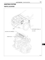
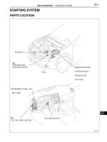
POWER MIRROR CONTROL SYSTEM
PARTS LOCATION
OUTER MIRROR SWITCH
OUTER REAR VIEW MIRROR
OUTER REAR VIEW MIRROR
(INSTRUMENT PANEL J/B)
MAIN BODY ECU
- A/C NO. 2 FUSE
- ECU-ACC FUSE
ENGINE ROOM R/B, J/B
- RR DEF RELAY
- RR DEF FUSE
- ECU-IG FUSE
B137068E01
MI–2
MIRROR – POWER MIRROR CONTROL SYSTEM
MI
SYSTEM DIAGRAM
Outer Mirror Switch Assembly
from ECU-ACC fuse
B
8
MLH
5
MLV
4
M+
6
MRH
2
MRV
3
E
MH
MV
M+
MH
MV
M+
7
1
5
2
1
5
2
E3
Outer Rear View Mirror (LH)
I3
Outer Rear View Mirror (RH)
H2
B140703E01
MIRROR – POWER MIRROR CONTROL SYSTEM
MI–3
MI
F16
Heater Control
Panel Assembly
E38
RDFG
RR DEF Relay
from A/C No. 2 fuse
Engine Room R/B, J/B
Mirror Heater Operation:
from RR DEF fuse
LIN1
: LIN
TX+
937
38
1
1
1
12
53
4
1
MIR HTR fuse
Instrument Panel J/B
Outer Rear View Mirror Assembly RH
H2
21
34
Outer Rear View Mirror Assembly LH
I3
34
1
1B1K
1J
A/C Amplifier
Assembly
B137069E01
MI–4
MIRROR – POWER MIRROR CONTROL SYSTEM
MI
PROBLEM SYMPTOMS TABLE
Power Mirror Control System
Symptom Suspected area See page
Power mirrors cannot be adjusted manually
1. ECU-ACC fuse -
2. Outer mirror switch MI-22
3. Outer rear view mirror LH/RH MI-12
4. Wire harness -
Mirror heater does not operate
1. MIR HTR, A/C No. 2, RR DEF fuses -
2. Heater control panel assembly -
3. A/C amplifier assembly -
4. RR DEF relay -
5. Outer rear view mirror LH/RH MI-12
6. Wire harness -
MIRROR – INNER REAR VIEW MIRROR
MI–5
MI
BODYMIRROR
INNER REAR VIEW MIRROR
PARTS LOCATION
INNER REAR VIEW MIRROR
(AUTOMATIC GLARE-RESISTANT EC MIRROR)
(INSTRUMENT PANEL J/B)
MAIN BODY ECU
- ECU-ACC FUSE
B137081E01
MI–6
MIRROR – INNER REAR VIEW MIRROR
MI
COMPONENTS
without EC Mirror:
TMC made:
TMMK made:
INNER REAR VIEW MIRROR ASSEMBLY
INNER REAR VIEW MIRROR ASSEMBLY
N*m (kgf*cm, ft.*lbf)
: Specified torque
1.8 (18, 16 in.*lbf)
B136831E01
MIRROR – INNER REAR VIEW MIRROR
MI–7
MI
N*m (kgf*cm, ft.*lbf)
: Specified torque
1.8 (18, 16 in.*lbf)
INNER REAR VIEW MIRROR ASSEMBLY
INNER REAR VIEW MIRROR STAY HOLDER COVER
with EC Mirror:
B136832E01
MI–8
MIRROR – INNER REAR VIEW MIRROR
MI
SYSTEM DIAGRAM
C
from ECU-IG No. 1 Fuse
IG
E
(Auto Glare-resistant EC Mirror)
Inner Rear View Mirror Assembly
4
1
B111209E20
MIRROR – INNER REAR VIEW MIRROR
MI–9
MI
CALIBRATION
1. SELECT COMPASS DISPLAY MODE
(a) The COMP switch allows you to select the Display
or Non-display mode of the compass.
2. SET ZONE
(a) Deviation between the "magnetic north" and "actual
north" differs depending on the location. Therefore,
adjustment of the magnetism is required. Since the
magnetic condition differs depending on the area
where the vehicle is used, it is necessary for each
user to set the zone (Refer to Compass Zone Map).
The zone setting can be changed using the COMP
switch of the inner mirror.
3. PERFORM CALIBRATION
(a) Because each vehicle has its own magnetic field,
calibration should be performed for each vehicle.
This compass function is used when storing the
record of the vehicle's magnetic field.
4. WHEN COMPASS IS MAGNETIZED
(a) A compass could be magnetized during shipping by
vessels or freight cars. Therefore, make sure to
perform calibration and ensure that calibration is
performed properly before delivery. If it cannot be
done (cannot be completed in spite of driving
around several times), it may be caused by
magnetization. Demagnetize the vehicle using a
demagnetizer and perform calibration again.
MI–10
MIRROR – INNER REAR VIEW MIRROR
MI
5. SET COMPASS
6. ZONE SETTING MODE
(a) Pressing the COMP switch for 3 seconds in the
normal mode will activate the zone setting mode. A
number (1 to 15) is displayed on the compass
display.
NOTICE:
In the initial state, "8" is displayed.
(b) The displayed number increases by 1 every time the
COMP switch is pressed. Referring to the map,
check the number for the area where the vehicle will
be used and set the zone number.
(c) Leave it untouched for several seconds after setting
and check that the compass display shows an
azimuthal direction (N, NE, E, SE, S, SW, W or NW)
or "C".
7. CALIBRATION SETTING MODE
(a) Pressing the COMP switch for 6 seconds in the
normal mode will activate the calibration setting
mode.
COMP Switch
Pressed
Pressed for 3 sec.
Pressed for 6 sec.
Ignition switch on (IG)
Compass Non-display Mode
Zone Setting Mode (Step 6)
Calibration (Step 7)
Normal Mode
Leaving it untouched
for a while
COMP Switch ON
Zone area +1
Normal
On Duration
B111243E06
MIRROR – INNER REAR VIEW MIRROR
MI–11
MI
(b) Drive the vehicle at a slow speed of 8 km/h (5 mph)
or less in the circular direction.
(c) Driving around the circle 1 to 3 times will display the
azimuthal direction on the display, completing the
calibration.
NOTICE:
After the calibration is completed, it is not
necessary to perform the above procedures
unless the magnetic field strength is drastically
changed. If this happens, the azimuthal display
will be changed to "C".
Zone Setting Map:
B057087E01
MI–12
MIRROR – INNER REAR VIEW MIRROR
MI
PROBLEM SYMPTOMS TABLE
AUTOMATIC GLARE-RESISTANT EC MIRROR
REMOVAL
1. REMOVE INNER REAR VIEW MIRROR ASSEMBLY
(for TMC Made without EC Mirror)
(a) Disengage the 2 claws and the cover.
(b) Pull the lever in the direction indicated by the arrow
shown in the illustration and slide the inner rear view
mirror assembly upward to remove it.
2. REMOVE INNER REAR VIEW MIRROR ASSEMBLY
(for TMMK Made without EC Mirror)
(a) Using a "torx" socket wrench (T20), remove the
screw.
(b) Slide the inner rear view mirror assembly in the
direction indicated by the arrow shown in the
illustration to remove it.
Symptom Suspected area See page
Auto glare-resistant EC mirror does not operate
1. ECU-IG No. 1 fuse -
2. Inner rear view mirror MI-12
3. Wire harness -
B136836
B136837
B136890
MIRROR – INNER REAR VIEW MIRROR
MI–13
MI
3. REMOVE INNER REAR VIEW MIRROR STAY
HOLDER COVER (w/ EC Mirror)
(a) Disengage the 2 claws and slide the inner rear view
mirror stay holder cover as shown in the illustration.
(b) Disengage the 6 claws and remove the inner rear
view mirror stay holder cover.
4. REMOVE INNER REAR VIEW MIRROR ASSEMBLY
(w/ EC Mirror)
(a) Disconnect the connector.
(b) Using a "torx" socket wrench (T20), remove the
screw and the inner rear view mirror.
B136833
B136834
B136835
MI–14
MIRROR – INNER REAR VIEW MIRROR
MI
INSPECTION
1. INSPECT INNER REAR VIEW MIRROR ASSEMBLY
(a) Inspect operation of the electrochromic inner mirror.
(1) Connect the positive (+) lead from the battery
to terminal 4 and the negative (-) lead to
terminal 1.
(2) Attach black colored tape to the forward sensor
to prevent it from sensing.
(3) Light up the mirror with an electric light, and
check that the mirror surface changes from
bright to dark.
Standard:
Mirror surface changes from bright to
dark.
If the result is not as specified, replace the
mirror assembly.
INSTALLATION
1. INSTALL INNER REAR VIEW MIRROR ASSEMBLY
(for TMC Made without EC Mirror)
(a) Slide the inner rear view mirror assembly in the
direction indicated by the arrow shown in the
illustration to install it.
Black Colored Tape
Forward Sensor
14
B137080E01
B136887
MIRROR – INNER REAR VIEW MIRROR
MI–15
MI
(b) Engage the 2 claws and install the cover.
2. INSTALL INNER REAR VIEW MIRROR ASSEMBLY
(for TMMK Made without EC Mirror)
(a) Slide the inner rear view mirror assembly in the
direction indicated by the arrow shown in the
illustration to install it.
(b) Using a "torx" socket wrench (T20), install the
screw.
Torque: 1.8 N*m (18 kgf*cm, 16 in.*lbf)
3. INSTALL INNER REAR VIEW MIRROR ASSEMBLY
(w/ EC Mirror)
(a) Using a "torx" socket wrench (T20), install the inner
rear view mirror with the screw.
Torque: 1.8 N*m (18 kgf*cm, 16 in.*lbf)
(b) Connect the connector.
4. INSTALL INNER REAR VIEW MIRROR STAY HOLDER
COVER (w/ EC Mirror)
(a) Engage the 6 claws and install the inner rear view
mirror stay holder cover.
(b) Engage the 2 claws and install the inner rear view
mirror stay holder cover as shown in the illustration.
B136836
B140444
B136835
B136834
B136841
MIRROR – OUTER REAR VIEW MIRROR
MI–15
MI
BODYMIRROR
OUTER REAR VIEW MIRROR
COMPONENTS
FRONT DOOR LOWER FRAME BRACKET GARNISH
OUTER REAR VIEW MIRROR ASSEMBLY
N*m (kgf*cm, ft.*lbf)
: Specified torque
5.5 (56, 49 in.*lbf)
B136888E01
MI–16
MIRROR – OUTER REAR VIEW MIRROR
MI
REMOVAL
1. REMOVE FRONT DOOR LOWER FRAME BRACKET
GARNISH (See page ED-14)
2. REMOVE OUTER REAR VIEW MIRROR ASSEMBLY
(a) Disconnect the connector.
(b) Remove the 3 nuts.
(c) Disengage the claw and remove the outer rear view
mirror assembly.
INSPECTION
1. INSPECT OUTER REAR VIEW MIRROR ASSEMBLY
RH
(a) Inspect outer mirror motor operation.
(1) Apply battery voltage and check operation of
the mirror face, as shown in the table and
illustration.
Standard
(b) Inspect outer mirror heater operation.
(1) Apply battery voltage and check operation of
the mirror face, as shown in the table below.
Standard
B136838
MV
M+ MH
(A)
(C) (D)
(B)
H+H-
B137078E01
Measurement Condition Specified Condition
Battery positive (+) → Terminal 5
(MV)
Battery negative (-) → Terminal 2
(M+)
Turns upward (A)
Battery positive (+) → Terminal 2
(M+)
Battery negative (-) → Terminal 5
(MV)
Turns downward (B)
Battery positive (+) → Terminal 1
(MH)
Battery negative (-) → Terminal 2
(M+)
Turns left (C)
Battery positive (+) → Terminal 2
(M+)
Battery negative (-) → Terminal 1
(MH)
Turns right (D)
Measurement Condition Specified Condition
Battery positive (+) → Terminal 3 (H+)
Battery negative (-) → Terminal 4 (H-)
Mirror surface temperature becomes
higher
MIRROR – OUTER REAR VIEW MIRROR
MI–17
MI
2. INSPECT OUTER REAR VIEW MIRROR ASSEMBLY
LH
(a) Inspect outer mirror motor operation.
(1) Remove the outer rear view mirror assembly.
(2) Apply battery voltage and check operation of
the mirror face, as shown in the table and
illustration.
Standard
(b) Inspect outer mirror heater operation.
(1) Apply battery voltage and check operation of
the mirror face, as shown in the table below.
Standard
INSTALLATION
1. INSTALL OUTER REAR VIEW MIRROR ASSEMBLY
(a) Engage the claw to install the outer rear view mirror
assembly.
(b) Install the outer rear view mirror assembly with the 3
nuts.
Torque: 5.5 N*m (56 kgf*cm, 49 in.*lbf)
(c) Connect the connector.
2. INSTALL FRONT DOOR LOWER FRAME BRACKET
GARNISH (See page ED-34)
MV
M+
MH
(A)
(C) (D)
(B)
H+H-
B137079E01
Measurement Condition Specified Condition
Battery positive (+) → Terminal 5
(MV)
Battery negative (-) → Terminal 2
(M+)
Turns upward (A)
Battery positive (+) → Terminal 2
(M+)
Battery negative (-) → Terminal 5
(MV)
Turns downward (B)
Battery positive (+) → Terminal 1
(MH)
Battery negative (-) → Terminal 2
(M+)
Turns left (C)
Battery positive (+) → Terminal 2
(M+)
Battery negative (-) → Terminal 1
(MH)
Turns right (D)
Measurement Condition Specified Condition
Battery positive (+) → Terminal 3 (H+)
Battery negative (-) → Terminal 4 (H-)
Mirror surface temperature becomes
higher
B136838
MI–18
MIRROR – OUTER REAR VIEW MIRROR GLASS
MI
BODYMIRROR
OUTER REAR VIEW MIRROR GLASS
COMPONENTS
REPLACEMENT
1. REMOVE OUTER REAR VIEW MIRROR GLASS (for
TMC Made)
(a) Push the upper part of the mirror surface and tilt it.
(b) Using a moulding remover, disengage the 2 claws at
the lower part of the outer rear view mirror, and
remove the outer rear view mirror glass.
(c) with Mirror Heater:
(1) Disconnect the connector and remove the outer
rear view mirror glass.
TMMK made:
TMC made:
OUTER REAR VIEW
MIRROR GLASS
OUTER REAR VIEW
MIRROR GLASS
B146018E01
Protective Tape
Moulding
Remover
B136868E01
B136869
MIRROR – OUTER REAR VIEW MIRROR GLASS
MI–19
MI
2. REMOVE OUTER REAR VIEW MIRROR GLASS (for
TMMK Made)
(a) Push the lower part of the mirror surface and tilt it.
(b) Using a moulding remover, disengage the 2 claws at
the upper part of the outer rear view mirror, and
remove the outer rear view mirror glass.
(c) with Mirror Heater:
(1) Disconnect the connector and remove the outer
rear view mirror glass.
3. INSTALL OUTER REAR VIEW MIRROR GLASS (for
TMC Made)
(a) with Mirror Heater:
(1) Connect the connector.
(b) Engage the 2 claws on the upper part of the outer
rear view mirror glass to the outer rear view mirror.
(c) Engage the 2 claws on the lower part of the outer
rear view mirror glass to the outer rear view mirror
as shown in the illustration.
4. INSTALL OUTER REAR VIEW MIRROR GLASS (for
TMMK Made)
(a) with Mirror Heater:
(1) Connect the connector.
Moulding
Remover
Protective Tape
B146019E01
B146020
B136869
B136870
B146020
MI–20
MIRROR – OUTER REAR VIEW MIRROR GLASS
MI
(b) Engage the 2 claws on the lower part of the outer
rear view mirror glass to the outer rear view mirror.
(c) Engage the 2 claws on the upper part of the outer
rear view mirror glass to the outer rear view mirror
as shown in the illustration.
B146021
MIRROR – OUTER MIRROR SWITCH
MI–21
MI
BODYMIRROR
OUTER MIRROR SWITCH
COMPONENTS
NO. 1 INSTRUMENT PANEL SUB-ASSEMBLY
OUTER MIRROR SWITCH ASSEMBLY
B136891E01
MI–22
MIRROR – OUTER MIRROR SWITCH
MI
REMOVAL
1. REMOVE NO. 1 INSTRUMENT PANEL SUB-
ASSEMBLY (See page IP-22)
2. REMOVE OUTER MIRROR SWITCH ASSEMBLY
(a) Disengage the 2 claws and remove the outer mirror
switch assembly.
INSPECTION
1. INSPECT OUTER MIRROR SWITCH ASSEMBLY
(a) Inspect the outer mirror switch.
(1) Measure the resistance according to the
value(s) in the table below when the switch is
operated.
Standard resistance:
Select "L" on the left/right adjustment
switch
Select "R" on the left/right adjustment
switch
B136840
B127553E01
Tester Connection Switch Position Specified Condition
4 - 8
UP
Below 1 Ω
6 - 7
4 - 7
DOWN
6 - 8
5 - 8
LEFT
6 - 7
5 - 7
RIGHT
6 - 8
Tester Connection Switch Position Specified Condition
3 - 8
UP
Below 1 Ω
6 - 7
3 - 7
DOWN
6 - 8
2 - 8
LEFT
6 - 7
2 - 7
RIGHT
6 - 8
MIRROR – OUTER MIRROR SWITCH
MI–23
MI
INSTALLATION
1. INSTALL OUTER MIRROR SWITCH ASSEMBLY
(a) Engage the 2 claws and install the outer mirror
switch assembly.
2. INSTALL NO. 1 INSTRUMENT PANEL SUB-
ASSEMBLY (See page IP-57)
B136840