Toyota camry 2006 2011 engine immobiliser hệ thống chìa khóa thông minh trên toyota camry đời 2006 2011
Bạn đang xem bản rút gọn của tài liệu. Xem và tải ngay bản đầy đủ của tài liệu tại đây (2.66 MB, 107 trang )
ENGINE IMMOBILISER – ENGINE IMMOBILISER SYSTEM (w/ Smart Key System)
EI–1
EI
ENGINE IMMOBILISER SYSTEM
(w/ Smart Key System)
PRECAUTION
1. PRECAUTIONS WHEN USING INTELLIGENT TESTER
(a) When using the intelligent tester to troubleshoot the
smart access system: Connect the intelligent tester
to the DLC3 while the engine switch off, and turn a
door courtesy light switch on and off at 1.5-second
intervals until communication between the tester
and vehicle begins.
2. PRECAUTIONS FOR EACH FUNCTION
(a) Precautions for the electrical key:
The electrical key is a precision instrument. Be sure
to observe the following:
(1) Do not drop or strike the electrical key.
(2) Do not allow the electrical key to be kept in a
high temperature place for a long time.
(3) Do not use an ultrasonic washing machine to
clean the electrical key.
(4) Keep the electrical key away from magnets or
magnetized items during use.
(5) Do not attach any stickers to the electrical key.
(b) Precautions for the engine start function:
(1) Before starting the engine, firmly depress the
brake pedal until the indicator of the engine
switch illuminates in green.
(2) Be sure to turn the engine switch off before
disconnecting the negative (-) battery terminal.
When the battery terminal is disconnected, the
power source mode (off, on (ACC), on (IG)) will
remain in memory. When the vehicle's battery
becomes discharged, be careful to remember
the power source mode.
(3) After the battery is removed and reinstalled, be
sure to wait 10 seconds or more before the next
engine start. The engine may not start
immediately after the battery is reinstalled.
(c) Precautions for the battery built into the electrical
key and the vehicle battery:
(1) When the doors are locked (locked state),
signals are emitted by the vehicle at a
predetermined interval. If the vehicle were to
remain parked for a long time, the vehicle
battery could become discharged. To prevent
this, periodically charge the vehicle battery, or
disable the entry and start system.
EI–2
ENGINE IMMOBILISER – ENGINE IMMOBILISER SYSTEM (w/ Smart Key System)
EI
(2) When the doors are locked (locked state), and
the electrical key remains in the door oscillator
detection area, the system will maintain periodic
communication with the electrical key. If the
vehicle remains parked in this state for a long
time, the vehicle and key batteries could
become discharged. If the vehicle is not being
used, keep the electrical key at least 2 m (6.56
ft) from the vehicle.
ENGINE IMMOBILISER – ENGINE IMMOBILISER SYSTEM (w/ Smart Key System)
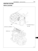
EI–3
EI
PARTS LOCATION
ECM
SECURITY INDICATOR LIGHT:
ID CODE BOX
MAIN BODY ECU
DLC3
STREEING LOCK ECU
CERTIFICATION ECU
ENGINE SWITCH
CLOCK
B128351E01
EI–4
ENGINE IMMOBILISER – ENGINE IMMOBILISER SYSTEM (w/ Smart Key System)
EI
SYSTEM DIAGRAM
Communication table:
Transmitting ECU (Transmitter) Receiving ECU (Receiver) Signals Communication method
Main body ECU Certification ECU Key code recognition signal LIN
ID code box Certification ECU DTC (B2791) signal LIN
ID code box Steering lock ECU
• Steering lock release signal
• Matching request random
number signal
LIN
ID code box Certification ECU
Matching request random number
signal
LIN
Enigine Switch
- Transponder Key
Amplifier (with Key Coil)
Certification ECU
Main Body ECU
ID Code Box
Steering Lock ECU
ECM
LIN Communication Line
B128344E02
ENGINE IMMOBILISER – ENGINE IMMOBILISER SYSTEM (w/ Smart Key System)
EI–5
EI
SYSTEM DESCRIPTION
1. ENGINE IMMOBILISER SYSTEM DESCRIPTION
(a) The immobiliser system is a theft deterrent system
that determines whether to disable starting of the
SFI system based on a comparison of the key's ID
codes and the vehicle's pre-registered code. The
immobiliser system compares the vehicle
certification ECU's pre-registered ID code with the
ID of the key-embedded transponder chip. If the ID
codes do not match, the immobiliser system
activates and the SFI system cannot be started. The
certification ECU manages communication with the
ECM, main body ECU, steering lock ECU and ID
code box. When the ID codes of the transponder
chip and certification ECU match, the certification
ECU authorizes the SFI system to start.
2. FUNCTION OF MAIN COMPONENT
3. SYSTEM FUNCTION
(a) Using entry function
(1) When the driver (or passenger) is sitting in the
vehicle while carrying the key, and the engine
switch is pressed while the brake pedal is
depressed, the main body ECU recognizes that
the engine start operation has occurred and
sends a certification request signal to the
certification ECU. Upon receipt of the
certification request signal, the certification ECU
sends a request signal to the indoor electrical
key oscillator. Upon receipt of the request signal,
the indoor electrical key oscillator sends a
request signal to detect if the key is inside the
vehicle. When the key receives this request
signal, it answers by sending an ID code
containing a response code through the glass
antenna to the door control receiver. Upon
receipt of the ID code, the certification ECU
analyzes the code. If the interior certification
passes, then the main body ECU sends a
certification pass response signal. When the
main body ECU receives this signal, the ACC
relay is switched on and the IG1 and IG2 relays
are switched on in sequence. At this time, the
Component Outline
Transponder key coil/amplifier (built into engine switch)
Receives key ID code, amplifies ID code and outputs the code to the
certification ECU.
Indoor electrical key oscillator
Transmits key detection signals within the detection area in the vehicle
interior upon receiving a transmission request signal from the
certification ECU.
Certification ECU request signal is activated when the key is brought
into the vehicle interior and the engine switch is pushed.
Door control receiver
Receives an ID code from the key in the actuation area and transmits
it to the certification ECU.
Security indicator
Illuminates or starts flashing.
Illumination is controlled by the certification ECU.
EI–6
ENGINE IMMOBILISER – ENGINE IMMOBILISER SYSTEM (w/ Smart Key System)
EI
engine switch indicator illuminates in green.
Then the certification ECU checks that the
power source mode has been changed and
sends a steering lock command signal to the
main body ECU. After receiving this signal, the
main body ECU supplies power to the steering
lock actuator. Then (via the ID code box) the
steering lock ECU confirms that the certification
ECU is certified and drives the steering actuator
motor until the steering lock is unlocked. After
unlocking the steering lock, an unlock completed
signal is sent to the certification ECU. Upon
receipt of this signal, the certification ECU sends
an unset command signal to the ID code box.
Once this signal is received, the ID code box
confirms that the certification ECU is certified,
sends an immobiliser unset command signal to
the ECM and sends a security indicator light off
signal to the certification ECU.
(b) Not using the entry function (when key battery is
depleted)
(1) When the driver is sitting in the vehicle while
carrying the key and the brake pedal is
depressed, the main body ECU recognizes that
the stop light switch is on and sends a key
confirmation request signal to the certification
ECU. Upon receipt of this signal, the certification
ECU drives the immobiliser amplifier built in the
engine switch. At this time, the engine switch
sends an RF wave communication signal to the
immobiliser. If the driver holds the key up to the
engine switch at this time, the engine switch
receives the immobiliser RF wave signal and
responds by sending a radio wave signal. When
the engine switch receives the radio wave signal
from the key, it duplicates the signal and sends
an ID code to the certification ECU. Upon receipt
of the ID code, the code is analyzed. If the
certification passes, a key certification pass
response signal is sent to the main body ECU
while simultaneously sending a sound buzzer
request signal to the meter ECU. When the main
body ECU receives this signal, the ACC relay is
switched on and the IG1 and IG2 relays are
switched on in sequence. At this time, the
engine switch indicator illuminates in green.
Then the certification ECU checks that the
power source mode has been changed and
sends a steering lock command signal to the
main body ECU. After receiving this signal, the
main body ECU supplies power to the steering
lock actuator. Then (via the ID code box) the
steering lock ECU confirms that the certification
ECU is certified and drives the steering actuator
ENGINE IMMOBILISER – ENGINE IMMOBILISER SYSTEM (w/ Smart Key System)
EI–7
EI
motor until the steering lock is unlocked. After
unlocking the steering lock, an unlock completed
signal is sent to the certification ECU. Upon
receipt of this signal, the certification ECU sends
an unset command signal to the ID code box.
Once this signal is received, the ID code box
confirms that the certification ECU is certified,
sends an immobiliser unset command signal to
the ECM and sends a security indicator light off
signal to the certification ECU.
EI–8
ENGINE IMMOBILISER – ENGINE IMMOBILISER SYSTEM (w/ Smart Key System)
EI
HOW TO PROCEED WITH
TROUBLESHOOTING
HINT:
• Use the following procedures to troubleshoot the engine
immobiliser system.
• The intelligent tester should be used in steps 3 and 5.
NEXT
NEXT
(a) Check for DTCs and note any codes that are output (see
page EI-24).
(b) Delete the DTCs.
(c) Recheck for DTCs. Based on the DTCs output above, try
to duplicate the SFI system DTC or engine immobiliser
system DTC by simulating the symptoms indicated by
the DTC.
Result
B
C
A
(a) If the fault is not listed on the problem symptoms table,
proceed to A.
(b) If the fault is listed on the problem symptoms table,
proceed to B.
B
A
1
VEHICLE BROUGHT TO WORKSHOP
2
CRANK ENGINE FOR MORE THAN 10 SECONDS
3
CHECK FOR DTCS
Result Proceed to
DTC output does not reoccur A
SFI system DTC output reoccurs B
Engine immobiliser system DTC output reoccurs C
GO TO SFI SYSTEM
GO TO DTC CHART
4
PROBLEM SYMPTOMS TABLE
GO TO STEP 6
ENGINE IMMOBILISER – ENGINE IMMOBILISER SYSTEM (w/ Smart Key System)
EI–9
EI
(a) DATA LIST/ACTIVE TEST (See page EI-24)
(b) TERMINALS OF ECU (See page EI-15)
NEXT
NEXT
NEXT
5
OVERALL ANALYSIS AND TROUBLESHOOTING
6
ADJUST, REPAIR OR REPLACE
7
CONFIRMATION TEST
END
EI–10
ENGINE IMMOBILISER – ENGINE IMMOBILISER SYSTEM (w/ Smart Key System)
EI
REGISTRATION
1. DESCRIPTION OF CODE REGISTRATION
HINT:
• ID codes are the same as recognition codes for the
wireless transmitter and the engine immobiliser
function. Registering an ID code enables the smart
access system with push-button start, the wireless
door lock control function and the engine immobiliser
function to be operated.
• Code registration is needed when the certification
ECU, ID code box, steering lock ECU or key is
replaced with a new one.
(a) PROCEDURE "1"
The vehicle with the smart access system with
push-button start system does not have a key slot.
Therefore, hold the key close to the engine switch to
register the key, as shown in the illustration below.
Communication distance: 10 mm (0.39 in.) or less from the engine switch.
Engine Switch
Key Key
TOYOTA Mark (Ornament Surface) TOYOTA Mark (Ornament Surface)
Hold the key with its ornament surface within a range of 10 mm (0.39 in.) or less from the engine switch.
B139204E01
ENGINE IMMOBILISER – ENGINE IMMOBILISER SYSTEM (w/ Smart Key System)
EI–11
EI
2. PART REPLACEMENT KEY REGISTRATION
(a) The following table shows ECU replacement and
key registration procedures in case the
malfunctioning ECU has been identified after
troubleshooting the smart access system with push-
button start.
HINT:
• The following procedures indicated in the table
below require the use of the intelligent tester:
New key ID registration
Additional key ID registration
Key ID erasure
ECU code registration
• If all of the registered keys are not available,
replacement of the ID code box is also required.
• A maximum of 7 keys can be registered.
Part to be replaced Condition Procedure Reference
Certification ECU
Customer has brought all keys
1. Replace certification ECU -
2. Reregister all keys (new key ID
registration)
PROCEDURE "B"
Some keys are lost
Key ID codes can be
registered and erased
1. Erase key codes (key ID erasure) PROCEDURE "D"
2. Perform additional key registration
procedure (additional key ID registration)
PROCEDURE "C"
3. Replace certification ECU -
4. Reregister all keys (new key ID
registration)
HINT:
If some keys are not registered during above
steps, they will be disabled because they
cannot be registered later
PROCEDURE "B"
Key ID codes cannot
be either registered or
erased
1. Replace certification ECU -
2. Replace ID code box -
3. Reregister all keys (new key ID
registration)
HINT:
If key codes cannot be erased or additional
keys cannot be registered due to a
malfunction in certification ECU, replace ID
code box and certification ECU. If some keys
are not registered during above steps, they
will be disabled because they cannot be
registered later
PROCEDURE "A"
4. ECU communication ID registration PROCEDURE "F"
ID code box
At least 1 key is available
1. Replace ID code box -
2. Register recognition codes in ECUs (ECU
code registration)
PROCEDURE "E"
3. ECU communication ID registration PROCEDURE "F"
All keys are lost
1. Replace ID code box -
2. Replace certification ECU -
3. Reregister all keys (new key ID
registration)
HINT:
If some keys are not registered during above
steps, they will be disabled because they
cannot be registered later
PROCEDURE "A"
4. ECU communication ID registration PROCEDURE "F"
EI–12
ENGINE IMMOBILISER – ENGINE IMMOBILISER SYSTEM (w/ Smart Key System)
EI
3. KEY REGISTRATION
(a) PROCEDURE "A"
New key ID registration (when replacing certification
ECU and ID code box, or certification ECU, ID code
box and steering lock ECU)
Steering lock ECU
Customer has brought at least 1 key
1. Replace steering lock ECU -
2. Register recognition codes in ECUs (ECU
code registration)
PROCEDURE "E"
All keys are lost
1. Replace steering lock ECU -
2. Replace certification ECU -
3. Replace ID code box -
4. Reregister all keys (new key ID
registration)
HINT:
If some keys are not registered during above
steps, they will be disabled because they
cannot be registered later
PROCEDURE "A"
5. ECU communication ID registration PROCEDURE "F"
Main body ECU No condition required Replace main body ECU -
ECM No condition required
1. Replace ECM -
2. ECU communication ID registration PROCEDURE "F"
Key
Customer has brought at least 1 key
1. Using remaining key, erase lost key code
(key ID erasure)
PROCEDURE "D"
2. Register additional keys as necessary
(additional key ID registration)
PROCEDURE "E"
All keys are lost
1. Replace certification ECU -
2. Replace ID code box -
3. Register all keys (new key ID registration)
HINT:
If customer brings lost keys at later date, they
can be registered using additional key ID
registration function
PROCEDURE "A"
4. ECU communication ID registration PROCEDURE "F"
Part to be replaced Condition Procedure Reference
Process Procedure
1. Start of registration 1. Connect intelligent tester (with CAN VIM) to DLC3
2. Turn engine switch on (IG)
3. Select "SMART ACCESS / ID UTILITY / SMART CODE REG"
from tester menu
HINT:
The engine switch cannot be turned on (IG) more than 10 times. After
connecting tester, turn tester on while turning driver's side door
courtesy light switch on and off repeatedly at 1.5-second intervals or
less to continue key registration procedure
2. Confirmation of ECU code Perform operation according to prompts on tester screen
HINT:
The mode is automatically selected by tester, new registration mode
or add mode
3. Verification of unregistered key *1 Hold unregistered key close to engine switch (For details, refer to
PROCEDURE "1")
Confirm that wireless door lock buzzer sounds. Place unregistered
key on front passenger's side seat
Confirm that wireless door lock buzzer sounds
4. Registration of ID code Perform operation according to prompts on tester screen
5. End of registration Finish new key ID code registration
ENGINE IMMOBILISER – ENGINE IMMOBILISER SYSTEM (w/ Smart Key System)
EI–13
EI
*1: Repeat this process for each key which is to be
registered for the vehicle. Finish the procedure for
each key within 30 seconds. If the procedure for any
of the keys has not been finished within the
specified time, perform registration procedures from
process 1 again. Make sure that only 1 key is in the
cabin during registration procedures. If 2 or more
keys are in the cabin simultaneously, electric waves
will interfere with each other, preventing normal
registration.
(b) PROCEDURE "B"
New key ID registration (when replacing certification
ECU)
*1: Repeat this process for each key registered for
the vehicle. Finish the procedure for each key within
30 seconds. If the procedure for any of the keys has
not been finished within the specified time, perform
registration procedures from process 1 again. If
performing the key confirmation procedure for a key,
the security indicator comes on and remains on until
all the keys are confirmed.
*2: Repeat this process for each key which is to be
registered for the vehicle. Finish the procedure for
each key within 30 seconds. If the procedure for any
of the keys has not been finished within the
specified time, perform registration procedures from
1 again. Make sure that only 1 key is in the cabin
during registration procedures. If 2 or more keys are
in the cabin simultaneously, electric waves will
interfere with each other, preventing normal
registration.
Process Procedure
1. Start of registration 1. Connect intelligent tester (with CAN VIM) to DLC3
2. Turn engine switch on (IG)
3. Select "SMART ACCESS / ID UTILITY / SMART CODE REG"
from tester menu
HINT:
The engine switch cannot be turned on (IG) more than 10 times. After
connecting tester, turn tester on while turning driver's side door
courtesy light switch on and off repeatedly at 1.5-second intervals or
less to continue key registration procedure
2. Confirmation of ECU code Perform operation according to prompts on tester screen
HINT:
The mode is automatically selected by tester, new registration mode
or add mode
3. Confirmation of all registered keys *1 Hold unregistered key close to engine switch (For details, refer to
PROCEDURE "1")
Confirm that wireless door lock buzzer sounds
4. Confirmation of ECU code Perform operation according to prompts on tester screen
5. Verification of unregistered key *2 Hold unregistered key close to engine switch (For details, refer to
PROCEDURE "1")
Confirm that wireless door lock buzzer sounds. Place unregistered
key on front passenger side seat
Confirm that wireless door lock buzzer sounds
5. Registration of ID code Perform operation according to prompts on tester screen
6. End of registration Finish new key ID code registration
EI–14
ENGINE IMMOBILISER – ENGINE IMMOBILISER SYSTEM (w/ Smart Key System)
EI
(c) PROCEDURE "C"
Additional key ID registration
*1: Perform this process for one of the keys
registered for the vehicle. Finish the procedure
within 30 seconds. If the procedure has not been
finished within the specified time, perform
registration procedures from process 1 again.
*2: Repeat this process for each key which is to be
registered for the vehicle. Finish the procedure for
each key within 30 seconds. If the procedure for any
of the keys has not been finished within the
specified time, perform registration procedures from
1 again. Make sure that only 1 key is in the cabin
during registration procedures. If 2 or more keys are
in the cabin simultaneously, electric waves will
interfere with each other, preventing normal
registration.
(d) PROCEDURE "D"
Key ID erasure
HINT:
Erase all registered key codes except one.
Process Procedure
1. Start of registration 1. Connect intelligent tester (with CAN VIM) to DLC3
2. Turn engine switch on (IG)
3. Select "SMART ACCESS / ID UTILITY / SMART CODE REG"
from tester menu
2. Confirmation of registered key *1 Perform operation according to prompts on intelligent tester screen
HINT:
The mode is automatically selected by tester, new registration mode
or add mode
Hold unregistered key close to engine switch (For details, refer to
PROCEDURE "1")
Confirm that wireless door lock buzzer sounds once
3. Confirmation of ECU code Perform operation according to prompts on tester screen
4. Verification of unregistered key *2 Hold unregistered key close to engine switch (For details, refer to
PROCEDURE "1")
Confirm that wireless door lock buzzer sounds. Place unregistered
key on front passenger's side seat
Confirm that wireless door lock buzzer sounds
5. Registration of ID code Perform operation according to prompts on tester screen
6. End of registration Finish key ID code registration
Process Procedure
1. Start of erasure 1. Connect intelligent tester (with CAN VIM) to DLC3
2. Turn engine switch on (IG)
3. Select "SMART ACCESS / ID UTILITY / SMART CODE ERS"
from tester menu
2. Confirmation of registered key *1 Perform operation according to prompts on intelligent tester screen
Hold unregistered key close to engine switch (For details, refer to
PROCEDURE "1")
Confirm that wireless door lock buzzer sounds once
3. Confirmation of ECU code Perform operation according to prompts on tester screen
4. Erasure of ID code Perform operation according to prompts on tester screen
5. End of erasure Finish key ID code erasure
ENGINE IMMOBILISER – ENGINE IMMOBILISER SYSTEM (w/ Smart Key System)
EI–15
EI
*1: Perform this process for one of the keys
registered for the vehicle. Finish the procedure
within 30 seconds. If the procedure has not been
finished within the specified time, perform erasure
procedures from process 1 again.
(e) PROCEDURE "E"
ECU code registration
*1: Perform this process for one of the keys
registered for the vehicle. Finish the procedure
within 30 seconds. If the procedure has not been
finished within the specified time, perform erasure
procedures from process 1 again.
(f) PROCEDURE "F"
ECU communication ID registration
NOTICE:
• The ECU communication ID should be
registered when the ID code box and/or the
ECM is replaced in order to match these ECM
communication ID.
• The engine cannot be started unless the ECM
communication ID matches.
Register the ECU communication ID.
(1) Using SST, connect terminals TC and CG of
the DLC3.
SST 09843-18040
Process Procedure
1. Start of registration 1. Connect intelligent tester (with CAN VIM) to DLC3
2. Turn engine switch on (IG)
3. Select "SMART ACCESS / ID UTILITY / ECU COMM ID REG / ID
Code Box and Steering Lock" from tester menu
2. Confirmation of registered key *1 Hold unregistered key close to engine switch (For details, refer to
PROCEDURE "1")
Confirm that wireless door lock buzzer sounds once
3. Registration of ECU code Perform operation according to prompts on tester screen
4. End of registration Finish ECU code registration
SST
CG
TC
B139171E01
EI–16
ENGINE IMMOBILISER – ENGINE IMMOBILISER SYSTEM (w/ Smart Key System)
EI
(2) Turn the engine switch on (IG) and leave it for
30 minutes.
HINT:
Do not start the engine.
(3) Turn the engine switch off and disconnect
terminals TC and CG.
(4) Check that the engine starts.
ENGINE IMMOBILISER – ENGINE IMMOBILISER SYSTEM (w/ Smart Key System)
EI–17
EI
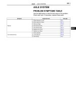
PROBLEM SYMPTOMS TABLE
HINT:
Use the table below to help determine the cause of the
problem symptom. The potential cases of the symptoms are
listed in order of probability in the "Suspected Area" column
of the table. Check each symptom by checking the suspected
area in the order they are listed. Replace parts as necessary.
Engine Immobiliser System:
Symptom Suspected area See page
Engine does not start
1. Key EI-24
2. ID code box power source circuit EI-45
3. Certification ECU power source circuit EI-48
4. Steering lock ECU power source circuit SR-30
5. Smart access system DL-142
6. SFI system ES-15
EI–18
ENGINE IMMOBILISER – ENGINE IMMOBILISER SYSTEM (w/ Smart Key System)
EI
TERMINALS OF ECU
1. CHECK ENGINE SWITCH
(a) Disconnect the E52 switch connector.
(b) Measure the resistance according to the value(s) in
the table below.
If the result is not as specified, there may be a
malfunction on the wire harness side.
(c) Reconnect the E52 switch connector.
(d) Measure the resistance and voltage according to
the value(s) in the table below.
HINT:
*: Remove the key battery before performing this
inspection.
If the result is not as specified, the switch may have
a malfunction.
E52
B146454E01
Symbols (Terminal No.) Wiring Color Terminal Description Condition Specified Condition
AGND (E52-8) - Body ground G - Body ground Ground Always Below 1 Ω
Symbols (Terminal No.) Wiring Color Terminal Description Condition Specified Condition
AGND (E52-8) - Body ground G - Body ground Ground Always Below 1 Ω
VC5 (E52-14) - AGND (E52-8) R - G Power supply
Key is not in cabin Below 1 V
Press engine switch 4.6 to 5.4 V
CODE (E52-10) - AGND (E52-8) W - G
Demodulated signal of key
code data
Key is not in cabin Below 1 V
Press engine switch and
hold key close to engine
switch*
Pulse generation
(see waveform 1)
TXCT (E52-9) - AGND (E52-8) GR - G Key code output signal
Key is not in cabin Below 1 V
Press engine switch and
hold key close to engine
switch*
Pulse generation
(see waveform 2)
ENGINE IMMOBILISER – ENGINE IMMOBILISER SYSTEM (w/ Smart Key System)
EI–19
EI
(e) Inspect using an oscilloscope.
(1) Waveform 1 (Reference)
HINT:
*: Remove the key battery before performing this
inspection.
(2) Waveform 2 (Reference)
HINT:
*: Remove the key battery before performing this
inspection.
2. CHECK CERTIFICATION ECU
(a) Disconnect the E58 ECU connector.
(b) Measure the resistance and voltage according to
the value(s) in the table below.
If the result is not as specified, there may be a
malfunction on the wire harness side.
(c) Reconnect the E58 ECU connector.
GND
Tool Setting: 2 V/DIV., 20 ms./DIV.
B139211E01
Item Content
Symbols (Terminal No.) CODE (E52-10) - AGND (E52-8)
Tool Setting 2 V/DIV., 20 ms./DIV.
Condition
Press engine switch and hold key close
to engine switch*
GND
Tool Setting: 2 V/DIV., 20 ms./DIV.
B139212E01
Item Content
Symbols (Terminal No.) TXCT (E52-9) - AGND (E52-8)
Tool Setting 2 V/DIV., 20 ms./DIV.
Condition
Press engine switch and hold key close
to engine switch*
1
12
2
13
3
14
4
15
5
16
6
123456
17181920212223
7
24
8
25
9
789
26
10
27
11
28
19
18
2021222324252627282930313233
10
34
11
35
12
36
13
37
15
14
38
16
39
17
40
E58
B106648E23
Symbols (Terminal No.) Wiring Color Terminal Description Condition Specified Condition
E (E58-17) - Body ground W-B - Body ground Ground Always Below 1 Ω
+B (E58-1) - E (E58-17) W - W-B +B power supply Always 10 to 14 V
IG (E58-18) - E (E58-17) LG - W-B Ignition power supply Engine switch off Below 1 V
EI–20
ENGINE IMMOBILISER – ENGINE IMMOBILISER SYSTEM (w/ Smart Key System)
EI
(d) Measure the resistance and voltage according to
the value(s) in the table below.
HINT:
*: Remove the key battery before performing this
inspection.
If the result is not as specified, the ECU may have a
malfunction.
(e) Inspect using an oscilloscope.
(1) Waveform 1 (Reference)
HINT:
*: Remove the key battery before performing this
inspection.
(2) Waveform 2 (Reference)
HINT:
*: Remove the key battery before performing this
inspection.
Symbols (Terminal No.) Wiring Color Terminal Description Condition Specified Condition
AGND (E58-40) - Body ground G - Body ground Engine switch ground Always Below 1 Ω
VC5 (E58-30) - AGND (E58-40) R - G
Engine switch power
supply
Key is not in cabin Below 1 V
Press engine switch* 4.6 to 5.4 V
CODE (E58-9) - AGND (E58-40) W - G Engine switch CODE input
Key is not in cabin Below 1 V
Press engine switch and
hold key close to engine
switch*
Pulse generation (see
waveform 1)
TXCT (E58-8) - AGND (E58-40) GR - G
Engine switch TXCT
output
Key is not in cabin Below 1 V
Press engine switch and
hold key close to engine
switch*
Pulse generation (see
waveform 2)
GND
Tool Setting: 2 V/DIV., 20 ms./DIV.
B139211E01
Item Content
Symbols (Terminal No.) CODE (E58-9) - AGND (E58-40)
Tool Setting 2 V/DIV., 20 ms./DIV.
Condition
Press engine switch and hold key close
to engine switch*
GND
Tool Setting: 2 V/DIV., 20 ms./DIV.
B139212E01
Item Content
Symbols (Terminal No.) TXCT (E58-8) - AGND (E58-40)
Tool Setting 2 V/DIV., 20 ms./DIV.
Condition
Press engine switch and hold key close
to engine switch*
ENGINE IMMOBILISER – ENGINE IMMOBILISER SYSTEM (w/ Smart Key System)
EI–21
EI
3. CHECK ID CODE BOX
(a) Disconnect the E50 ECU connector.
(b) Measure the resistance and voltage according to
the value(s) in the table below.
If the result is not as specified, there may be a
malfunction on the wire harness side.
(c) Reconnect the E50 ECU connector.
(d) Measure the voltage according to the value(s) in the
table below.
If the result is not as specified, the ECU may have a
malfunction.
(e) Inspect using an oscilloscope.
(1) Waveform 1 (Reference)
E50
B118534E03
Symbols (Terminal No.) Wiring Color Terminal Description Condition Specified Condition
GND (E50-8) - Body ground W-B - Body ground Ground Always Below 1 Ω
+B (E50-1) - GND (E50-8) W - W-B +B power supply Always 10 to 14 V
Symbols (Terminal No.) Wiring Color Terminal Description Condition Specified Condition
EFII (E50-5) - GND (E50-8) G - W-B ECM input signal
Engine switch off Below 1 V
Engine switch on (IG)
Pulse generation
(see waveform 1)
EFIO (E50-6) - GND (E50-8) L - W-B ECM output signal
Engine switch off Below 1 V
Engine switch on (IG)
Pulse generation
(see waveform 2)
GND
Tool Setting: 10 V/DIV., 100 ms./DIV.
B139209E01
Item Content
Symbols (Terminal No.) EFII (E50-5) - GND (E50-8)
Tool Setting 10 V/DIV., 100 ms./DIV.
Condition Engine switch on (IG)
EI–22
ENGINE IMMOBILISER – ENGINE IMMOBILISER SYSTEM (w/ Smart Key System)
EI
(2) Waveform 2 (Reference)
4. CHECK STEERING CONTROL ECU
(a) Disconnect the E51 ECU connector.
(b) Measure the resistance and voltage according to
the value(s) in the table below.
If the result is not as specified, there may be a
malfunction on the wire harness side.
GND
Tool Setting: 10 V/DIV., 100 ms./DIV.
B139210E01
Item Content
Symbols (Terminal No.) EFIO (E50-6) - GND (E50-8)
Tool Setting 10 V/DIV., 100 ms./DIV.
Condition Engine switch on (IG)
E51
B118684E03
Symbols (Terminal No.) Wiring Color Terminal Description Condition Specified Condition
SGND (E51-2) - Body ground W-B - Body ground Ground Always Below 1 Ω
GND (E51-1) - Body ground W-B - Body ground Ground Always Below 1 Ω
B (E51-7) - Body ground P - Body ground +B power supply Always 10 to 14 V
IG2 (E51-6) - Body ground B - Body ground Ignition power supply
Engine switch off 0 V
Engine switch on (IG) 10 to 14 V
ENGINE IMMOBILISER – ENGINE IMMOBILISER SYSTEM (w/ Smart Key System)
EI–23
EI
5. CHECK ECM
(a) Measure the resistance and voltage according to
the value(s) in the table below.
If the result is not as specified, the ECM may have a
malfunction.
C55
A55
A107881E14
Symbols (Terminal No.) Wiring Color Terminal Description Condition Specified Condition
E1 (C55-81) - Body ground W-B - Body ground Ground Always Below 1 Ω
E01 (C55-22) - Body ground W-B - Body ground Ground Always Below 1 Ω
E02 (C55-21) - Body ground B-W - Body ground Ground Always Below 1 Ω
E03 (C55-104) - Body ground B - Body ground Ground Always Below 1 Ω
E04 (C55-23) - Body ground W - Body ground Ground Always Below 1 Ω
E05 (C55-46) - Body ground W - Body ground Ground Always Below 1 Ω
ME01 (C55-20) - Body ground B - Body ground Ground Always Below 1 Ω
BATT (A55-20) - E1 (C55-81) Y - W-B
Battery (for measuring
battery voltage and for
ECM memory)
Always 10 to 14 V
+B (A55-2) - E1 (C55-81) R - W-B Power source of ECM
Engine switch off Below 1 V
Engine switch on (IG) 10 to 14 V
IMI (A55-11) - E1 (C55-81) Y - W-B
Immobiliser code ECU
input signal
Engine switch off Below 1 V
Engine switch on (IG)
Pulse generation
(see waveform 1)
IMO (A55-10) - E1 (C55-81) G - W-B
Immobiliser code ECU
output signal
Engine switch off Below 1 V
Engine switch on (IG)
Pulse generation
(see waveform 2)
EI–24
ENGINE IMMOBILISER – ENGINE IMMOBILISER SYSTEM (w/ Smart Key System)
EI
(b) Inspect using an oscilloscope.
(1) Waveform 1 (Reference)
(2) Waveform 2 (Reference)
6. CHECK MAIN BODY ECU (INSTRUMENT PANEL J/B)
(a) Disconnect the IF and IM junction block connectors.
GND
Tool Setting: 10 V/DIV., 100 ms./DIV.
B139210E01
Item Content
Symbols (Terminal No.) IMI (A55-11) - E1 (C55-81)
Tool Setting 10 V/DIV., 100 ms./DIV.
Condition Engine switch on (IG)
GND
Tool Setting: 10 V/DIV., 100 ms./DIV.
B139209E01
Item Content
Symbols (Terminal No.) IMO (A55-10) - E1 (C55-10)
Tool Setting 10 V/DIV., 100 ms./DIV.
Condition Engine switch on (IG)
ENGINE IMMOBILISER – ENGINE IMMOBILISER SYSTEM (w/ Smart Key System)
EI–25
EI
(b) Disconnect the E8, E7 and E6 main body ECU
connectors.
(c) Measure the resistance and voltage according to
the value(s) in the table below.
Vehicle Rear Side
Vehicle Front Side
IM
IF
E7
E6
E8
B128347E01
Symbols (Terminal No.) Wiring Color Terminal Description Condition Specified Condition
GND1 (IF-10) - Body ground W-B - Body ground Ground Always Below 1 Ω
GND2 (IM-9) - Body ground W-B - Body ground Ground Always Below 1 Ω
GND3 (E8-1) - Body ground W-B - Body ground Ground Always Below 1 Ω
AM1 (E7-6) - Body ground L - Body ground +B power supply Always 10 to 14 V
AM2 (E6-1) - Body ground L - Body ground +B power supply Always 10 to 14 V