ABB ACS550 Drive Manuals
Bạn đang xem bản rút gọn của tài liệu. Xem và tải ngay bản đầy đủ của tài liệu tại đây (6.8 MB, 262 trang )
Drive
IT
Low Voltage AC Drives
User’s Manual
ACS550-01 Drives (0.75
…110 kW)
ACS550-U1 Drives (1
…150 HP)
2 ACS550 User’s Manual
ACS550 Drive Manuals
The Industrial
IT
wordmark and Product names in the form
Drive
IT
are registered or pending trademarks of ABB.
CANopen is a registered trademark of CAN in Automation
e.V.
ControlNet is a registered trademark of ControlNet
International.
DeviceNet is a registered trademark of Open DeviceNet
Vendor Association.
DRIVECOM is a registered trademark of DRIVECOM User
Organization.
Interbus is a registered trademark of Interbus Club.
LonWorks is a registered trademark of Echelon Corp.
Metasys is a registered trademark of Johnson Controls Inc.
Modbus and Modbus Plus are registered trademarks of
Schneider Automation Inc.
Profibus is a registered trademark of Profibus Trade Org.
Profibus-DP is a registered trademark of Siemens AG.
GENERAL MANUALS
ACS550-01/U1 User's Manual (0.75…110 kW) /
(1…150 HP)
• Safety
•Installation
• Start-Up
• Embedded Fieldbus
• Fieldbus Adapter
• Diagnostics
• Maintenance
• Technical Data
ACS550-02/U2 User's Manual (110…355 kW) /
(150…550 HP)
• Safety
•Installation
• Start-Up
• Diagnostics
• Maintenance
• Technical Data
ACS550 Technical Reference Manual
(available in electronic format only)
• Detailed Product Description
– Technical product description including Dimensional
drawings
– Cabinet mounting information including power
losses
– Software and control including complete parameter
descriptions
– User interfaces and control connections
– Complete options descriptions
– Spare parts
–Etc.
• Practical Engineering Guides
– PID & PFC engineering guides
– Dimensioning and sizing guidelines
– Diagnostics and Maintenance information
–Etc.
OPTION MANUALS
(Fieldbus Adapters, I/O Extension Modules etc., manuals
delivered with optional equipment)
Relay Output Extension Module (typical title)
•Installation
• Start-Up
• Diagnostics
• Technical Data
© 2004 ABB Inc. All Rights Reserved.
Update Notice
1
Update Notice
NEW LANGUAGE VERSIONS FOR ASSISTANT CONTROL PANEL
Assistant Control Panel is available in three language versions: ACS-CP-A,
ACS-CP-L and ACS-CP-D.
The notice concerns ACS550-01/U1 User’s Manual Code: 3AFE68800269 Rev A
Valid: from 25.9.2006 until the release of Rev E of the manual
Contents: the main new features and changes which are not
yet updated to the manual. The sections have a label NEW
(=
new feature), or CHANGE
(= changed feature), or DELETED
(= deleted feature).
A summary of the updates is given below.
NEW: Assistant Control Panel language versions
Parameters and parameter values
380 480 V types
DELETED: Underload parameters
9901 LANGUAGE
Selects the display language. There are three different Assistant Control Panels, each supporting a different
language set.
Code Revision Language
3AFE64804588
(3AUA0000001418)
D
English EN
3AFE64783611 D
Danish DA
3AFE64783653 D
German DE
3AFE64783661 D
Spanish ES
3AFE64783670 D
Finnish FI
3AFE64783688 D
French FR
3AFE64783696 D
Italian IT
3AFE64783700 D
Dutch NL
3AFE64783718 D
Portuguese PT
3AFE64783726 D
Russian RU
3AFE64783734 D
Swedish SV
Assistant Control Panel ACS-CP-A (Area 1):
Assistant Control Panel ACS-CP-L (Area 2):
Assistant Control Panel ACS-CP-D (Asia):
0 = ENGLISH 1 = ENGLISH (AM)2 = DEUTSCH 3 = ITALIANO 4 = ESPAÑOL
5 = PORTUGUES 6 = NEDERLANDS 7 = FRANÇAIS 8 = DANSK 9 = SUOMI
10 = SVENSKA 15 = MAGYAR
0 = ENGLISH 2 = DEUTSCH 11 = RUSSKI 12 = POLSKI 13 = TÜRKÇE
14 = CZECH
0 = ENGLISH 1 = CHINESE 2 = KOREAN
Update Notice
2
NEW PARAMETERS AND PARAMETER VALUES
This new group defines supervision of user adjustable load curves (motor torque as
a function of frequency). The curve is defined by five points. - The function replaces
deleted underload parameters 3013…3015.
Code Description
3701 USER LOAD C MODE
Supervision mode for the user adjustable load
curves. This functionality replaces the former
underload supervision in Group 30: FAULT
FUNCTIONS.
0 =
NOT SEL – Supervision is not active.
1 = UNDERLOAD – Supervision for the torque
dropping below the underload curve.
2 =
OVERLOAD – Supervision for the torque
exceeding the overload curve.
3 =
BOTH – Supervision for the torque dropping
below the underload curve or exceeding the
overload curve.
3702 USER LOAD C FUNC
Action wanted during load supervision.
1 =
FAULT – A fault is generated when the condition defined by 3701 USER LOAD C MODE has been valid longer than
the time set by 3703
USER LOAD C TIME.
2 = ALARM – An alarm is generated when the condition defined by 3701 USER LOAD C MODE has been valid longer than
half of the time defined by 3703
USER LOAD C TIME.
3703 USER LOAD C TIME
Defines the time limit for generating a fault. Half of this time is used as the limit for generating an alarm.
3704 LOAD FREQ 1
Defines the frequency value of the first curve definition point. Must be smaller than 3707
LOAD FREQ 2.
3705 LOAD TORQ LOW 1
Defines the torque value of the first underload curve definition point. Must be smaller than 3706
LOAD TORQ HIGH 1.
3706 LOAD TORQ HIGH 1
Defines the torque value of the first overload curve definition point.
3707 LOAD FREQ 2
Defines the frequency value of the second curve definition point. Must be smaller than 3710
LOAD FREQ 3.
3708 LOAD TORQ LOW 2
Defines the torque value of the second underload curve definition point. Must be smaller than 3709
LOAD
TORQ
HIGH
2.
3709 LOAD TORQ HIGH 2
Defines the torque value of the second overload curve definition point.
3710 LOAD FREQ 3
Defines the frequency value of the third load curve definition point.
3711 LOAD TORQ LOW 3
Defines the torque value of the third underload curve definition point.
Must be smaller than 3712
LOAD
TORQ
HIGH
3.
3712 LOAD TORQ HIGH 3
Defines the torque value of the third overload curve definition point.
3713 LOAD FREQ 4
Defines the frequency value of the fourth load curve definition point.
3714 LOAD TORQ LOW 4
Defines the torque value of the fourth underload curve definition point.
Must be smaller than 3715
LOAD
TORQ
HIGH
4.
Overload area
Underload area
Allowed operating area
P3706
P3705
P3704
P3709
P3708
P3707
P3712
P3711
P3710
P3715
P3714
P3713
P3718
P3717
P3716
Motor torque (%)
Output frequency (Hz)
Update Notice
3
FlashDrop
Drive control board (CB) temperature.
PFC control
3715 LOAD TORQ HIGH 4
Defines the torque overvalue of the fourth load curve definition point.
3716 LOAD FREQ 5
Defines the frequency value of fifth load curve definition point.
3717 LOAD TORQ LOW 5
Defines the torque value of the fifth underload curve definition point.
Must be smaller than 3718
LOAD
TORQ
HIGH
5.
3718 LOAD TORQ HIGH 5
Defines the torque value of the fifth overload curve definition point.
1611 PARAMETER VIEW
Selects the parameter view, i.e. which parameters are shown.
Note: This parameter is visible only when it is activated by the optional FlashDrop device. FlashDrop allows fast
customization of the parameter list, e.g. selected parameters can be hidden. For more information, see MFDT-01
FlashDrop User’s Manual [3AFE68591074 (English)].
FlashDrop parameter values are activated by setting parameter 9902 to 31 (
LOAD FD SET).
0 = DEFAULT – Complete long and short parameter lists are shown.
1 =
FLASHDROP – FlashDrop parameter list is shown. Does not include short parameter list. Parameters that are
hidden by the FlashDrop device are not visible.
9902 APPLIC MACRO
31 =
LOAD FD SET – FlashDrop parameter values as defined by the FlashDrop file. Parameter view is selected by
parameter 1611 PARAMETER VIEW.
0150 CB TEMP
Temperature of the drive control board in degrees Celsius/Fahrenheit.
Note: Some drives have a control board (OMIO) that does not support this feature. These drives always show the
constant value of 25.0 ºC.
3024 CB TEMP FAULT
Defines the drive response to control board overheating.
0 =
DISABLE – No response
1 = ENABLE – Displays fault 37 (CB OVERTEMP) and the drive coasts to stop.
8118 AUTOCHNG INTERV
-0.1 =
TEST MODE – Forces the interval to value 36…48 s.
8128 AUX START ORDER
Sets the start order of the auxiliary motors.
1 =
EVEN RUNTIME – Time sharing is active. The start order depends on the run times.
2 = RELAY ORDER – The start order is fixed to be the order of the relays.
Code Description
Update Notice
4
Start/Stop
Encoder
This group defines the encoder settings. For more information, see User’s Manual
for Pulse Encoder Interface Module OTAC-01 [3AUA0000001938 (English)].
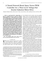
2112 ZERO SPEED DELAY
Defines the delay for the Zero Speed Delay function. If parameter value is set to zero, Zero Speed Delay function is
disabled.
The function is useful in applications where a smooth and quick restarting is essential. During the delay the drive
knows accurately the rotor position.
Zero speed delay can be used e.g. with jogging function or mechanical brake.
No Zero Speed Delay
The drive receives a stop command and decelerates along a ramp. When the motor actual speed falls below an
internal limit (called Zero Speed), the speed controller is switched off. The drive modulation is stopped and the motor
coasts to standstill.
With Zero Speed Delay
The drive receives a stop command and decelerates along a ramp. When the actual motor speed falls below an
internal limit (called Zero Speed), the zero speed delay function activates. During the delay the functions keeps the
speed controller live: The drive modulates, motor is magnetized and drive is ready for a quick restart.
2113 START DELAY
Defines the Start delay. After the conditions for start have been fulfilled, the drive waits until the delay has elapsed
and then starts the motor. Start delay can be used with all start modes.
• If
START DELAY = zero, the delay is disabled.
Code Description
5001 PULSE NR
Number of encoder pulses per one revolution (ppr).
5002 ENCODER ENABLE
Enables/disables the encoder.
0 = DISABLE
1 = ENABLE.
5003 ENCODER FAULT
Defines the operation of the drive if a failure is detected in communication between the pulse encoder and the pulse
encoder interface module, or between the module and the drive.
1 =
FAULT – The drive trips on fault ENCODER ERR.
2 = ALARM – The drive generates alarm ENCODER ERR.
5010 Z PLS ENABLE
Enables/disables the encoder zero (Z) pulse. Zero pulse is used for position reset.
0 = DISABLE
1 = ENABLE.
5011 POSITION RESET
Enables/disables the position reset.
0 = DISABLE
1 = ENABLE.
Speed
t
Zero Speed
Speed
t
Zero Speed
Delay
No Zero Speed Delay With Zero Speed Delay
Speed controller
switched off: Motor
coasts to stop.
Speed controller remains live.
Motor is decelerated to true 0
speed.
Update Notice
5
Encoder related actual signals:
Miscellaneous
0146 MECH ANGLE
Calculated mechanical angle.
0147 MECH REVS
Mechanical revolutions, i.e. the motor shaft revolutions, calculated by the encoder.
0148 Z PLS DETECTED
Encoder zero pulse detector.
0 =
NOT DETECTED
1 = DETECTED.
0158 PID COMM VALUE 1
Data received from fieldbus for PID control (PID1 and PID2).
0159 PID COMM VALUE 2
Data received from fieldbus for PID control (PID1 and PID2).
1004 JOGGING SEL
Defines the signal that activates the jogging function. Jogging uses Constant Speed 7 for speed reference and ramp
pair 2 for accelerating and decelerating. When the jogging activation signal is lost, the drive uses ramp stop to
decelerate to zero speed, even if coast stop is used in normal operation (parameter 2102). The jogging status can be
parameterized to relay outputs (parameter 1401). The jogging status is also seen in DCU Profile status bit 21.
0 =
NOT SEL – Disables the jogging function.
1 =
DI1 – Activates/de-activates jogging based on the state of DI1 (DI1 activated = jogging active; DI1 de-activated =
jogging inactive).
2…6 =
DI2…DI6 – Activates jogging based on the state of the selected digital input. See DI1 above.
-1 =
DI1(INV) – Activates jogging based on the state of DI1 (DI1 activated = jogging inactive; DI1 de-activated = jogging
active).
-2…-6 =
DI2(INV)…DI6(INV) – Activates jogging based on the state of the selected digital input. See DI1(INV) above.
1103 REF1 SELECT
20 =
KEYPAD(RNC) – Defines the control panel as the reference source. A Stop command resets the reference to zero
(R stands for reset.). Changing the control source (EXT1 to EXT2, EXT2 to EXT1) does not copy the reference.
21 =
KEYPAD(NC) – Defines the control panel as the reference source. A Stop command does not reset the reference
to zero. The reference is stored. Changing the control source (
EXT1 to EXT2, EXT2 to EXT1) does not copy the
reference.
1401 RELAY OUTPUT 1
46 =
START DELAY – Energize relay when a start delay is active.
52 = JOG ACTIVE – Energize relay when the jogging function is active.
2101 START FUNCTION
8 =
RAMP – Immediate start from zero frequency.
2619 DC STABILIZER
Enables or disables the DC voltage stabilizer. The DC stabilizer is used in scalar control mode to prevent possible
voltage oscillations in the drive DC bus caused by motor load or weak supply network. In case of voltage variation the
drive tunes the frequency reference to stabilize the DC bus voltage and therefore the load torque oscillation.
0 = DISABLE – Disables DC stabilizer.
1 =
ENABLE – Enables DC stabilizer.
Update Notice
6
DELETED PARAMETERS
New group 37 USER LOAD CURVE replaces deleted underload parameters.
4010 SET POINT SEL
20 = PID2OUT – Defines PID controller 2 output (parameter 0127 PID 2 OUTPUT) as the reference source.
4014 FBK SEL
11 =
COMM FBK 1 – Signal 0158 PID COMM VALUE 1 provides the feedback signal.
12 = COMM FBK 2 – Signal 0159 PID COMM VALUE 2 provides the feedback signal.
13 =
AVE(ACT1,2) – The average of ACT1 and ACT2 provides the feedback signal.
4016 ACT1 INPUT
6 =
COMM ACT 1 – Uses value of signal 0158 PID COMM VALUE 1 for ACT1.
7 =
COMM ACT 2 – Uses value of signal 0159 PID COMM VALUE 2 for ACT1.
4017 ACT2 INPUT
6 =
COMM ACT 1 – Uses value of signal 0158 PID COMM VALUE 1 for ACT2.
7 =
COMM ACT 2 – Uses value of signal 0159 PID COMM VALUE 2 for ACT2.
4027 PID 1 PARAM SET
12 = 2-ZONE MIN – The drive calculates the difference between setpoint 1 and feedback 1 as well as setpoint 2 and
feedback 2. The drive will control the zone (and select the set) which has a larger difference.
• A positive difference (a setpoint higher than the feedback) is always larger than a negative difference. This keeps
feedback values at or above the setpoint.
• Controller does not react to the situation of feedback above setpoint if another zone's feedback is closer to its
setpoint.
13 = 2-
ZONE MAX – The drive calculates the difference between setpoint 1 and feedback 1 as well as setpoint 2 and
feedback 2. The drive will control the zone (and select the set) which has a smaller difference.
• A negative difference (a setpoint lower than the feedback) is always smaller than a positive difference. This keeps
feedback values at or below the setpoint.
• Controller does not react to the situation of feedback below setpoint if another zone's feedback is closer to its
setpoint.
14 = 2-
ZONE AVE – The drive calculates the difference between setpoint 1 and feedback 1 as well as setpoint 2 and
feedback 2. In addition, it calculates the average of the deviations, and uses it to control zone 1. Therefore one
feedback is kept above its setpoint and another is kept as much below its setpoint.
5127 FBA PAR REFRESH
Validates any changed fieldbus parameter settings.
0 =
DONE – Refreshing done.
1 =
REFRESH – Refreshing.
• After refreshing, the value reverts automatically to
DONE.
3013 UNDERLOAD FUNCTION
3014 UNDERLOAD TIME
3015 UNDERLOAD CURVE
Update Notice
7
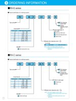
NEW 380 480 V TYPES
1
Not available in ACS550-U1 series
2
Not available in ACS550-01 series
Type code Normal use Heavy-duty use
Frame
size
ACS550-x1-
see below
I
2N
A
P
N
kW
P
N
hp
I
2hd
A
P
hd
kW
P
hd
hp
Three-phase supply voltage, 380…480 V
-045A-4 45 22.0 30 38 18.5 25 R3
-087A-4
1
87 45.0 60 77 37.0 60 R4
-097A-4
2
96 45.0 75 77 37 60 R4
-125A-4 125 55.0
100 96 45.0 75 R5
Update Notice
8
ACS550 User’s Manual 3
Safety
Safety
Warning! The ACS550 adjustable speed AC drive should ONLY be installed by
a qualified electrician.
Warning! Even when the motor is stopped, dangerous voltage is present at the
Power Circuit terminals U1, V1, W1 and U2, V2, W2 and, depending on the
frame size, UDC+ and UDC-, or BRK+ and BRK
Warning! Dangerous voltage is present when input power is connected. After
disconnecting the supply, wait at least 5 minutes (to let the intermediate circuit
capacitors discharge) before removing the cover.
Warning! Even when power is removed from the input terminals of the
ACS550, there may be dangerous voltage (from external sources) on the
terminals of the relay outputs R01
…R03.
Warning! When the control terminals of two or more drive units are connected
in parallel, the auxiliary voltage for these control connections must be taken
from a single source which can either be one of the units or an external
supply.
Warning! The ACS550-01/U1 is not a field repairable unit. Never attempt to
repair a malfunctioning unit; contact the factory or your local Authorized
Service Center for replacement.
Warning! The ACS550 will start up automatically after an input voltage
interruption if the external run command is on.
Warning! The heat sink may reach a high temperature. See "Technical Data" on
page 215.
Warning! If the drive will be used in a floating network, remove screws at EM1
and EM3 (Frame size R1
…R4), or F1 and F2 (Frame size R5 or R6). See
diagrams on page 15 and page 16 respectively. Also see "Unsymmetrically
Grounded Networks" and "Floating Networks" on page 221.
Warning! Do not attempt to install or remove EM1, EM3, F1 or F2 screws while
power is applied to the drive’s input terminals.
Note! For more technical information, contact the factory or your local ABB sales
representative.
4 ACS550 User’s Manual
Safety
Use of Warnings and Notes
There are two types of safety instructions throughout this manual:
• Notes draw attention to a particular condition or fact, or give information on a
subject.
• Warnings caution you about conditions which can result in serious injury or death
and/or damage to the equipment. They also tell you how to avoid the danger. The
warning symbols are used as follows:
Dangerous voltage warning warns of high voltage which can cause physical injury
and/or damage to the equipment.
General warning warns about conditions, other than those caused by electricity,
which can result in physical injury and/or damage to the equipment
ACS550 User’s Manual 5
Table of Contents
Table of Contents
Safety
Use of Warnings and Notes . . . . . . . . . . . . . . . . . . . . . . . . . . . . . . . . . . . . . . . . 4
Table of Contents
Installation
Installation Flow Chart . . . . . . . . . . . . . . . . . . . . . . . . . . . . . . . . . . . . . . . . . . . . 7
Preparing for Installation . . . . . . . . . . . . . . . . . . . . . . . . . . . . . . . . . . . . . . . . . . 8
Installing the Drive . . . . . . . . . . . . . . . . . . . . . . . . . . . . . . . . . . . . . . . . . . . . . . 11
Start-Up
Control Panels . . . . . . . . . . . . . . . . . . . . . . . . . . . . . . . . . . . . . . . . . . . . . . . . . 27
Assistant Control Panel . . . . . . . . . . . . . . . . . . . . . . . . . . . . . . . . . . . . . . . . . . 27
Basic Control Panel . . . . . . . . . . . . . . . . . . . . . . . . . . . . . . . . . . . . . . . . . . . . . 37
Application Macros . . . . . . . . . . . . . . . . . . . . . . . . . . . . . . . . . . . . . . . . . . . . . . 42
Complete Parameter List for ACS550 . . . . . . . . . . . . . . . . . . . . . . . . . . . . . . . 53
Complete Parameter Descriptions . . . . . . . . . . . . . . . . . . . . . . . . . . . . . . . . . . 65
Embedded Fieldbus
Overview . . . . . . . . . . . . . . . . . . . . . . . . . . . . . . . . . . . . . . . . . . . . . . . . . . . . 148
Planning . . . . . . . . . . . . . . . . . . . . . . . . . . . . . . . . . . . . . . . . . . . . . . . . . . . . . 149
Mechanical and Electrical Installation – EFB . . . . . . . . . . . . . . . . . . . . . . . . . 149
Communication Set-up – EFB . . . . . . . . . . . . . . . . . . . . . . . . . . . . . . . . . . . . 150
Activate Drive Control Functions – EFB . . . . . . . . . . . . . . . . . . . . . . . . . . . . . 152
Feedback from the Drive – EFB . . . . . . . . . . . . . . . . . . . . . . . . . . . . . . . . . . . 156
Diagnostics – EFB . . . . . . . . . . . . . . . . . . . . . . . . . . . . . . . . . . . . . . . . . . . . . 157
Modbus Protocol Technical Data . . . . . . . . . . . . . . . . . . . . . . . . . . . . . . . . . . 160
ABB Control Profiles Technical Data . . . . . . . . . . . . . . . . . . . . . . . . . . . . . . . 168
Fieldbus Adapter
Overview . . . . . . . . . . . . . . . . . . . . . . . . . . . . . . . . . . . . . . . . . . . . . . . . . . . . 180
Planning . . . . . . . . . . . . . . . . . . . . . . . . . . . . . . . . . . . . . . . . . . . . . . . . . . . . . 182
Mechanical and Electrical Installation – FBA . . . . . . . . . . . . . . . . . . . . . . . . . 183
Communication Set-up – FBA . . . . . . . . . . . . . . . . . . . . . . . . . . . . . . . . . . . . 184
Activate Drive Control Functions – FBA . . . . . . . . . . . . . . . . . . . . . . . . . . . . . 184
Feedback from the Drive – FBA . . . . . . . . . . . . . . . . . . . . . . . . . . . . . . . . . . . 187
Diagnostics – FBA . . . . . . . . . . . . . . . . . . . . . . . . . . . . . . . . . . . . . . . . . . . . . 188
ABB Drives Profile Technical Data . . . . . . . . . . . . . . . . . . . . . . . . . . . . . . . . . 190
Generic Profile Technical Data . . . . . . . . . . . . . . . . . . . . . . . . . . . . . . . . . . . . 198
Diagnostics
Diagnostic Displays . . . . . . . . . . . . . . . . . . . . . . . . . . . . . . . . . . . . . . . . . . . . 200
Correcting Faults . . . . . . . . . . . . . . . . . . . . . . . . . . . . . . . . . . . . . . . . . . . . . . 201
Correcting Alarms . . . . . . . . . . . . . . . . . . . . . . . . . . . . . . . . . . . . . . . . . . . . . . 206
6 ACS550 User’s Manual
Table of Contents
Maintenance
Maintenance Intervals . . . . . . . . . . . . . . . . . . . . . . . . . . . . . . . . . . . . . . . . . . . 211
Heatsink . . . . . . . . . . . . . . . . . . . . . . . . . . . . . . . . . . . . . . . . . . . . . . . . . . . . . 211
Main Fan Replacement . . . . . . . . . . . . . . . . . . . . . . . . . . . . . . . . . . . . . . . . . . 212
Internal Enclosure Fan Replacement . . . . . . . . . . . . . . . . . . . . . . . . . . . . . . . 213
Capacitors . . . . . . . . . . . . . . . . . . . . . . . . . . . . . . . . . . . . . . . . . . . . . . . . . . . . 213
Control Panel . . . . . . . . . . . . . . . . . . . . . . . . . . . . . . . . . . . . . . . . . . . . . . . . . 214
Technical Data
Ratings . . . . . . . . . . . . . . . . . . . . . . . . . . . . . . . . . . . . . . . . . . . . . . . . . . . . . . 215
Input Power Connections . . . . . . . . . . . . . . . . . . . . . . . . . . . . . . . . . . . . . . . . 218
Motor Connections . . . . . . . . . . . . . . . . . . . . . . . . . . . . . . . . . . . . . . . . . . . . . 225
Brake Components . . . . . . . . . . . . . . . . . . . . . . . . . . . . . . . . . . . . . . . . . . . . . 230
Control Connections . . . . . . . . . . . . . . . . . . . . . . . . . . . . . . . . . . . . . . . . . . . . 234
Efficiency . . . . . . . . . . . . . . . . . . . . . . . . . . . . . . . . . . . . . . . . . . . . . . . . . . . . 235
Cooling . . . . . . . . . . . . . . . . . . . . . . . . . . . . . . . . . . . . . . . . . . . . . . . . . . . . . . 235
Dimensions and Weights . . . . . . . . . . . . . . . . . . . . . . . . . . . . . . . . . . . . . . . . 237
Degrees of Protection . . . . . . . . . . . . . . . . . . . . . . . . . . . . . . . . . . . . . . . . . . . 239
Ambient Conditions . . . . . . . . . . . . . . . . . . . . . . . . . . . . . . . . . . . . . . . . . . . . . 240
Materials . . . . . . . . . . . . . . . . . . . . . . . . . . . . . . . . . . . . . . . . . . . . . . . . . . . . . 241
Applicable Standards . . . . . . . . . . . . . . . . . . . . . . . . . . . . . . . . . . . . . . . . . . . 241
Liability Limits . . . . . . . . . . . . . . . . . . . . . . . . . . . . . . . . . . . . . . . . . . . . . . . . . 243
Index
ACS550 User’s Manual 7
Installation
Installation
Study these installation instructions carefully before proceeding. Failure to observe
the warnings and instructions may cause a malfunction or personal hazard.
Warning! Before you begin read "Safety" on page 3.
Installation Flow Chart
The installation of the ACS550 adjustable speed AC drive follows the outline below.
The steps must be carried out in the order shown. At the right of each step are
references to the detailed information needed for the correct installation of the unit.
Task See
PREPARE for installation "Preparing for Installation" on page 8.
PREPARE the Mounting Location "Prepare the Mounting Location" on page 11.
REMOVE the front cover "Remove Front Cover" on page 11.
MOUNT the drive "Mount the Drive" on page 12.
INSTALL wiring "Wiring Overview" on page 13 and
"Install the Wiring" on page 18.
CHECK installation "Check Installation" on page 23.
RE-INSTALL the cover "Re-install Cover" on page 24.
APPLY power "Apply Power" on page 25.
START-UP "Start-Up" on page 25.
8 ACS550 User’s Manual
Installation
Preparing for Installation
Lifting the Drive
Lift the drive only by the metal
chassis.
Unpack the Drive
1. Unpack the drive.
2. Check for any damage and
notify the shipper immediately
if damaged components are
found.
3. Check the contents against
the order and the shipping label to verify that all parts have been received.
Drive Identification
Drive Labels
To determine the type of drive you are installing, refer to either:
• Serial number label attached on upper part of the chokeplate between the
mounting holes.
• Type code label attached on the heat sink – on the right side of the unit cover.
IP2040
Ser. no.
ACS550-01-08A8-4
*2030700001*
U
1
3~ 380 480 V
I
2N
/ I
2hd
8.8 A / 6.9 A
P
N
/P
hd
4 / 3 kW
Ser. no.
ACS550-01-08A8-4
*2030700001*
Input U
1
3~ 380 480 V
I
1N
8.8 A
f
1
48 63 Hz
Output U
2
3~ 0 U
1
V
I
2N
/ I
2hd
8.8 A / 6.9 A
f
2
0 500 Hz
Motor P
N
/P
hd
4 / 3 kW
ACS550 User’s Manual 9
Installation
Type Code
Use the following chart to interpret the type code found on either label.
Ratings and Frame Size
The chart in "Ratings"
on page 215 lists technical specifications, and identifies the
drive’s frame size – significant, since some instructions in this document, vary,
depending on the drive’s frame size. To read the Ratings table, you need the “Output
current rating” entry from the type code. Also, when using the Ratings table, note
that the table is broken into sections based on the drive’s “Voltage rating”.
Motor Compatibility
The motor, drive, and supply power must be compatible:
Tools Required
To install the ACS550 you need the following:
• Screwdrivers (as appropriate for the mounting hardware used)
• Wire stripper
• Tape measure
•Drill
Motor
Specification
Verify Reference
Motor type 3-phase induction motor –
Nominal current Motor value is within this
range: 0.2…2.0 * I
2hd
(I
2hd
= drive heavy duty
current)
• Type code label on drive, entry for Output I
2hd
,
or
• Type code on drive and rating table in
"Technical Data" on page 215.
Nominal frequency 10…500 Hz –
Voltage range Motor is compatible with
the ACS550 voltage range.
208…240 V (for ACS550-X1-XXXX-2) or
380…480 V (for ACS550-X1-XXXX-4)
ACS550-01-08A8-4+
AC, Standard Drive – 550 product series
See Ratings chart for details
4 = 380…480 VAC
U1 = Setup and parts specific to US installation and NEMA compliance
2 = 208…240 VAC
Construction (region specific)
Output current rating
Voltage rating
01 = Setup and parts specific to IEC installation and compliance
Enclosure protection class
No specification = IP 21 / UL type 1
B055 = IP 54 / UL type 12
10 ACS550 User’s Manual
Installation
• For installations involving ACS550-U1, frame sizes R5 or R6 and IP 54 / UL type
12 enclosures: A punch for creating conduit mounting holes.
• For installations involving ACS550-U1, frame size R6: The appropriate crimping
tool for power cable lugs. See "Power Terminal Considerations – R6 Frame Size".
• Mounting hardware: screws or nuts and bolts, four each. The type of hardware
depends on the mounting surface and the frame size:
Suitable Environment and Enclosure
Confirm that the site meets the environmental requirements. To prevent damage
prior to installation, store and transport the drive according to the environmental
requirements specified for storage and transportation. See "Ambient Conditions"
on
page
240.
Confirm that the enclosure is appropriate, based on the site contamination level:
• IP 21 / UL type 1 enclosure. The site must be free of airborne dust, corrosive
gases or liquids, and conductive contaminants such as condensation, carbon
dust, and metallic particles.
• IP 54 / UL type 12 enclosure. This enclosure provides protection from airborne
dust and light sprays or splashing water from all directions.
Suitable Mounting Location
Confirm that the mounting location meets the following constraints:
• The drive must be mounted vertically on a smooth, solid surface, and in a suitable
environment as defined above.
• The minimum space requirements for the drive are the outside dimensions (see
"Outside Dimensions" on page
238), plus air flow space around the unit (see
"Cooling"
on page 235).
• The distance between the motor and the drive is limited by the maximum motor
cable length. See either "Motor Connection Specifications"
on page 225, or "Motor
Cable Requirements for CE & C-Tick Compliance" on page 226.
• The mounting site must support the drive’s modest weight. See "Weight" on page
239.
Frame Size Mounting Hardware
R1…R4 M5 #10
R5 M6 1/4 in
R6 M8
5/16 in
ACS550 User’s Manual 11
Installation
Installing the Drive
Warning! Before installing the ACS550, ensure the input power supply to the
drive is off.
Prepare the Mounting Location
The ACS550 should only be mounted where all of the
requirements defined in "Preparing for Installation" on
page 8 are met.
1. Mark the position of the mounting holes.
2. Drill the holes.
Note! Frame sizes R3 and R4 have four holes along the top. Use only two. If
possible, use the two outside holes (to allow room to remove the fan for
maintenance).
Note! ACS400 drives can be replaced using the original mounting holes. For R1 and
R2 frame sizes, the mounting holes are identical. For R3 and R4 frame sizes, the
inside mounting holes on the top of ACS550 drives match ACS400 mounts.
Remove Front Cover
IP 21 / UL Type 1
1. Remove the control panel, if attached.
2. Loosen the captive screw at the top.
3. Pull near the top to remove the cover.
X0002
1
3
IP2000
1
2
12 ACS550 User’s Manual
Installation
IP 54 / UL Type 12
1. If hood is present: Remove screws (2) holding
hood in place.
2. If hood is present: Slide hood up and off of the
cover.
3. Loosen the captive screws around the edge of
the cover.
4. Remove the cover.
Mount the Drive
IP 21 / UL Type 1
1. Position the ACS550 onto the mounting screws
or bolts and securely tighten in all four corners.
Note! Lift the ACS550 by its metal chassis.
2. Non-English speaking locations: Add a warning
sticker in the appropriate language over the
existing warning on the top of the module.
IP 54 / UL Type 12
For the IP54 / UL Type 12 enclosures, rubber plugs are required in the holes
provided for access to the drive mounting slots.
1. As required for access, remove the rubber plugs.
Push plugs out from the back of the drive.
2. R5 & R6: Align the sheet metal hood (not shown)
in front of the drive’s top mounting holes. (Attach
as part of next step.)
3. Position the ACS550 onto the mounting screws
or bolts and securely tighten in all four corners.
Note! Lift the ACS550 by its metal chassis.
4. Re-install the rubber plugs.
5. Non-English speaking locations: Add a warning
sticker in the appropriate language over the existing warning on the top of the
module.
3
4
1
2
FM
IP2002
1
2
3
1, 4
FM
ACS550 User’s Manual 13
Installation
Wiring Overview
Conduit/Gland Kit
Wiring drives with the IP 21 / UL type 1 Enclosure requires a conduit/gland kit with
the following items:
• Conduit/gland box
• Five (5) cable clamps (ACS550-01 only)
•Screws
• Cover
The kit is included with IP 21 / UL type 1 Enclosures.
Wiring Requirements
Warning! Ensure the motor is compatible for use with the ACS550. The
ACS550 must be installed by a competent person in accordance with the
considerations defined in "Preparing for Installation" on page 8. If in doubt,
contact your local ABB sales or service office.
As you install the wiring, observe the following:
• There are four sets of wiring instructions – one set for each combination of drive
enclosure type (IP 21 / UL type and IP 54 / UL type 12), and wiring type (conduit
or cable). Be sure to select the appropriate procedure.
• Determine electro-magnetic compliance (EMC) requirements per local codes.
See "Motor Cable Requirements for CE & C-Tick Compliance" on page 226. In
general:
– Follow local codes for cable size.
– Keep these four classes of wiring separated: input power wiring, motor wiring,
control/communications wiring, and braking unit wiring.
• When installing input power and motor wiring, refer to the following, as
appropriate:
• To locate input power and motor connection terminals, see "Power Connection
Diagrams" starting on page 15. For specifications on power terminals, see
"Drive’s Power Connection Terminals" on page 223.
• For frame sizes R1…R4 in unsymmetrically grounded networks, see
"Unsymmetrically Grounded Networks" on page 221.
• For floating (or impedance grounded) networks, see "Floating Networks" on page
222.
Terminal Description Specifications and Notes
U1, V1, W1* 3-phase power supply input "Input Power Connections" on page 218.
PE Protective Ground "Ground Connections" on page 221.
U2, V2, W2 Power output to motor "Motor Connections" on page 225.
* The ACS550 -x1-xxxx-2 (208…240V series) can be used with a single phase supply, if output
current is derated by 50%. For single phase supply voltage, connect power at U1 and W1.
14 ACS550 User’s Manual
Installation
• For frame size R6, see "Power Terminal Considerations – R6 Frame Size" on
page 223 to install the appropriate cable lugs.
• For drives using braking (optional), refer to the following, as appropriate:
• When installing control wiring, refer to the following, as appropriate:
– "Control Terminals Table" on page 17.
– "Control Connections"
on page 234.
– "Application Macros" on page 42.
– "Complete Parameter Descriptions" on page 65.
– "Embedded Fieldbus" on page 148.
– "Fieldbus Adapter" on page 180.
Frame Size Terminal Description Braking Accessory
R1, R2 BRK+, BRK- Braking resistor Braking resistor. See "Brake
Components" on page 230.
R3, R4, R5, R6 UDC+, UDC- DC bus Contact your ABB representative to
order either:
• Braking unit or
• Chopper and resistor
ACS550 User’s Manual 15
Installation
Power Connection Diagrams
The following diagram shows the terminal layout for frame size R3, which, in
general, applies to frame sizes R1
…R6, except for the R5/R6 power and ground
terminals.
Warning! For floating, impedance grounded, or unsymmetrically grounded
networks, disconnect the internal RFI filter by removing:
- On ACS550-01: screws EM1 and EM3.
- On ACS550-U1: screw EM1 (drive is shipped with EM3 already removed).
See "Floating Networks" on page 222.
Panel Connector
Power LED (Green)
Fault LED (Red)
Optional Module 1
J2 – DIP Switch
X1 – Communications
Optional Module 2
GND
Power Output to Motor
Power Input
EM1
X1 – Analog Inputs and Outputs
X1 – Digital Inputs
X1 – Relay Outputs
J2
ON
off position on position
for RS485 Termination
(and 10 V Ref. Voltage Output)
(and 24 V Aux. Voltage Output)
EM3
PE
(U1, V1, W1)
(U2, V2, W2)
Optional braking
Frame
Size
Terminal
Labels
Brake Options
R1, R2 BRK+, BRK- Brake resistor
R3, R4 UDC+, UDC- • Braking unit
• Chopper and resistor
X0003
(RS485)
R5/R6 differ.
See
Frame Sizes
next page.
Diagram shows the R3 frame.
J2
ON
Other frames have similar layouts.
J1 – DIP Switches for Analog Inputs
J1
AI1: (in Voltage Position)
AI2: (in Current Position)
ON
ON
16 ACS550 User’s Manual
Installation
The following diagram shows the power and ground terminal layout for frame sizes
R5 and R6
Warning! For floating, impedance grounded, or unsymmetrically grounded
networks, disconnect the internal RFI filter by removing screws: F1 and F2.
See "Floating Networks" on page 222.
GND
Power Input
PE
(U1, V1, W1)
Optional braking
Frame
Size
Terminal
Labels
Brake Options
R5, R6 UDC+, UDC- • Braking unit
• Chopper and resistor
X0011
F1
F2
Power Input
PE
(U1, V1, W1)
F1
F2
X0013
Power Output to Motor
(U2, V2, W2)
R5 R6
GND
GND
Power Output to Motor
(U2, V2, W2)
ACS550 User’s Manual 17
Installation
Control Terminals Table
The following provides information for connecting control wiring at X1 on the drive.
1
Digital input impedance 1.5 kΩ. Maximum voltage for digital inputs is 30 V.
2
Default values depend on the macro used. Values specified are for the default macro. See
"Application Macros" on page 42.
X1 Hardware Description
1 SCR Terminal for signal cable screen. (Connected internally to chassis ground.)
2 AI1 Analog input channel 1, programmable. Default
2
= frequency reference. Resolution
0.1%, accuracy ±1%.
J1:AI1 OFF: 0…10 V (R
i
=312kΩ)
J1:AI1 ON: 0…20 mA (R
i
=100Ω)
3 AGND Analog input circuit common (connected internally to chassis gnd. through 1 MΩ).
4 +10 V Potentiometer reference source: 10 V ±2%, max. 10 mA (1kΩ <
R < 10kΩ).
5 AI2 Analog input channel 2, programmable. Default
2
= not used. Resolution 0.1%,
accuracy ±1%.
J1:AI2 OFF: 0…10 V (R
i
=312kΩ)
J1:AI2 ON: 0…20 mA (R
i
=100Ω)
6 AGND Analog input circuit common (connected internally to chassis gnd. through 1 MΩ).
7 AO1 Analog output, programmable. Default
2
= frequency. 0…20 mA (load < 500 Ω).
8 AO2 Analog output, programmable. Default
2
= current. 0…20 mA (load < 500 Ω).
9 AGND Analog output circuit common (connected internally to chassis gnd. through 1 MΩ).
10 +24V Auxiliary voltage output 24 VDC / 250 mA (reference to GND), short circuit
protected.
11 GND Auxiliary voltage output common (connected internally as floating).
12 DCOM Digital input common. To activate a digital input, there must be ≥+10 V
(or ≤-10 V) between that input and DCOM. The 24 V may be provided by the
ACS550 (X1-10) or by an external 12…24 V source of either polarity.
13 DI1 Digital input 1, programmable. Default
2
= start/stop.
14 DI2 Digital input 2, programmable. Default
2
=fwd/rev.
15 DI3 Digital input 3, programmable. Default
2
= constant speed sel (code).
16 DI4 Digital input 4, programmable. Default
2
= constant speed sel (code).
17 DI5 Digital input 5, programmable. Default
2
= ramp pair selection (code).
18 DI6 Digital input 6, programmable. Default
2
= not used.
19 RO1C Relay output 1, programmable. Default
2
= Ready
Maximum: 250 VAC / 30 VDC, 2 A
Minimum: 500 mW (12 V, 10 mA)
20 RO1A
21 RO1B
22 RO2C Relay output 2, programmable. Default
2
= Running
Maximum: 250 VAC / 30 VDC, 2 A
Minimum: 500 mW (12 V, 10 mA)
23 RO2A
24 RO2B
25 RO3C Relay output 3, programmable. Default
2
= Fault (-1)
Maximum: 250 VAC / 30 VDC, 2 A
Minimum: 500 mW (12 V, 10 mA)
26 RO3A
27 RO3B
Analog I/O
ON
ON
ON
ON
Digital Inputs
1
Relay Outputs