Bsi bs en 61881 3 2012 + a1 2013
Bạn đang xem bản rút gọn của tài liệu. Xem và tải ngay bản đầy đủ của tài liệu tại đây (2.24 MB, 36 trang )
BS EN 61881-3:2012 +A1:2013
BSI Standards Publication
Railway applications — Rolling
stock equipment — Capacitors
for power electronics
Part 3: Electric double-layer capacitors
BRITISH STANDARD
BS EN 61881-3:2012+A1:2013
National foreword
This British Standard is the UK implementation of
EN 61881-3:2012+A1:2013. It is identical to IEC 61881-3:2012, incorporating amendment 1:2013. It supersedes BS EN 6188-3:2012,
which is withdrawn.
The start and finish of text introduced or altered by amendment is
indicated in the text by tags. Tags indicating changes to IEC text carry
the number of the IEC amendment. For example, text altered by IEC
amendment 1 is indicated by !".
The UK participation in its preparation was entrusted by Technical Committee GEL/9, Railway Electrotechnical Applications, to Subcommittee
GEL/9/2, Railway Electrotechnical Applications - Rolling stock.
A list of organizations represented on this subcommittee can be
obtained on request to its secretary.
This publication does not purport to include all the necessary
provisions of a contract. Users are responsible for its correct
application.
© The British Standards Institution 2014.
Published by BSI Standards Limited 2014
ISBN 978 0 580 77285 6
ICS 31.060.70; 45.060
Compliance with a British Standard cannot confer immunity from
legal obligations.
This British Standard was published under the authority of the
Standards Policy and Strategy Committee on 31 October 2012.
Amendments/corrigenda issued since publication
Date
Text affected
28 February 2014
Implementation of IEC amendment 1:2013 with
CENELEC endorsement A1:2013
EUROPEAN STANDARD
EN 61881-3:2012+A1
NORME EUROPÉENNE
November 2013
EUROPÄISCHE NORM
ICS 45.060
English version
Railway applications Rolling stock equipment Capacitors for power electronics Part 3: Electric double-layer capacitors
(IEC 61881-3:2012)
Applications ferroviaires Matériel roulant Condensateurs pour électronique de
puissance Partie 3: Condensateurs électriques à
double couche
(CEI 61881-3:2012)
Bahnanwendungen Betriebsmittel auf Bahnfahrzeugen Kondensatoren für Leistungselektronik Teil 3: Doppelschichtkondensatoren
(IEC 61881-3:2012)
This European Standard was approved by CENELEC on 2012-09-12. CENELEC members are bound to comply
with the CEN/CENELEC Internal Regulations which stipulate the conditions for giving this European Standard
the status of a national standard without any alteration.
Up-to-date lists and bibliographical references concerning such national standards may be obtained on
application to the CEN-CENELEC Management Centre or to any CENELEC member.
This European Standard exists in three official versions (English, French, German). A version in any other
language made by translation under the responsibility of a CENELEC member into its own language and notified
to the CEN-CENELEC Management Centre has the same status as the official versions.
CENELEC members are the national electrotechnical committees of Austria, Belgium, Bulgaria, Croatia, Cyprus,
the Czech Republic, Denmark, Estonia, Finland, Former Yugoslav Republic of Macedonia, France, Germany,
Greece, Hungary, Iceland, Ireland, Italy, Latvia, Lithuania, Luxembourg, Malta, the Netherlands, Norway, Poland,
Portugal, Romania, Slovakia, Slovenia, Spain, Sweden, Switzerland, Turkey and the United Kingdom.
CENELEC
European Committee for Electrotechnical Standardization
Comité Européen de Normalisation Electrotechnique
Europäisches Komitee für Elektrotechnische Normung
Management Centre: Avenue Marnix 17, B - 1000 Brussels
© 2012 CENELEC -
All rights of exploitation in any form and by any means reserved worldwide for CENELEC members.
Ref. No. EN 61881-3:2012 E
BS EN 61881-3:2012+A1:2013
EN 61881-3:2012+A1:2013 (E)
–2–
Foreword
The text of document 9/1680/FDIS, future edition 1 of IEC 61881-3, prepared by IEC/TC 9, "Electrical
equipment and systems for railways" was submitted to the IEC-CENELEC parallel vote and approved by
CENELEC as EN 61881-3:2012.
The following dates are fixed:
•
latest date by which the document
has to be implemented at national
level by publication of an identical national standard or by endorsement
•
latest date by which the national
standards conflicting with the
document have to be withdrawn
(dop)
2013-06-12
(dow)
2015-09-12
Attention is drawn to the possibility that some of the elements of this document may be the subject of
patent rights. CENELEC [and/or CEN] shall not be held responsible for identifying any or all such patent
rights.
Endorsement notice
The text of the International Standard IEC 61881-3:2012 was approved by CENELEC as a
European Standard without any modification.
In the official version, for Bibliography, the following notes have to be added for the standards indicated:
IEC 60077-1:1999
NOTE Harmonized as EN 60077-1:2002 (modified).
IEC 60077-2:1999
NOTE Harmonized as EN 60077-2:2002 (modified).
IEC 60384-1:2008
NOTE Harmonized as EN 60384-1:2009 (not modified).
IEC 60664-1:2007
NOTE Harmonized as EN 60664-1:2007 (not modified).
IEC 61287-1:2005
NOTE Harmonized as EN 61287-1:2006 (not modified).
IEC 61881-1:2010
NOTE Harmonized as EN 61881-1:2011 (not modified).
IEC 61881-2
NOTE Harmonized as EN 61881-2.
Foreword to amendment A1
The text of document 9/1819/FDIS, future IEC 61881-3:2012/A1, prepared by IEC/TC 9 "Electrical
equipment and systems for railways" was submitted to the IEC-CENELEC parallel vote and approved
by CENELEC as EN 61881-3:2012/A1:2013.
The following dates are fixed:
•
latest date by which the document has to be
implemented at national level by
publication of an identical national
standard or by endorsement
(dop)
2014-07-21
•
latest date by which the national
standards conflicting with the
document have to be withdrawn
(dow)
2016-10-21
Attention is drawn to the possibility that some of the elements of this document may be the subject of
patent rights. CENELEC [and/or CEN] shall not be held responsible for identifying any or all such
patent rights.
Endorsement notice
The text of the International Standard IEC 61881-3:2012/A1:2013 was approved by CENELEC as a
European Standard without any modification.
In the Bibliography of EN 61881-3:2012, the following note has to be added for the standard indicated:
IEC 60529
NOTE
Harmonized as EN 60529.
–3–
BS EN 61881-3:2012+A1:2013
EN 61881-3:2012+A1:2013 (E)
Annex ZA
(normative)
Normative references to international publications
with their corresponding European publications
The following documents, in whole or in part, are normatively referenced in this document and are
indispensable for its application. For dated references, only the edition cited applies. For undated
references, the latest edition of the referenced document (including any amendments) applies.
NOTE When an international publication has been modified by common modifications, indicated by (mod), the relevant EN/HD
applies.
Publication
Year
Title
EN/HD
Year
IEC 60068-1
+ corr. October
+ A1
1988
1988
1992
Environmental testing Part 1: General and guidance
EN 60068-1
1)
-
1994
-
IEC 60068-2-14
2009
Environmental testing Part 2-14: Tests - Test N: Change of
temperature
EN 60068-2-14
2009
IEC 60068-2-17
1994
Environmental testing Part 2: Tests - Test Q: Sealing
EN 60068-2-17
1994
IEC 60068-2-20
-
Environmental testing EN 60068-2-20
Part 2-20: Tests - Test T: Test methods for
solderability and resistance to soldering heat
of devices with leads
-
IEC 60068-2-21
-
Environmental testing Part 2-21: Tests - Test U: Robustness of
terminations and integral mounting devices
EN 60068-2-21
-
IEC 60068-2-78
-
Environmental testing Part 2-78: Tests - Test Cab: Damp heat,
steady state
EN 60068-2-78
-
IEC 60571
+A1
1998
2006
Electronic equipment used on rail vehicles
-
-
IEC 60721-3-5
-
EN 60721-3-5
Classification of environmental conditions Part 3: Classification of groups of
environmental parameters and their severities
- Section 5: Ground vehicle installations
-
IEC 61373
+ corr. October
2010
2011
Railway applications - Rolling stock
equipment - Shock and vibration tests
EN 61373
2010
IEC 62236-3-2
-
Railway applications - Electromagnetic
compatibility Part 3-2: Rolling stock - Apparatus
-
-
IEC 62391-1
2006
Fixed electric double-layer capacitors for use EN 62391-1
in electronic equipment Part 1: Generic specification
2006
IEC 62391-2
2006
Fixed electric double-layer capacitors for use EN 62391-2
in electronic equipment Part 2: Sectional specification - Electric
double-layer capacitors for power application
2006
IEC 62497-1
-
Railway applications - Insulation coordination - Part 1: Basic requirements - Clearances and
creepage distances for all electrical and
electronic equipment
-
1)
EN 60068-1 includes A1 to IEC 60068-1+ corr. October .
BS EN 61881-3:2012+A1:2013
EN 61881-3:2012+A1:2013 (E)
–4–
Publication
IEC 62498-1
+ corr. November
Year
2010
2010
Title
Railway applications - Environmental
conditions for equipment Part 1: Equipment on board rolling stock
EN/HD
-
Year
-
IEC 62576
2009
Electric double-layer capacitors for use in
hybrid electric vehicles - Test methods for
electrical characteristics
EN 62576
2010
–5–
BS EN 61881-3:2012+A1:2013
IEC 61881-3:2012+A1:2013
CONTENTS
1
Scope ............................................................................................................................... 8
2
Normative references ....................................................................................................... 8
3
Terms and definitions ....................................................................................................... 9
4
Service conditions .......................................................................................................... 1 1
Normal service conditions ..................................................................................... 1 1
4.1.1 General ..................................................................................................... 1 1
4.1.2 Altitude ...................................................................................................... 1 2
4.1.3 Temperature .............................................................................................. 1 2
4.2 Unusual service conditions .................................................................................... 1 2
Quality requirements and tests ....................................................................................... 1 2
4.1
5
5.1
5.2
5.3
5.4
5.5
5.6
!5.7
5.8
5.9
Test requirements ................................................................................................. 1 2
5.1.1 General ..................................................................................................... 1 2
5.1.2 Test conditions .......................................................................................... 12
5.1.3 Measurement conditions ............................................................................ 13
5.1.4 Voltage treatment ...................................................................................... 13
5.1.5 Thermal treatment ..................................................................................... 13
Classification of tests ............................................................................................ 13
5.2.1 General ..................................................................................................... 13
5.2.2 Type tests ................................................................................................. 1 4
5.2.3 Routine tests ............................................................................................. 1 4
5.2.4 Acceptance tests ....................................................................................... 14
Capacitance and internal resistance ...................................................................... 14
5.3.1 Measurement procedure for capacitance and internal resistance ............... 14
5.3.2 Calculation methods for capacitance and internal resistance ..................... 1 5
5.3.3 Acceptance criteria of capacitance and internal resistance ........................ 1 5
Leakage current and self-discharge ....................................................................... 1 6
5.4.1 Leakage current ........................................................................................ 16
5.4.2 Self-discharge ........................................................................................... 16
Insulation test between terminals and case ........................................................... 16
5.5.1 Capacitor cell (If applicable (applicable to metal case with terminals)
and if required) .......................................................................................... 1 6
5.5.2 Capacitor module or bank .......................................................................... 1 7
Sealing test ........................................................................................................... 1 8
Short-circuit test" ................................................................................................ 1 8
5.7.1 General ..................................................................................................... 1 8
5.7.2 Preconditioning.......................................................................................... 1 8
5.7.3 Initial measurement ................................................................................... 1 8
5.7.4 Test method .............................................................................................. 1 8
5.7.5 Post treatment ........................................................................................... 1 8
5.7.6 Final measurement .................................................................................... 1 8
5.7.7 Acceptance criteria .................................................................................... 1 9
Environmental testing ............................................................................................ 19
5.8.1 Change of temperature .............................................................................. 19
5.8.2 Damp heat, steady state ............................................................................ 1 9
Mechanical tests ................................................................................................... 20
BS EN 61881-3:2012+A1:2013
IEC 61881-3:2012+A1:2013
–6–
6
5.9.1 Mechanical tests of terminals .................................................................... 20
5.9.2 External inspection .................................................................................... 2 1
5.9.3 Vibration and shocks ................................................................................. 2 1
5.10 Endurance test ...................................................................................................... 2 1
5.10.1 General ..................................................................................................... 2 1
5.10.2 Preconditioning.......................................................................................... 2 1
5.10.3 Initial measurements ................................................................................. 2 1
5.10.4 Test methods ............................................................................................. 2 1
5.10.5 Post treatment ........................................................................................... 2 2
5.10.6 Final measurement .................................................................................... 2 2
5.10.7 Acceptance criteria .................................................................................... 2 2
5.11 Endurance cycling test .......................................................................................... 2 2
5.11.1 General ..................................................................................................... 2 2
5.11.2 Preconditioning.......................................................................................... 2 2
5.11.3 Initial measurements ................................................................................. 22
5.11.4 Test method .............................................................................................. 22
5.11.5 End of test criteria ..................................................................................... 24
5.11.6 Post treatment ........................................................................................... 24
5.11.7 Final measurement .................................................................................... 24
5.11.8 Acceptance criteria .................................................................................... 24
5.12 Pressure relief test ................................................................................................ 24
5.13 Passive flammability .............................................................................................. 24
5.14 EMC test ............................................................................................................... 25
Overloads ....................................................................................................................... 25
7
Safety requirements ....................................................................................................... 25
8
7.1 Discharge device ................................................................................................... 25
7.2 Case connections (grounding) ............................................................................... 25
7.3 Protection of the environment ................................................................................ 25
7.4 Other safety requirements ..................................................................................... 2 6
Marking .......................................................................................................................... 2 6
Marking of the capacitor ........................................................................................ 2 6
8.1.1 Capacitor cell ............................................................................................ 2 6
8.1.2 Capacitor module or bank .......................................................................... 2 6
8.2 Data sheet ............................................................................................................. 27
Guidance for installation and operation ........................................................................... 27
8.1
9
General ................................................................................................................. 27
Choice of rated voltage ......................................................................................... 2 7
Operating temperature .......................................................................................... 2 7
9.3.1 Life time of capacitor ................................................................................. 2 7
9.3.2 Installation ................................................................................................. 2 8
9.3.3 Unusual cooling conditions ........................................................................ 28
9.4 Over voltages ........................................................................................................ 28
9.5 Overload currents .................................................................................................. 28
9.6 Switching and protective devices ........................................................................... 28
9.7 Dimensioning of creepage distance and clearance ................................................ 28
9.8 Connections .......................................................................................................... 2 9
9.9 Parallel connections of capacitors ......................................................................... 29
9.10 Series connections of capacitors ........................................................................... 29
9.1
9.2
9.3
–7–
BS EN 61881-3:2012+A1:2013
IEC 61881-3:2012+A1:2013
9.11 Magnetic losses and eddy currents ........................................................................ 2 9
9.12 Guide for unprotected capacitors ........................................................................... 2 9
Annex A (informative) Terms and definitions of capacitors ................................................... 30
Bibliography .......................................................................................................................... 31
Figure 1 – The voltage – time characteristics between capacitor terminals in
capacitance and internal resistance measurement ................................................................ 1 3
Figure 2 – V block ................................................................................................................. 1 7
Figure 3 – Endurance cycling test steps .............................................................................. 23
Figure A.1 – Example of capacitor application in capacitor equipment .................................. 30
Table 1 – Classification of tests ............................................................................................ 1 3
Table 2 – Damp heat steady-state test .................................................................................. 20
Table 3 – Testing the robustness of terminals ....................................................................... 2 1
BS EN 61881-3:2012+A1:2013
IEC 61881-3:2012+A1:2013
–8–
RAILWAY APPLICATIONS –
ROLLING STOCK EQUIPMENT –
CAPACITORS FOR POWER ELECTRONICS –
Part 3: Electric double-layer capacitors
1
Scope
This part of IEC 61881 applies to d.c. electric double-layer capacitors (cell, module and bank)
for power electronics intended to be used on rolling stock.
This standard specifies quality requirements and tests, safety requirements, and describes
installation and operation information.
NOTE
Example of the application for capacitors specified in this Standard; d.c. energy storage, etc.
Capacitors not covered by this Standard:
–
IEC 61881-1: Paper/plastic film capacitors;
–
IEC 61881-2: Aluminium electrolytic capacitors with non-solid electrolyte.
Guidance for installation and operation is given in Clause 9.
2
Normative references
The following documents, in whole or in part, are normatively referenced in this document and
are indispensable for its application. For dated references, only the edition cited applies. For
undated references, the latest edition of the referenced document (including any
amendments) applies.
IEC 60068-1:1988, Environmental testing – Part 1: General and guidance
and Amendment 1:1992
IEC 60068-2-14:2009, Environmental testing – Part 2-14: Tests – Test N: Change of
temperature
IEC 60068-2-17:1994, Environmental testing – Part 2-17: Tests. Test Q: Sealing
IEC 60068-2-20, Environmental testing – Part 2-20: Tests – Test T: Test methods for
solderability and resistance to soldering heat of devices with leads
IEC 60068-2-21, Environmental testing – Part 2-21: Tests – Test U: Robustness of
terminations and integral mounting devices
IEC 60068-2-78, Environmental testing – Part 2-78: Tests – Test Cab: Damp heat, steady
state
IEC 60571:1998, Electronic equipment used on rail vehicles
and Amendment 1:2006
IEC 60721-3-5, Classification of environmental conditions – Part 3: Classification of groups of
environmental parameters and their severities – Section 5: Ground vehicle installations
–9–
BS EN 61881-3:2012+A1:2013
IEC 61881-3:2012+A1:2013
IEC 61373:2010, Railway applications – Rolling stock equipment – Shock and vibration tests
IEC 62236-3-2, Railway applications – Electromagnetic compatibility – Part 3-2: Rolling stock
– Apparatus
IEC 62391-1:2006, Fixed electric double-layer capacitors for use in electronic equipment –
Part 1: Generic specification
IEC 62391-2:2006, Fixed electric double-layer capacitors for use in electronic equipment –
Part 2: Sectional specification – Electric double-layer capacitors for power application
IEC 62497-1, Railway applications – Insulation coordination – Part 1: Basic requirements –
Clearances and creepage distances for all electrical and electronic equipment
IEC 62498-1:2010, Railway applications – Environmental conditions for equipment – Part 1:
Equipment on board rolling stock
IEC 62576:2009, Electric double-layer capacitors for use in hybrid electric vehicles – Test
methods for electrical characteristics
3
Terms and definitions
For the purposes of this document, the following terms and definitions apply.
3.1
capacitor element
indivisible part of a capacitor consisting of two electrodes (typically made of carbon)
separated by an electrolyte impregnated separator
Note 1 to entry: In the literature this type of capacitor element is often called EDLC (Electric double layer
capacitor) element. An electric double-layer capacitor element utilizes the ability to accumulate electric charge in
an electric double layer which is formed at the boundary surface between an electrode material (electronic
conductor) and an electrolyte. This capacitor is essentially designed for operation with direct current voltage.
3.2
capacitor cell
one or more capacitor elements, packaged in the same enclosure with terminals brought out
SEE: Annex A
3.3
capacitor module
assembly of two or more capacitor cells, electrically connected to each other with or without
additional electronics
SEE: Annex A
3.4
capacitor bank
assembly of two or more capacitor modules
SEE: Annex A
3.5
capacitor
general term used when it is not necessary to state whether a reference is made to capacitor
cell, module or bank
[SOURCE: IEC 61881-1:2010, 3, modified]
BS EN 61881-3:2012+A1:2013
IEC 61881-3:2012+A1:2013
– 10 –
3.6
capacitor equipment
assembly of capacitor banks and their accessories intended for connection to a network
SEE: Annex A
3.7
capacitor for power electronics
capacitor intended to be used in power electronic equipment and capable of operating
continuously under sinusoidal and non-sinusoidal current and voltage
Note 1 to entry:
Capacitor in this standard is d.c. capacitor.
3.8
pressure relief structure
mechanism to release internal pressure of capacitor cell when exceeding specified value
3.9
discharge device
device capable of reducing the voltage between the terminals practically to zero, within a
given time, after the capacitor has been disconnected from a network
3.10
rated voltage (d.c.) (U R )
maximum d.c. voltage which may be applied continuously to a capacitor at any temperature
between the lower category temperature and the upper category temperature
[SOURCE: IEC 60384-1:2008, 2.2.16, modified]
Note 1 to entry: In typical traction application, the maximum voltage is the sum of the d.c. voltage and peak a.c.
voltage or peak pulse voltage applied to the capacitor.
3.11
insulation voltage (U i )
r.m.s. value of the sine wave voltage designed for the insulation between terminals of
capacitors to case or earth. If not specified, r.m.s. value of the insulating voltage is equivalent
to the rated voltage divided by √2
3.12
maximum peak current (I P )
maximum peak current that can occur during continuous operation
3.13
rated current (I R )
r.m.s. value of the maximum allowable current at which the capacitor may be operated
continuously at a specified temperature
Note 1 to entry:
The cooling conditions of the module should be defined by the manufacturer.
3.14
maximum surge current (I S )
peak non-repetitive current induced by switching or any other disturbance of the system which
is allowed for a limited number of times
3.15
operating temperature
temperature of the hottest point on the case of the capacitor when in steady-state conditions
of temperature
SEE: 3.22
– 11 –
BS EN 61881-3:2012+A1:2013
IEC 61881-3:2012+A1:2013
3.16
ambient temperature
temperature of the air surrounding the non-heat dissipating capacitor or temperature of the air
in free air conditions at such a distance from the heat dissipating capacitor that the effect of
the dissipation is negligible
3.17
upper category temperature
highest ambient temperature including internal heating in which a capacitor is designed to
operate continuously
Note 1 to entry: Depending on the application the upper category temperature can be different. For traction
energy storage application the continuous operation is based on the rated current, for other applications like board
net stabilising it is based on the rated voltage.
3.18
lower category temperature
lowest ambient temperature including internal heating in which a capacitor is designed to
operate continuously
Note 1 to entry: Depending on the application the lower category temperature can be different. For traction
energy storage application the continuous operation is based on the rated current, for other applications like board
net stabilising it is based on the rated voltage.
!text deleted"
3.20
cooling air temperature (T amb )
temperature of the cooling air measured at the inlet, under the steady-state conditions of
temperature
!3.21
maximum operating temperature (T max )
highest temperature of the case at which the capacitor may be operated
Note 1 to entry:
The operating temperature is different from upper category temperature."
3.22
steady-state conditions of temperature
thermal equilibrium attained by the capacitor at constant output and at constant coolant
temperature
3.23
internal resistance (R s )
d.c resistance causing losses in a capacitor due to termination jointing, electrolyte, electrodes,
etc.
4
Service conditions
NOTE
See IEC 60077-1.
4.1
Normal service conditions
4.1.1
General
This standard gives requirements for capacitors intended for use in the following conditions:
BS EN 61881-3:2012+A1:2013
IEC 61881-3:2012+A1:2013
4.1.2
– 12 –
Altitude
Not exceeding 1 400 m. See IEC 62498-1.
NOTE The effect of altitude on cooling air characteristics and insulation clearance should be taken into
consideration, if the altitude exceeds 1 400 m.
4.1.3
Temperature
The climatic ambient temperatures are derived from IEC 60721-3-5 class 5k2 which has a
range from –25 °C to 40 °C. Where ambient temperature lies outside this range, it shall be as
agreed between the purchaser and the manufacturer.
NOTE
Classes of temperature are listed in IEC 62498-1:2010, Table 2.
4.2
Unusual service conditions
This standard does not apply to capacitors, whose service conditions are such as to be in
general incompatible with its requirements, unless otherwise agreed between the
manufacturer and the purchaser.
Unusual service conditions require additional measurements, which ensure that the conditions
of this standard are complied with even under these unusual service conditions.
If such unusual service conditions exist then they shall be notified to the manufacturer of the
capacitor.
Unusual service conditions can include:
–
unusual mechanical shocks and vibrations;
–
corrosive and abrasive particles in the cooling air;
–
dust in the cooling air, particularly if conductive;
–
explosive dust or gas;
–
oil or water vapour or corrosive substances;
–
nuclear radiation;
–
unusual storage or transport temperature;
–
unusual humidity (tropical or subtropical region);
–
excessive and rapid changes of temperature (more than 5 K/h) or of humidity (more than
5 %/h);
–
service areas higher than 1 400 m above sea level;
–
superimposed electromagnetic fields;
–
excessive over voltages, as far as they exceed the limits given in Clause 6 and 9.4;
–
airtight (poor change of air) installations.
5
Quality requirements and tests
5.1
5.1.1
Test requirements
General
This subclause gives the tests and requirements for capacitors.
5.1.2
Test conditions
Unless otherwise specified, the test conditions for capacitors shall be as in IEC 60068-1:1988,
5.3.
BS EN 61881-3:2012+A1:2013
IEC 61881-3:2012+A1:2013
– 13 –
NOTE
IEC 60068-1:1988, 5.3 specifies the following standard atmospheric conditions for measurements and tests.
Temperature:
15 °C to 35 °C
Relative humidity:
25 % to 75 %
Air pressure:
86 kPa to 106 kPa
5.1.3
Measurement conditions
The measurement conditions (i.e. capacitance, internal resistance, leakage current, etc.) for
the capacitor shall be as in IEC 60068-1:1988, 5.3 with following exception.
The temperature shall be 25 °C ± 2 °C.
5.1.4
Voltage treatment
The capacitor shall be charged up to U R and be held for 30 min by means of a d.c. source.
Then the capacitor shall be discharged through a suitable discharge device.
5.1.5
Thermal treatment
The capacitor shall be placed in the environment at the temperature defined in 5.1.3 for a
suitable soak period for thermal equalization.
5.2
5.2.1
Classification of tests
General
The tests are classified as type tests, routine tests, and acceptance tests.
The type tests and the routine tests consist of the tests shown in Table 1.
Table 1 – Classification of tests
No.
Tests Item
1A
Capacitance
1B
Internal resistance
2A
Leakage current
2B
Self-discharge
Type tests
Routine tests
Cell
Module or bank
Cell
Module or bank
5.3
5.3
5.3
5.3
5.3
5.3
5.3
5.3
5.4.2
5.4.1
5.4.2
a
a
a
5.5.1.1
(if applicable and
required)
5.5.2.1
5.5.1.2
(if applicable)
5.5.2.2
Sealing test
5.6
5
!Short-circuit test"
5.7
5.7
6
Change of temperature
5.8.1
5.8.1
7
Damp heat, steady state
5.8.2
(if applicable)
5.8.2
(module only)
8
Mechanical tests of
terminals
5.9.1
(if applicable)
9
External inspection
5.9.2
5.9.2
5.9.2
5.9.2
10
Vibration and shocks
5.9.3
5.9.3
11
Endurance test
5.10
3
Insulation test between
terminals and case
4
5.9.1
a
12
Endurance cycling test
5.11
5.11
13
Pressure relief test
5.12
b
BS EN 61881-3:2012+A1:2013
IEC 61881-3:2012+A1:2013
No.
– 14 –
Tests Item
14
Passive flammability
15
EMC test
Type tests
Routine tests
Cell
Module or bank
Cell
Module or bank
5.13
5.14
a
This test may be substituted by capacitor module or bank test, when agreed between the manufacturer and the
purchaser.
b
This test may be substituted by capacitor cell test, when agreed between the manufacturer and the purchaser.
5.2.2
Type tests
Type tests are intended to prove the soundness and safety of the design of the capacitor and
its suitability for operation under the conditions detailed in this standard.
The type tests shall be carried out by the manufacturer, and the purchaser shall, on request,
be supplied with a certificate, detailing the results of such tests.
These tests shall be made upon capacitors which are designed identical to that of the
capacitors defined in the contract.
In agreement between the manufacturer and the purchaser, a capacitor of a similar design
can be used, when the same or more severe test conditions can be applied.
It is not essential that all type tests be carried out on the same capacitor sample. The choice
is left to the manufacturer.
5.2.3
Routine tests
The test sequence for quality requirements shall be as follows.
Routine tests shall be carried out by the manufacturer on every capacitor before delivery.
Upon request, the manufacturer shall deliver the capacitor with a certification detailing the
results of the tests.
5.2.4
Acceptance tests
All or a part of the type tests and the routine tests may be carried out by the manufacturer, on
agreement with the purchaser.
The number of samples that may be subjected to such repeat tests, the acceptance criteria,
as well as permission to deliver any of these capacitors shall be subject to the agreement
between the manufacturer and the purchaser, and shall be stated in the contract.
5.3
5.3.1
Capacitance and internal resistance
Measurement procedure for capacitance and internal resistance
The capacitance and internal resistance of the capacitor shall be measured in accordance
with IEC 62576:2009, 4.1.1 through 4.1.4 with following exceptions.
a) Unless otherwise specified, the capacitor preconditioning shall be carried out according to
5.1.4 and 5.1.5.
b) Unless otherwise specified, measurement temperature shall be 25 °C ± 2 °C (see 5.1.3).
c) Measuring for the voltage drop characteristics: down to 0,3 U R.
The voltage–time characteristics between capacitor terminals during capacitance and internal
resistance measurement, is shown in Figure 1.
– 15 –
UR
BS EN 61881-3:2012+A1:2013
IEC 61881-3:2012+A1:2013
∆U3
Voltage (V)
U1
∆U3
U2
Magnified figure
TCV
Time (s)
IEC 1440/12
Key
UR
rated voltage (V)
U1
calculation start voltage (V)
U2
calculation end voltage (V)
∆U 3
voltage drop (V)
T CV
constant voltage charging duration (s)
Figure 1 – The voltage–time characteristics between capacitor terminals in capacitance
and internal resistance measurement
5.3.2
Calculation methods for capacitance and internal resistance
a) The capacitance of the capacitor shall be calculated in accordance with IEC 62576:2009,
4.1.5 with the following exception.
W: measured discharged energy (J) from calculation start voltage (U 1 = 0,9U R ) to
calculation end voltage (U 2 = 0,4U R ).
b) The internal resistance of the capacitor shall be calculated in accordance with
IEC 62576:2009, 4.1.6 with the following exceptions.
∆U 3 : Apply the straight-line approximation to the voltage drop characteristics from the
calculation start voltage (U 1 = 0,9U R ) to the calculation end voltage (U 2 = 0,4U R ) by using
the least squares method. Obtain the intercept (voltage value) of the straight line at the
discharge start time. ∆U 3 is the difference of voltages (V) between the intercept voltage
value and the set value of constant voltage charging.
5.3.3
Acceptance criteria of capacitance and internal resistance
The capacitance of the capacitor shall be within the values as agreed between the
manufacturer and the purchaser.
The internal resistance of the capacitor shall not exceed the value as agreed between the
manufacturer and the purchaser.
BS EN 61881-3:2012+A1:2013
IEC 61881-3:2012+A1:2013
5.4
– 16 –
Leakage current and self-discharge
5.4.1
Leakage current
The leakage current of the capacitor shall be measured in accordance with IEC 62391-1:2006,
4.7.1 with the following exceptions.
a) Test temperature: 25 °C ± 2 °C
b) Electrification time: 24 h, 48 h or 72 h
The leakage current of the capacitor shall not exceed the value agreed between the
manufacturer and the purchaser.
5.4.2
Self-discharge
The self-discharge test for the capacitor shall be carried out in accordance with
IEC 62391-1:2006, 4.8 with following exceptions.
a) Test temperature: 25 °C ± 2 °C
b) Measurement time: 16 h, 24 h or 48 h
The measured voltage after test shall exceed the value as agreed between the manufacturer
and the purchaser.
5.5
Insulation test between terminals and case
5.5.1
5.5.1.1
Capacitor cell (If applicable (applicable to metal case with terminals) and if required)
Type test
The test voltage shall be applied between the two terminals connected together and nonmetallic case or insulated case. Unless otherwise agreed between the manufacturer and the
purchaser, the test voltage shall be specified by the manufacturer.
Unless otherwise agreed between the manufacturer and the purchaser, the method shall be
selected from the following test methods by the manufacturer.
5.5.1.1.1
Foil method
A metal foil shall be closely wrapped around the body of the capacitor cell.
For the capacitor cell with axial terminations this foil shall extend beyond each end by not less
than 5 mm, provided that a minimum distance of 1 mm/kV can be maintained between the foil
and the terminations. If this minimum cannot be maintained, the extension of the foil shall be
reduced by as much as is necessary to establish the distance of 1 mm/kV of test voltage.
For the capacitor cell with unidirectional terminations, a minimum distance of 1 mm/kV shall
be maintained between the edge of the foil and each termination.
In no case shall the distance between the foil and the terminations be less than 1 mm.
For each of the specified test points there shall be no sign of breakdown or flashover during
the test period.
5.5.1.1.2
V block method
The capacitor cell shall be clamped in the trough of a 90° metallic V-block (see Figure 2) of
such a size that the capacitor cell body does not extend beyond the extremities of the block.
– 17 –
BS EN 61881-3:2012+A1:2013
IEC 61881-3:2012+A1:2013
The clamping force shall be such as to guarantee adequate contact between the capacitor cell
and the block.
The capacitor cell shall be positioned as follows:
–
For cylindrical capacitors cell: the capacitor cell shall be positioned in the block so that the
termination furthest from the axis of the capacitor cell is nearest to one of the faces of the
block.
–
For rectangular capacitors cell: the capacitor cell shall be positioned in the block so that
the termination nearest the edge of the capacitor cell is nearest to one of the faces of the
block.
For cylindrical and rectangular capacitor cell having axial terminations any out of centre
positioning of the termination at its emergence from the capacitor cell body shall be ignored.
The specified test voltage is applied instantaneously through the internal resistance of the
power source for the time specified in the relevant specification.
For each of the specified test points there shall be no sign of breakdown or flashover during
the test period.
IEC 1441/12
Figure 2 – V block
5.5.1.2
Routine test
Same as type test (see 5.5.1.1), with following details.
The test voltage shall be applied instantaneously through the internal resistance of the power
source. The test voltage and test duration shall be as agreed between the manufacturer and
the purchaser.
For each of the specified test points there shall be no sign of breakdown or flashover during
the test period.
5.5.2
5.5.2.1
Capacitor module or bank
Type test
Unless otherwise agreed between the manufacturer and the purchaser, the tests for the
capacitor module or bank shall be carried out in accordance with IEC 62497-1.
5.5.2.2
Routine test
Same as type test (see 5.5.2.1), with following exception.
The test duration shall be 10 s.
BS EN 61881-3:2012+A1:2013
IEC 61881-3:2012+A1:2013
5.6
– 18 –
Sealing test
Unless the sealing capability of the capacitor cell has been proved otherwise, the sealing test
shall be carried out according to test Qc, method 2 in IEC 60068-2-17:1994, using nonconductive silicon oil or equivalent solvent as an examination solvent.
The capacitor cell shall be immersed in an examination solvent with the sealing parts of the
cell facing up. The test temperature of the examination solvent shall be 5 °C higher than the
upper category temperature.
The immersion time for the capacitor cell shall be 3 times or more the thermal time constant
for the capacitor cell.
No continuous generation of air bubbles in the examination solvent shall come from the
sealing parts of the capacitor cell. If the judgment is in doubt, the test shall be performed
without sleeve.
! 5.7
5.7.1
Short-circuit test
General
Unless otherwise specified, the short-circuit test for the capacitor cell shall be carried out by
the following procedure.
5.7.2
Preconditioning
The capacitor shall be treated according to 5.1.4 and 5.1.5.
5.7.3
Initial measurement
The capacitance and internal resistance of the capacitor shall be measured in accordance
with 5.3.
5.7.4
Test method
The capacitor shall be charged by means of a d.c. source up to U R within 5 min and be held
for 5 min then short-circuited through appropriate discharge circuit. The test shall be repeated
5 times. The test should be repeated after the capacitor temperature reaches thermal
equilibrium with surrounding temperature.
The resistance of the discharge circuit (cables, switches, shunts or electronic) shall be equal
to or less than the internal resistance of the capacitor or 1 mΩ, whichever is lower. Capacitor
cells can be connected in series for this test.
5.7.5
Post treatment
The capacitor shall be treated according to 5.1.5 and discharged through the suitable
discharge device.
5.7.6
Final measurement
The capacitance and internal resistance of the capacitor shall be measured in accordance
with 5.3."
– 19 –
!5.7.7
BS EN 61881-3:2012+A1:2013
IEC 61881-3:2012+A1:2013
Acceptance criteria
The capacitance change and internal resistance change shall be within the values as agreed
between the manufacturer and the purchaser.
No visible damage and no electrolyte leakage shall be observed."
5.8
Environmental testing
5.8.1
5.8.1.1
Change of temperature
General
Unless otherwise specified, the change of temperature test for the capacitor shall be carried
out by the following procedure.
5.8.1.2
Preconditioning
The capacitor shall be treated according to 5.1.4 and 5.1.5.
5.8.1.3
Initial measurement
The capacitance and internal resistance of the capacitor shall be measured in accordance
with 5.3.
5.8.1.4
Test methods
The change of temperature test for the capacitor shall be carried out in accordance with test
Na of IEC 60068-2-14:2009, on agreement between the manufacturer and the purchaser with
the upper and lower limit temperature of the capacitor with following details.
a) Upper limit temperature: Upper category temperature
b) Lower limit temperature: Lower category temperature
c) Number of cycles: As agreed between the manufacturer and the purchaser
5.8.1.5
Post treatment
The capacitor shall be treated according to 5.1.5.
5.8.1.6
Final measurement
The capacitance and internal resistance of the capacitor shall be measured in accordance
with 5.3.
5.8.1.7
Acceptance criteria
The capacitance change and internal resistance change shall be within the values as agreed
between the manufacturer and the purchaser.
NOTE In case of module, unless otherwise agreed between the manufacturer and the purchaser, there is an
additional insulation test, followed by an IP code test specified in IEC 60529.
5.8.2
5.8.2.1
Damp heat, steady state
General
Unless otherwise specified, the damp heat, steady state test for the capacitor shall be carried
out by the following procedure.
BS EN 61881-3:2012+A1:2013
IEC 61881-3:2012+A1:2013
5.8.2.2
– 20 –
Preconditioning
The capacitor shall be treated according to 5.1.4 and 5.1.5.
5.8.2.3
Initial measurement
The capacitance and internal resistance of the capacitor shall be measured in accordance
with 5.3.
5.8.2.4
Test method
The test shall be carried out in accordance with IEC 60068-2-78 and a degree of severity (see
Table 2) as agreed between the manufacturer and the purchaser. No condensation shall occur
during the test.
Table 2 – Damp heat steady-state test
Severity
Test temperature
Test humidity
Duration
°C
% RH
Days
A
40
93
56
B
40
93
21
After completion of the steady-state test, the capacitor cell (if applicable) or module shall be
subjected to insulation test between terminals and case according to 5.5.
5.8.2.5
Post treatment
The capacitor shall be treated according to 5.1.5.
5.8.2.6
Final measurement
The capacitance and internal resistance of the capacitor shall be measured in accordance
with 5.3.
5.8.2.7
Acceptance criteria
No test sample shall suffer electric break down of insulation or flashover during insulation test
between terminals and case (see 5.5).
The capacitance change and internal resistance change shall be within the values as agreed
between the manufacturer and the purchaser.
5.9
5.9.1
Mechanical tests
Mechanical tests of terminals
The capacitor shall be tested for appropriate robustness of the terminals as agreed between
the manufacturer and the purchaser (see Table 3).
BS EN 61881-3:2012+A1:2013
IEC 61881-3:2012+A1:2013
– 21 –
Table 3 – Testing the robustness of terminals
No.
a
5.9.2
Tests or measurements
Test method
Test conditions
1
Tensile strength of connecting
cables and soldered connections
Ua 1
Individual with capacitor
weight, at least 10 N
2
Flexural strength of connections
Ub 1
Number of flexing cycles: 2
3
Flexural strength of soldering and
flat plug lugs
Ub 2
Number of bending cycles,
for soldered lugs with
connected wire: 2
IEC 60068-2-21
4
Torsion resistance of axial
connections
Uc
Severity 2
5
Torque resistance of screwed and
bolted elements
Ud
a
6
Solderability and resistance to
soldering heat of soldered
connections
IEC 60068-2-20
Soldering iron: Size A
Bit temperature: 350 °C
The torque resistance of the screwed and bolted connections shall be defined by the manufacturer.
External inspection
The external inspection of the capacitor shall be done by visual examination of finish and
marking of the capacitor as agreed between the manufacturer and the purchaser.
5.9.3
Vibration and shocks
Unless otherwise agreed between the manufacturer and the purchaser, those tests for the
capacitor shall be carried out in accordance with IEC 61373:2010, category 1B for capacitor
cell and module or category 1A for capacitor bank.
5.10
5.10.1
Endurance test
General
Unless otherwise specified, the endurance test for the capacitor cell shall be carried out by
the flowing procedure.
5.10.2
Preconditioning
The capacitor cell shall be treated according to 5.1.4 and 5.1.5.
5.10.3
Initial measurements
The capacitance and internal resistance of the capacitor cell shall be measured in accordance
with 5.3.
The mechanical dimensions and mass shall be taken.
5.10.4
Test methods
Test method for the capacitor cell shall be in accordance with IEC 62391-2:2006, 4.10 with
following details.
a) test temperature: upper category temperature;
b) test voltage: constant d.c. voltage equal to U R ;
c) test duration: 1 000 h or as agreed between the manufacturer and the purchaser.
BS EN 61881-3:2012+A1:2013
IEC 61881-3:2012+A1:2013
5.10.5
– 22 –
Post treatment
The capacitor cell shall be treated according to 5.1.5 and discharged through a suitable
discharge device.
5.10.6
Final measurement
The capacitance and internal resistance of the capacitor cell shall be measured in accordance
with 5.3.
The changes in dimensions and mass shall be documented. The information shall be given to
the purchaser, if requested.
5.10.7
Acceptance criteria
Unless otherwise specified, capacitance shall not be less than 70 % of the initial measured
value and internal resistance shall not exceed 200 % of the specified value.
No visible damage and no electrolyte leakage shall be observed.
! 5.11
Endurance cycling test
5.11.1
General
Unless otherwise specified, the endurance cycling test for the capacitor shall be carried out
by the following procedure. For capacitor module or bank, this test may be substituted by
capacitor cell test, when agreed between the manufacturer and the purchaser.
NOTE The purpose of the endurance cycling test is to demonstrate the performance of the capacitor under the
conditions which will actually occur in service.
5.11.2
Preconditioning
The capacitor shall be treated according to 5.1.4 and 5.1.5.
5.11.3
Initial measurements
The capacitance and internal resistance of the capacitor shall be measured in accordance
with 5.3.
5.11.4
5.11.4.1
Test method
Test temperature
Test temperature shall be 10 °C lower than the maximum operating temperature specified by
the manufacturer.
Test temperature shall be measured at the capacitor cell case for capacitor cell and at the
hottest cell in the module or bank for capacitor module or bank.
5.11.4.2
Apparatus
The charge and discharge device shall be capable of charging and discharging the capacitor
with the constant current as specified in 5.11.4.3.
At the charge and discharge cycles, monitoring the voltage-time curves of the all capacitor
cells within the test set-up should be carried out. "
BS EN 61881-3:2012+A1:2013
IEC 61881-3:2012+A1:2013
– 23 –
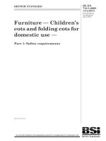
! 5.11.4.3
Test steps
Unless otherwise specified, the test shall consist of the following steps, repeating c) through f)
continuously (see Figure 3) until the end of test criteria is reached:
a) charge up to U R with constant current of 5 mA/F per cell;
b) continue charging at U R for 30 min;
c) discharge down to 0,5U R with constant current of 50 mA/F per cell;
d) pause for 15 s without charging current;
e) charge up to U R with constant current of 50 mA/F per cell;
f) hold for 15 s at constant voltage U R.
50
UR
0,5UR
0
1 cycle
Current
0
15
Current (mA/F per cell)
Voltage (V)
Voltage
15
–50
step c)
step d)
step e)
step f)
Time (s)
NOTE
step c)
IEC 2237/13
Current curve in step f) is not the specified value, but shows the result of constant voltage applied.
Figure 3 – Endurance cycling test steps
5.11.4.4
Test
The capacitor shall be connected to the charge and discharge device, then start test steps as
specified in 5.11.4.3. When the capacitor cell case has reached the test temperature, the
cooling/heating conditions are constantly adjusted throughout the test so that the capacitor
cell or the temperature of the hottest cell in a module or bank stays fixed at the test
temperature.
The capacitance and internal resistance of the capacitor can be obtained while the test step
(cycling) is in operation by monitoring voltage-time curves and analysing them. The initial
capacitance and internal resistance during cycling shall be taken after the capacitor has
reached the thermal equilibrium.
NOTE The capacitance and internal resistance measurements during cycling might differ from the initial
measurement as specified in 5.11.3 and final measurement as specified in 5.11.7 due to a different measurement
current."