Bsi bs en 61730 2 2007 + a1 2012
Bạn đang xem bản rút gọn của tài liệu. Xem và tải ngay bản đầy đủ của tài liệu tại đây (1.59 MB, 38 trang )
BRITISH STANDARD
Photovoltaic (PV)
module safety
qualification —
Part 2: Requirements for testing
ICS 27.160
BS EN
61730-2:2007
+A1:2012
BS EN 61730-2:2007+A1:2012
National foreword
This British Standard is the UK implementation of
EN 61730-2:2007+A1:2012. It is derived from IEC 61730-2:2004,
incorporating amendment 1:2011. It supersedes BS EN 61730-2:2007,
which is withdrawn.
The start and finish of text introduced or altered by amendment is
indicated in the text by tags. Tags indicating changes to IEC text carry
the number of the IEC amendment. For example, text altered by IEC
amendment 1 is indicated by !".
The CENELEC common modifications have been implemented at the
appropriate places in the text. The start and finish of each common
modification is indicated in the text by }~.
The UK participation in its preparation was entrusted to Technical
Committee GEL/82, Photovoltaic Energy Systems.
A list of organizations represented on this committee can be obtained on
request to its secretary.
This publication does not purport to include all the necessary provisions
of a contract. Users are responsible for its correct application.
Compliance with a British Standard cannot confer immunity from
legal obligations.
This British Standard was
published under the authority
of the Standards Policy and
Strategy Committee
on 31 July 2007
© The British Standards
Institution 2012. Published by
BSI Standards Limited 2012.
ISBN 978 0 580 67895 0
Amendments/corrigenda issued since publication
Date
Comments
31 May 2012
Implementation of IEC amendment 1:2011 with
CENELEC endorsement A1:2012
EUROPEAN STANDARD
EN 61730-2:2007+A1
NORME EUROPÉENNE
EUROPÄISCHE NORM
February 2012
ICS 27.160
English version
Photovoltaic (PV) module safety qualification –
Part 2: Requirements for testing
(IEC 61730-2:2004, modified)
Qualification pour la sûreté de
fonctionnement des modules
photovoltaïques (PV) –
Partie 2: Exigences pour les essais
(CEI 61730-2:2004, modifiée)
Photovoltaik (PV) -Module –
Sicherheitsqualifikation –
Teil 2: Anforderungen an die Prüfung
(IEC 61730-2:2004, modifiziert)
This European Standard was approved by CENELEC on 2006-12-01. CENELEC members are bound to comply
with the CEN/CENELEC Internal Regulations which stipulate the conditions for giving this European Standard
the status of a national standard without any alteration.
Up-to-date lists and bibliographical references concerning such national standards may be obtained on
application to the Central Secretariat or to any CENELEC member.
This European Standard exists in three official versions (English, French, German). A version in any other
language made by translation under the responsibility of a CENELEC member into its own language and notified
to the Central Secretariat has the same status as the official versions.
CENELEC members are the national electrotechnical committees of Austria, Belgium, Bulgaria, Cyprus, the
Czech Republic, Denmark, Estonia, Finland, France, Germany, Greece, Hungary, Iceland, Ireland, Italy, Latvia,
Lithuania, Luxembourg, Malta, the Netherlands, Norway, Poland, Portugal, Romania, Slovakia, Slovenia, Spain,
Sweden, Switzerland and the United Kingdom.
CENELEC
European Committee for Electrotechnical Standardization
Comité Européen de Normalisation Electrotechnique
Europäisches Komitee für Elektrotechnische Normung
Central Secretariat: rue de Stassart 35, B - 1050 Brussels
© 2007 CENELEC -
All rights of exploitation in any form and by any means reserved worldwide for CENELEC members.
Ref. No. EN 61730-2:2007 E
BS EN 61730-2:2007+A1:2012
EN 61730-2:2007+A1:2012 (E)
–2–
Foreword
The text of the International Standard IEC 61730-2:2004, prepared by IEC TC 82, Solar photovoltaic energy
systems, together with the common modifications prepared by the Technical Committee CENELEC TC 82,
Solar photovoltaic energy systems, was submitted to the formal vote and was approved by CENELEC as
EN 61730-2 on 2006-12-01.
The following dates were fixed:
–
–
latest date by which the EN has to be implemented
at national level by publication of an identical
national standard or by endorsement
(dop)
2008-02-01
latest date by which the national standards conflicting
with the EN have to be withdrawn
(dow)
2010-02-01
Annex ZA has been added by CENELEC.
__________
Endorsement notice
The text of the International Standard IEC 61730-2:2004 was approved by CENELEC as a European
Standard with agreed common modifications as given below.
__________
Foreword to amendment A1
The text of document 82/660/FDIS, future edition 1 of IEC 61730-2:2004/A1, prepared by IEC/TC 82
"Solar photovoltaic energy systems" was submitted to the IEC-CENELEC parallel vote and approved by
CENELEC as EN 61730-2:2007/A1:2012.
The following dates are fixed:
•
•
latest date by which the document has
to be implemented at national level by
publication of an identical national
standard or by endorsement
latest date by which the national
standards conflicting with the
document have to be withdrawn
(dop)
2012-09-19
(dow)
2014-12-19
Attention is drawn to the possibility that some of the elements of this document may be the subject of
patent rights. CENELEC [and/or CEN] shall not be held responsible for identifying any or all such patent
rights.
Endorsement notice
The text of the International Standard IEC 61730-2:2004/A1:2011 was approved by CENELEC as a
European Standard without any modification.
–3–
BS EN 61730-2:2007+A1:2012
EN 61730-2:2007+A1:2012 (E)
Annex ZA
(normative)
Normative references to international publications
with their corresponding European publications
The following documents, in whole or in part, are normatively referenced in this document and are
indispensable for its application. For dated references, only the edition cited applies. For undated
references, the latest edition of the referenced document (including any amendments) applies.
NOTE When an international publication has been modified by common modifications, indicated by (mod), the relevant EN/HD
applies.
Publication
Year
Title
EN/HD
Year
–
–
Glass in building - Thermally toughened soda
lime silicate safety glass –
Part 1: Definition and description
EN 12150-1
–
–
–
Datasheet and nameplate information for
photovoltaic modules
EN 50380
–
IEC 60060-1
–
High-voltage test techniques –
Part 1: General definitions and test
requirements
HD 588.1 S1
–
IEC 60068-1
–
Environmental testing –
Part 1: General and guidance
EN 60068-1
–
IEC 60243-1
–
Electrical strength of insulating materials - Test EN 60243-1
methods –
Part 1: Tests at power frequencies
–
IEC 60410
–
Sampling plans and procedures for inspection –
by attributes
–
IEC 60664-1
+ A1
+ A2
–
Insulation coordination for equipment within
low-voltage systems –
Part 1: Principles, requirements and tests
EN 60664-1
–
IEC 60904-2
–
Photovoltaic devices –
Part 2: Requirements for reference solar
devices
EN 60904-2
–
IEC 61032
–
Protection of persons and equipment by
enclosures - Probes for verification
EN 61032
–
IEC 61140
–
Protection against electric shock - Common
aspects for installation and equipment
EN 61140
–
IEC 61215
–
Crystalline silicon terrestrial photovoltaic (PV) EN 61215
modules - Design qualification and type
approval
–
IEC 61646
–
Thin-film terrestrial photovoltaic (PV) modules EN 61646
- Design qualification and type approval
–
IEC 61730-1 (mod) –
Photovoltaic (PV) module safety qualification– EN 61730-1
Part 1: Requirements for construction
–
ISO/IEC 17025
–
General requirements for the competence of
testing and calibration laboratories
ANSI/UL 514C
–
Non-metallic outlet boxes, flush device boxes –
and covers
EN ISO/IEC 17025 –
–
BS EN 61730-2:2007+A1:2012
EN 61730-2:2007+A1:2012 (E)
–4–
Publication
Year
Title
EN/HD
Year
ANSI/UL 790
–
Tests for Fire Resistance of Roof Covering
Materials
–
–
ANSI/UL 1703
–
Flat – Plate Photovoltaic Modules and Panels –
–
ANSI Z97.1
–
American National Standard for Safety
Glazing Materials Used in Buildings - Safety
Performance Specifications and Methods of
Test
–
–
–5–
BS EN 61730-2:2007+A1:2012
EN 61730-2:2007+A1:2012 (E)
CONTENTS
1
Scope and object............................................................................................................7
2
Normative references .....................................................................................................8
3
Application classes .........................................................................................................8
3.1
3.2
3.3
4
General .................................................................................................................8
Class A: General access, hazardous voltage, hazardous power applications ...........8
Class B: Restricted access, hazardous voltage, hazardous power
applications ...........................................................................................................8
3.4 Class C: Limited voltage, limited power applications ..............................................8
Test categories...............................................................................................................8
5
4.1 General .................................................................................................................8
4.2 Preconditioning tests .............................................................................................9
4.3 General inspection.................................................................................................9
4.4 Electrical shock hazard tests..................................................................................9
4.5 Fire hazard tests....................................................................................................9
4.6 Mechanical stress tests .......................................................................................10
4.7 Component tests .................................................................................................10
Application classes and their necessary test procedures ...............................................10
6
Sampling ......................................................................................................................12
7
Test report ...................................................................................................................12
8
Testing .........................................................................................................................13
9
Pass criteria ................................................................................................................. 15
10 Test procedures ...........................................................................................................15
10.1 Visual inspection MST 01.....................................................................................15
10.2 Accessibility test MST 11 .....................................................................................15
10.3 Cut susceptibility test MST 12 ..............................................................................16
10.4 Ground continuity test MST 13 .............................................................................19
10.5 Impulse voltage test MST 14 ................................................................................19
10.6 Dielectric withstand test MST 16 ..........................................................................21
10.7 Temperature test MST 21 ....................................................................................22
10.8 Fire test MST 23 ..................................................................................................24
10.9 Reverse current overload Test MST 26 ................................................................24
10.10 Module breakage test MST 32..............................................................................25
11 Component tests ..........................................................................................................30
11.1 Partial discharge-test MST 15 ..............................................................................30
11.2 Conduit bending test MST 33 ...............................................................................31
11.3 Terminal box knockout tests MST 44 ....................................................................32
Bibliography .......................................................................................................................34
BS EN 61730-2:2007+A1:2012
EN 61730-2:2007+A1:2012 (E)
–6–
Figure 1 – Test sequences ..................................................................................................14
Figure 2 – Cut susceptibility test .........................................................................................18
Figure 3 – Wave-form of the impulse voltage according to IEC 60060-1 ...............................21
Figure 4 – Impactor.............................................................................................................27
Figure 5 – Impact test frame 1 ............................................................................................28
Figure 6 – Impact test frame 2 ............................................................................................29
Figure 7 – Test fixture assembly .........................................................................................32
Table 1 – Preconditioning tests .............................................................................................9
Table 2 – General inspection test ..........................................................................................9
Table 3 – Electrical shock hazard tests .................................................................................9
Table 4 – Fire hazard tests ..................................................................................................10
Table 5 – Mechanical stress tests ........................................................................................10
Table 6 – Component tests ..................................................................................................10
Table 7 – Required tests, depending on the application class ...............................................11
Table 8 – Impulse voltage versus maximum system voltage .................................................20
Table 9 – Component temperature limits .............................................................................23
Table 10 – Bending loads....................................................................................................31
–7–
BS EN 61730-2:2007+A1:2012
EN 61730-2:2007+A1:2012 (E)
PHOTOVOLTAIC (PV) MODULE SAFETY QUALIFICATION –
Part 2: Requirements for testing
1
Scope and object
This part of }EN 61730~ describes the testing requirements for photovoltaic (PV) modules in
order to provide safe electrical and mechanical operation during their expected lifetime. Specific
topics are provided to assess the prevention of electrical shock, fire hazards, and personal injury due
to mechanical and environmental stresses. }EN 61730-1~ pertains to the particular requirements
of construction. This part of }EN 61730~ outlines the requirements of testing.
This standard attempts to define the basic requirements for various application classes of
photovoltaic modules, but it cannot be considered to encompass all national or regional
building codes. The specific requirements for marine and vehicle applications are not covered.
This standard is not applicable to modules with integrated AC inverters (AC modules).
This standard is designed so that its test sequence can co-ordinate with those of IEC 61215
or IEC 61646, so that a single set of samples may be used to perform both the safety and
performance evaluation of a photovoltaic module design.
The test-sequences of this standard are arranged in an optimal way so that tests of
IEC 61215 or IEC 61646 can be used as basic preconditioning tests.
NOTE 1 The sequence of tests required in this standard may not test for all possible safety aspects associated
with the use of PV modules in all possible applications. This standard utilizes the best sequence of tests available
at the time of its writing. There are some issues, such as the potential danger of electric shock posed by a broken
module in a high voltage system, that should be addressed by the systems design, location, restrictions on access
and maintenance procedures.
The object of this document is to provide the testing sequence intended to verify the safety of
PV modules whose construction has been assessed by }EN 61730-1~. The test sequence and
pass criteria are designed to detect the potential breakdown of internal and external
components of PV modules that would result in fire, electric shock and personal injury. The
standard defines the basic safety test requirements and additional tests that are a function of
the module end-use applications.
Test categories include general inspection, electrical shock hazard, fire hazard, mechanical
stress, and environmental stress.
NOTE 2 The additional testing requirements outlined in relevant ISO standards, or the national or local codes
which govern the installation and use of these modules in their intended locations, should be considered in addition
to the requirements contained within this document.
BS EN 61730-2:2007+A1:2012
EN 61730-2:2007+A1:2012 (E)
2
–8–
Normative references
}See Annex ZA.~
3
Application classes
3.1 General
Photovoltaic modules may be installed in many different applications. Therefore, it is
important to evaluate the potential hazards associated with those applications and to evaluate
the construction of the module accordingly.
Relevant safety requirements and necessary tests shall be performed to verify the
conformance to the requirements of that application class. This clause defines those
application classes and construction qualities required for each class.
Application classes for PV-modules are defined as follows:
3.2 Class A: General access, hazardous voltage, hazardous power applications
}Modules rated for use in this application class may be used in systems operating at greater
than 120 V DC. Modules qualified for safety through EN 61730-1 and this part of EN 61730
within this application class are considered to meet the requirements for safety class II.~
3.3 Class B: Restricted access, hazardous voltage, hazardous power applications
Modules rated for use in this application class are restricted to systems protected from public
access by fences, location, etc. Modules evaluated within this application class provide
protection by basic insulation, are considered to meet the requirements for safety class 0.
}3.4 Class C: Limited voltage
Modules rated for use in this application class are restricted to systems operating at less than
120 V DC. Modules qualified for safety through EN 61730-1 and this part of EN 61730 within
this application class are considered to meet the requirements for safety class III.
NOTE
4
Safety classes are defined within EN 61140 .~
Test categories
4.1 General
The following hazards might influence the lifetime and the safety of PV modules. In
accordance with these hazards, test procedures and criteria are described. The specific tests
to which a module will be subjected will depend on the end use application for which the
minimum tests are specified in Clause 5.
NOTE
Module safety tests are labelled MST.
Tables 1 to 6 show the origin of the required tests. For some tests, the third column shows for
information the origin of the tests, but the appropriate test requirements are given in Clauses
10 and 11. The rest of the tests are based on or identical to IEC 61215/IEC 61646, and
references to the relevant Clauses are given in the last two columns. Some of the
IEC 61215/IEC 61646-based tests were modified for }EN 61730-2 ~ and are included in Clauses
10 and 11.
–9–
BS EN 61730-2:2007+A1:2012
EN 61730-2:2007+A1:2012 (E)
4.2 Preconditioning tests
Table 1 – Preconditioning tests
Test
Title
References in
Standards
According to
IEC 61215
IEC 61646
MST 51
Thermal cycling (TC50 or TC200)
10.11
10.11
MST 52
Humidity freeze (HF10)
10.12
10.12
MST 53
Damp heat (DH1000)
10.13
10.13
MST 54
UV preconditioning test
10.10
10.10
4.3 General inspection
Table 2 – General inspection test
Test
MST 01
Title
References in
Standards
Visual inspection
According to
IEC 61215
IEC 61646
10.1
10.1
4.4 Electrical shock hazard tests
These tests are designed to assess the risk to personnel due to shock or injury because of
contact with parts of a module that are electrically energised as a result of design,
construction, or faults caused by environment or operation.
Table 3 – Electrical shock hazard tests
Test
Title
References in
Standards
According to
IEC 61215
IEC 61646
MST 11
Accessibility test
ANSI/UL 1703
MST 12
Cut susceptibility test (not required for glass
surfaces)
ANSI/UL 1703
MST 13
Ground continuity test
ANSI/UL 1703
MST 14
Impulse voltage test
MST 16
Dielectric withstand test
10.3*
10.3*
MST 17
Wet leakage current test
10.15
10.20
MST 42
Robustness of terminations test
10.14
10.14
(not required unless metal framed)
*
IEC 60664-1
The pass/fail criteria differ from those given in IEC 61215 and IEC 61646.
4.5 Fire hazard tests
These tests assess the potential fire hazard due to the operation of a module or failure of its
components.
BS EN 61730-2:2007+A1:2012
EN 61730-2:2007+A1:2012 (E)
– 10 –
Table 4 – Fire hazard tests
Test
Title
MST 21
Temperature test
MST 22
Hot-spot test
MST 23
Fire test
MST 25
Bypass diode thermal test
MST 26
Reverse current overload test
References in
Standards
According to
IEC 61215
IEC 61646
10.9
10.9
ANSI/UL 1703
ANSI/UL 790
10.18
!10.18"
ANSI/UL 1703
4.6 Mechanical stress tests
These tests are to minimise potential injury due to mechanical failure.
Table 5 – Mechanical stress tests
Test
Title
MST 32
Module breakage test
MST 34
Mechanical load test
References in
Standards
According to
IEC 61215
IEC 61646
10.16
10.16
ANSI Z97.1
4.7 Component tests
Table 6 – Component tests
Test
Title
References in
Standards
MST 15
Partial discharge test
IEC 60664-1
MST 33
Conduit bending
ANSI/UL 514C
MST 44
Terminal box knock out test
ANSI/UL 514C
5
According to
IEC 61215
IEC 61646
Application classes and their necessary test procedures
The specific tests to which a module will be subjected, depending on the application class
defined in }EN 61730-1~, is described in Table 7. The order in which the tests are carried out
shall be in accordance with Figure 1.
Some tests shall be carried out as preconditioning tests.
NOTE This test sequence has been designed so that }EN 61730-2~ can be performed in conjunction with IEC 61215
or IEC 61646. In this way, the environmental stress tests in IEC 61215 or IEC 61646 can serve as the preconditioning tests
for }EN 61730-2~.
BS EN 61730-2:2007+A1:2012
EN 61730-2:2007+A1:2012 (E)
– 11 –
Table 7 – Required tests, depending on the application class
Application class
A
B
Tests
C
Preconditioning tests:
X
X
X
MST 51 Thermal cycling (T50 or T200)
X
X
X
MST 52 Humidity freeze (10HF)
X
X
X
MST 53 Damp heat (DH1000)
X
X
X
MST 54 UV !pre-conditioning "
General inspection test:
X
X
X
MST 01 Visual inspection
Electrical shock hazard tests:
X
X
-
MST 11 Accessibility test
X
X
-
MST 12 Cut susceptibility test
X
X
X
MST 13 Ground continuity test
X
X*
-
MST 14 Impulse voltage test
X
X*
-
MST 16 Dielectric withstand test
X
X
-
MST 17 Wet leakage current test
X
X
X
MST 42 Robustness of terminations test
Fire hazard tests:
X
X
X
MST 21 Temperature test
X
X
X
MST 22 Hot spot test
-
-
Fire test ~
X
X
-
MST 26 Reverse current overload test
X
-
X
MST 32 Module breakage test
X
X
X
MST 34 Mechanical load test
}X**
Mechanical stress tests:
Component tests:
X
-
-
MST 15 Partial discharge test
X
X
X
-
MST 33 Conduit bending
X
X
MST 44 Terminal box knockout test
X
Test required.
-
Test needs not be carried out.
*
Different test levels for application classes A and B.
} ** A European fire test is under consideration.~
BS EN 61730-2:2007+A1:2012
EN 61730-2:2007+A1:2012 (E)
6
– 12 –
Sampling
Six modules and a laminate 1 (a module without frame) for safety testing (plus spares as
desired) and additional modules as required for the fire-test shall be taken at random from a
production batch or batches, in accordance with the procedure given in IEC 60410. The
modules shall have been manufactured from specified materials and components in
accordance with the relevant drawings and process sheets and have been subjected to the
manufacturer's normal inspection, quality control and production acceptance procedures. The
modules shall be complete in every detail and shall be accompanied by the manufacturer's
handling, mounting and connection instructions, including the maximum permissible system
voltage.
When the modules to be tested are prototypes of a new design and not from production, this
fact shall be noted in the test report (see Clause 7).
7
Test report
The results shall be laid down in a test report according to ISO/IEC 17025. The results shall
be reported, normally in a test report and shall include all the information requested by the
client and necessary to the interpretation of the test and all information required by the
method used:
a) a title;
b) name and address of the test laboratory and location where the tests were carried out;
c) unique identification of the certification or report and of each page;
d) name and address of client, where appropriate;
e) description and identification of the item tested;
f)
characterization and condition of the test item;
g) date of receipt of test item and date(s) of test, where appropriate;
h) identification of test method used;
i)
reference to sampling procedure, where relevant;
j)
any deviations from, additions to or exclusions from the test method, and any other
information relevant to a specific tests, such as environmental conditions;
k) measurements, examinations and derived results supported by tables, graphs, sketches
and photographs as appropriate including maximum systems voltage, safety class,
mounting technique and any failures observed;
l)
a statement indicating whether the impulse voltage test was performed on module or
laminate;
m) a statement of the estimated uncertainty of the test results (where relevant);
n) a signature and title, or equivalent identification of the person(s) accepting responsibility
for the content of the certificate or report, and the date of issue;
o) where relevant, a statement to the effect that the results relate only to the items tested;
p) a statement that the certificate or report shall not be reproduced except in full, without the
written approval of the laboratory.
A copy of this report shall be kept by the manufacturer for reference purposes.
—————————
1 If the module is only used with frame and the frame is an essential part to fulfil the isolation requirement, the
laminate can be replaced by a module.
– 13 –
8
BS EN 61730-2:2007+A1:2012
EN 61730-2:2007+A1:2012 (E)
Testing
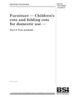
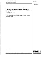
The modules shall be divided into groups and subjected to the safety tests shown in Figure 1,
carried out in the order specified. The modules shall be selected such that the preconditioning
tests of 4.2 are met. Each box in Figure 1 refers to the corresponding subclause in this part of
}EN 61730.~
NOTE Spare modules may be included in the safety test program provided that they have been appropriately
environmentally tested to meet the necessary prerequisites.
Test procedures and criteria, including initial and final measurements where necessary, are
detailed in Clauses 10 and 11. Some tests are identical to tests in IEC 61215/IEC 61646 and
are detailed in Clause 4 instead. In carrying out these tests, the tester shall strictly observe
the manufacturer's handling, mounting, and connection instructions.
BS EN 61730-2:2007+A1:2012
EN 61730-2:2007+A1:2012 (E)
– 14 –
Indicates change from
Edition 1 are near the red
bar
!
Module safety test MST
IEC 61730
7 modules or
6 modules and 1 laminate
IEC 61215
IEC 61646
01
Module performance test MPT
17
The numbers in each box are references to final
measurements, that are to be performed after
MST or MPT (if required). In this example:
01
17
1 module
Control
Visual inspection
MST 01
= Module safety test MST 01
= Module safety test MST 17
3 modules
1 laminate
1 module
Number of
modules depends
on the module size
Component tests
Performance test
(IEC 61215,
IEC 61646)
11 pieces
of foil
1 module
1 piece
of
junction
box
Dielectric withstand
test
MST 16
Test on
6 knock
outs
Ground continuity
test
MST 13
Module breakage test
MST 32
Fire test
MST 23
Partial discharge
test
MST 15
Accessibility
test
MST 11
Conduit bending
test
MST 33
Wet leakage current
test
MST 17
1 module
UV pre-conditioning test
MST 54
01
01
16
16
laminate
(module)
16
Humidity freeze test
MST 52
01
16
Wet leakage current
test
MST 17
Thermal cycling test
50 cycles
MST 51b
01
Thermal cycling test
200 cycles
MST 51a
Damp heat
Heat test
Test
1000
1
000hh
MST 53
01
16
16
Mechanical load
test
MST 34
01
Bypass diode
thermal test
MST 25
01
Impulse voltage
test
MST 14
17
01
16
Robustness of
terminations test
MST 42
01
Terminal box
knock out test
MST 44
1 module
1 laminate (module)
1 module
16
17
Hot-spot
test
MST 22
01
16
17
Temperature
test
MST 21
16
Cut susceptibility
test
MST 12
01
13
16
Reverse current
overload test
MST 26
17
17
Ground continuity
test
MST 13
Accessibility test
MST 11
Visual inspection
MST 01
Figure 1 – Tes t sequences
IEC 2549/11
"
– 15 –
9
BS EN 61730-2:2007+A1:2012
EN 61730-2:2007+A1:2012 (E)
Pass criteria
The module product under evaluation shall be judged to have passed the safety qualification
test, if the test samples meet all of the criteria of each individual test.
If any module does not meet these test criteria, the module product under evaluation shall be
deemed not to have met the safety test requirements.
NOTE
The nature of the failure will determine the extent of re-testing requirements.
10 Test procedures
10.1 Visual inspection MST 01
10.1.1
Purpose
To detect any visual defects in the module.
10.1.2
Procedure
This test is identical with 10.1 from IEC 61215/IEC 61646 with the additional inspection
criteria of
–
any other conditions which may affect safety;
–
markings not consistent with Clause 11 of }EN 61730-1~ .
Make note of and/or photograph the nature and position of any cracks, bubbles or
delaminations, etc. which may worsen and adversely affect the module safety in subsequent
tests. Visual conditions other than the major defects listed below are acceptable for the
purpose of safety test approval.
10.1.3
Pass criteria
For the purpose of the safety test approval, the following are considered to be major visual
defects:
a) broken, cracked, or torn external surfaces;
b) bent or misaligned external surfaces, including superstrates, substrates, frames and
junction boxes to the extent that the safety of the module would be impaired;
c) bubbles or delaminations forming a continuous path between any part of the electrical
circuit and the edge of the module, or which exhibited significant growth during the testing
and would, if testing were continued, reach such a condition;
d) evidence of any molten or burned encapsulant, back sheet, diode or active PV component;
e) loss of mechanical integrity to the extent that the safety of the installation and operation of
the module would be impaired;
f)
markings not complying with Clause 12 of }EN 61730-1~ .
10.2 Accessibility test MST 11
10.2.1
Purpose
To determine if uninsulated electrical connections represent a shock hazard to personnel.
BS EN 61730-2:2007+A1:2012
EN 61730-2:2007+A1:2012 (E)
10.2.2
– 16 –
Apparatus
The apparatus is as follows:
a) A cylindrical test fixture Type 11 according to Figure 7 of IEC 61032 .
b) An ohmmeter or continuity tester.
10.2.3
Procedure
The procedure is as follows:
a) Mount and wire the test module as recommended by the manufacturer.
b) Attach the ohmmeter or continuity tester to the module electric circuit and to the test
fixture.
c) Remove all covers, plugs and connections from the module that can be removed without
using a tool.
d) Probe with the test fixture in and around all electrical connectors, plugs, junction boxes
and any other areas where the electrical circuit of the module may be accessible.
e) Monitor the ohmmeter or continuity tester during the probing to determine if the test fixture
makes electrical contact to the module electric circuitry.
10.2.4
Final measurements
None.
10.2.5
Requirements
At no time during the test shall there be less than 1 MΩ resistance between the test fixture
and the module electric circuit.
10.2.6
Pass criteria
At no time during the test shall the probe contact any live electrical part. This test is
performed at the beginning and the end of the sequence according to Figure 1, but also can
be used at any time during the test sequence if there is any reason to believe that active
electric circuitry has been exposed by one of the other tests.
10.3 Cut susceptibility test MST 12
10.3.1
Purpose
To determine whether any front and rear surfaces of the module made of polymeric materials
are capable of withstanding routine handling during installation and maintenance without
exposing personnel to the danger of electric shock. !Text deleted"
10.3.2
Apparatus
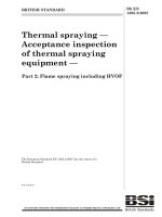
A test fixture as shown in Figure 2, designed to draw a defined shaped object, a 0,64 mm ±
0,05 mm thick carbon steel blade (for example the back of a hacksaw blade) over the surface
of the module with an applied force of 8,9 N ± 0,5 N.
– 17 –
10.3.3
BS EN 61730-2:2007+A1:2012
EN 61730-2:2007+A1:2012 (E)
Procedure
The procedure is as follows:
a) Position the module horizontally with the front surface facing upward.
b) The test fixture is to be placed on the surface for 1 min and then drawn across the surface
of the module at a speed of (150 ± 30) mm/s.
Repeat the procedure five times in different directions.
c) Repeat a) and b) for the rear surface of the module.
10.3.4
Final measurements
Repeat MST 01, !Text deleted", MST 16 and MST 17.
10.3.5
Pass criteria
The pass criteria are as follows:
a) No visual evidence that the superstrate or substrate surfaces have been cut, exposing the
active circuitry of the module.
b) !Text deleted" MST 16, MST 17 shall meet the same requirements as for the initial
measurements.
BS EN 61730-2:2007+A1:2012
EN 61730-2:2007+A1:2012 (E)
– 18 –
A
140°
B
Q
Test point
carbon steel strip
(i.e. hacksaw
blade)
C
90°
IEC 1358/04
Key
A
150 mm from axis to center of weight.
B
170 mm from axis to test point.
C
Test point – 0,64 mm thick steel strip.
Q
Total force exerted at test point Q: 8,9 N
Figure 2 – Cut susceptibility test
– 19 –
BS EN 61730-2:2007+A1:2012
EN 61730-2:2007+A1:2012 (E)
10.4 Ground continuity test MST 13
10.4.1
Purpose
To demonstrate that there is a conductive path between all exposed conductive surfaces of
the module, so that the exposed conductive surfaces can be adequately grounded in a PV
system. This test is required only if the module has exposed conductive parts such as a metal
frame or a metallic junction box.
10.4.2
Apparatus
The apparatus is as follows:
a) A constant current supply capable of producing a current that is 2,5 times the maximum
over-current protection rating of the module under test. See MST 26.
b) A suitable voltmeter.
NOTE 1 According to }EN 61730-1~ the maximum over-current protection rating has to be provided by the
manufacturer.
}NOTE 2 The maximum over-current protection rating of a module can be interpreted as the module series fuse
rating. A series fuse may be required in the installation of PV arrays. According to Subclause 12.2 of EN 61730-1
the maximum over-current protection rating has to be provided by the manufacturer.
NOTE 3
10.4.3
A procedure for determination of maximum reverse current is described in EN 50380.~
Procedure
The procedure is as follows:
a) Select the manufacturer’s designated grounding point and recommended grounding
connection. Attach to one terminal of the constant current supply.
b) Select an adjacent (connected) exposed conductive component with the greatest physical
displacement from the grounding point, and attach to the other terminal of the current
supply.
c) Attach the voltmeter to the two conductive components attached to the current supply in
proximity to the current leads.
d) Apply a current 2,5 times ± 10 % of the maximum over-current protection rating of the
module for a minimum of 2 min.
e) Measure the applied current and the resultant voltage drop.
f)
Reduce the current to zero.
g) Repeat the test on one additional frame component.
10.4.4
Final measurements
None.
10.4.5
Pass criteria
The resistance between the selected exposed conductive component and each other
conductive component of the module shall be less than 0,1 Ω.
10.5 Impulse voltage test MST 14
10.5.1
Purpose
To verify the capability of the solid insulation of the module to withstand over-voltages of
atmospheric origin. It also covers over-voltages due to switching of low-voltage equipment.
BS EN 61730-2:2007+A1:2012
EN 61730-2:2007+A1:2012 (E)
– 20 –
NOTE If the PV module is not going to be sold without frame, the impulse voltage test should be done with the
module framed.
10.5.2
Apparatus
The apparatus is as follows:
a) Impulse voltage generator.
b) Oscilloscope.
10.5.3
Procedures
For the purposes of test reproducibility, this test is conducted under the conditions of room temperature
and relative humidity of less than 75 %. !The impulse test shall be performed in accordance with
IEC 60060-1." The procedure is as follows:
a) Cover the whole module with a copper foil. Connect the foil to the negative terminal of the
impulse voltage generator.
b) Connect the shorted output terminals of the module to the positive terminal of the impulse
voltage generator.
Specification of the foil:
1) Thickness copper 0,03 mm to 0,05 mm.
2
2) !Conducting glue (resistance < 1 Ω, measuring area: 625 mm )."
3) Total thickness 0,05 mm to 0,07 mm.
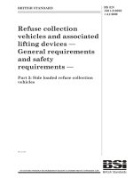
c) With no illumination, apply the surge impulse voltage given in Table 8 with a waveform as shown
in Figure 3 by the impulse voltage generator. !The waveform of the pulse shall be observed
by an oscilloscope with the module connected and the rise time and the pulse duration shall be
checked for each test."
NOTE 1 According to 2.2.2.1.1 of IEC 60664-1, modules belong to the over-voltage category III. The testlevel has been reduced by one step because systems are normally equipped with over-voltage protection
devices. On the other hand, to verify reinforced insulation (as required for application class A and safety class
II), the level for application class A has been increased by one step.
Table 8 – Impulse voltage versus maximum system voltage
Maximum system voltage
V
NOTE 2
Impulse voltage
Application class A
V
Application class B
V
100
1 500
800
150
2 500
1 500
300
4 000
2 500
600
6 000
4 000
1 000
8 000
6 000
Linear interpolation is allowed for intermediate values of maximum system voltage.
d) Three successive pulses shall be applied.
e) Change the polarity of the terminals of the pulse generator and apply three successive
pulses.
– 21 –
10.5.4
BS EN 61730-2:2007+A1:2012
EN 61730-2:2007+A1:2012 (E)
Final measurement
Repeat MST 01 visual inspection.
10.5.5
Pass criteria
The pass criteria are as follows:
a) No evidence of dielectric breakdown or surface tracking of the module is observed during
the test.
b) No evidence of major visual defects as defined in 10.1.
Voltage
1,0
0,9
B
0,5
0,3
A
0
01
T’
Time
T
T1
T2
T1 = 1,2 μs ± 30 %
T2 = 50 μs ± 20 %
IEC 1359/04
NOTE The parameter 0 1 is the start point of the impulse voltage. In a diagram with linear time scale this is the
intersection point of the time axis and the line defined by points A and B.
Figure 3 – Wave-form of the impulse voltage according to IEC 60060-1
10.6 Dielectric withstand test MST 16
10.6.1
Purpose
To determine whether or not the module is sufficiently well insulated between current carrying
parts and the frame or the outside world.
The test shall be made on modules at ambient temperature of the surrounding atmosphere
(see IEC 60068-1) and in a relative humidity not exceeding 75 %.
10.6.2
Procedure
This test is identical with test 10.3 from IEC 61215/IEC 61646 with test levels depending on
the application class and the maximum system voltage.
The maximum test voltage shall be equal to 2 000 V plus four times the maximum system
voltage for application-class A and equal to 1 000 V plus two times the maximum system
voltage for application-class B.
BS EN 61730-2:2007+A1:2012
EN 61730-2:2007+A1:2012 (E)
10.6.3
– 22 –
Pass criteria
See IEC 61215/IEC 61646.
10.7 Temperature test MST 21
10.7.1
Purpose
This temperature test is designed to determine the maximum reference temperatures for
various components and materials used to construct the module, in order to establish the
suitability of their use.
10.7.2
Test conditions
The ambient temperature during the test may be in the range of 20 °C to 55 °C.
The irradiance during the test shall be no less than 700 W/m 2 measured coplanar with the
module by a calibrated device with the accuracy to ±5 % in accordance with IEC 60904-2 and
IEC 60904-6. All data shall be taken at wind-speeds of less than 1 m/s.
10.7.3
Procedure
The module under test shall be mounted on a platform constructed of wood, pressed wood, or
plywood, approximately 19 mm thick. The platform is to be painted flat black on the side
facing the test sample. The platform shall extend at least 60 cm beyond the module on all
sides.
The module under test shall be mounted to the platform in accordance with the
manufacturer’s installation instructions. If the instructions offer more than one option, the
option providing the worst-case shall be used. If no indications have been provided, the test
module shall be mounted directly to the platform.
The module component temperatures shall be measured by a calibrated device or system,
with an maximum uncertainty of ±2 °C.
The module is to be operated under both open- and short-circuit conditions, and stabilised
temperature data for each test location shall be collected in each condition. Thermal stability
has been attained when three successive readings, taken 5 min apart, indicate a change in
temperature of less than ±1 °C.
The measured component temperatures (T obs ) shall be normalised by the addition of the
difference between the 40 °C reference ambient and the measured ambient temperature
(T amb ) according to the equation Tcon = T obs + (40 – Tamb ) ⋅ T con is the normalised
temperature.
If an unacceptable performance is encountered during the temperature test and the
performance is attributed to a test condition that although within the limits specified may be
considered more severe than necessary; for example an ambient temperature near the limits
allowed, the test may be conducted under conditions closer to the norm.
If the irradiance is other than 1 000 W/m 2 , temperatures for more than two irradiance levels
with at least 80 W/m 2 apart between the levels shall be determined, and a quadratic
extrapolation conducted to determine the temperature under 1 000 W/m 2 irradiance.
BS EN 61730-2:2007+A1:2012
EN 61730-2:2007+A1:2012 (E)
– 23 –
Typical measurement points include:
•
Module superstrate above the centre cell.
•
Module substrate below the centre cell.
•
Terminal enclosure interior surface.
•
Terminal enclosure interior air space.
•
Field wiring terminals.
•
Insulation of the field wiring leads.
•
External connector bodies (if so equipped).
•
Diode bodies (if so equipped).
NOTE Due to the many possible variations in construction, more than one data gathering point for each cited
location may be used, at the discretion of the test laboratory.
10.7.4
Requirements
The requirements are as follows:
a) No measured temperatures exceed any of the temperature limits of surfaces, materials, or
components, as described in Table 9; or
b) No creeping, distortion, sagging, charring or similar damage to any part of the module, as
indicated in 10.1.
Table 9 – Component temperature limits
Temperature limits
°C
Part, material or component
Insulating materials:
c)
Polymeric
a)
Fiber
90
Laminated phenolic composition
125
Molded phenolic composition
150
Field wiring terminals, metal parts
30 above ambient
Field wiring compartments that wires may contact
d)
a)
or
Insulated conductors
d)
Mounting surface (frame) and adjacent structural members
90
d)
, whichever is greater, or
b)
a)
The material’s relative thermal index (RTI), less 20 °C.
b)
If a marking is provided to state the minimum temperature rating of the conductors to be used, the terminals at
points within a wiring compartment may exceed the value specified but shall not attain a temperature higher
than 90 °C.
c)
Higher temperatures than specified are acceptable if it can be determined that the higher temperatures will not
cause a risk of fire or electric shock.
d)
Temperatures measured on insulated conductors shall not exceed the rated temperature of the conductor.