Bsi bs en 61508 5 2010
Bạn đang xem bản rút gọn của tài liệu. Xem và tải ngay bản đầy đủ của tài liệu tại đây (1.65 MB, 50 trang )
Licensed Copy: Science & Technology Facilities Council, 25/08/2010 10:15, Uncontrolled Copy, (c) BSI
BS EN 61508-5:2010
BSI Standards Publication
Functional safety of electrical/
electronic/programmable
electronic safety related
systems
Part 5: Examples of methods for the determination
of safety integrity levels
NO COPYING WITHOUT BSI PERMISSION EXCEPT AS PERMITTED BY COPYRIGHT LAW
raising standards worldwide™
BRITISH STANDARD
Licensed Copy: Science & Technology Facilities Council, 25/08/2010 10:15, Uncontrolled Copy, (c) BSI
BS EN 61508-5:2010
National foreword
This British Standard is the UK implementation of EN 61508-5:2010. It is
identical to IEC 61508-5:2010. It supersedes BS EN 61508-5:2002 which is
withdrawn.
The UK participation in its preparation was entrusted by Technical Committee
GEL/65, Measurement and control, to Subcommittee GEL/65/1, System
considerations.
A list of organizations represented on this committee can be obtained on
request to its secretary.
This publication does not purport to include all the necessary provisions of a
contract. Users are responsible for its correct application.
© BSI 2010
ISBN 978 0 580 65449 7
ICS 13.260; 25.040.40; 29.020
Compliance with a British Standard cannot confer immunity from
legal obligations.
This British Standard was published under the authority of the Standards
Policy and Strategy Committee on 30 June 2010.
Amendments issued since publication
Amd. No.
Date
Text affected
Licensed Copy: Science & Technology Facilities Council, 25/08/2010 10:15, Uncontrolled Copy, (c) BSI
BS EN 61508-5:2010
EUROPEAN STANDARD
EN 61508-5
NORME EUROPÉENNE
May 2010
EUROPÄISCHE NORM
ICS 25.040.40
Supersedes EN 61508-5:2001
English version
Functional safety of electrical/electronic/programmable electronic safetyrelated systems Part 5: Examples of methods for the determination of safety integrity
levels
(IEC 61508-5:2010)
Sécurité fonctionnelle des systèmes
électriques/électroniques/électroniques
programmables relatifs à la sécurité Partie 5: Exemples de méthodes
pour la détermination des niveaux
d'intégrité de sécurité
(CEI 61508-5:2010)
Funktionale Sicherheit sicherheitsbezogener
elektrischer/elektronischer/programmierbarer
elektronischer Systeme Teil 5: Beispiele zur Ermittlung der Stufe
der Sicherheitsintegrität (safety integrety
level)
(IEC 61508-5:2010)
This European Standard was approved by CENELEC on 2010-05-01. CENELEC members are bound to comply
with the CEN/CENELEC Internal Regulations which stipulate the conditions for giving this European Standard
the status of a national standard without any alteration.
Up-to-date lists and bibliographical references concerning such national standards may be obtained on
application to the Central Secretariat or to any CENELEC member.
This European Standard exists in three official versions (English, French, German). A version in any other
language made by translation under the responsibility of a CENELEC member into its own language and notified
to the Central Secretariat has the same status as the official versions.
CENELEC members are the national electrotechnical committees of Austria, Belgium, Bulgaria, Croatia, Cyprus,
the Czech Republic, Denmark, Estonia, Finland, France, Germany, Greece, Hungary, Iceland, Ireland, Italy,
Latvia, Lithuania, Luxembourg, Malta, the Netherlands, Norway, Poland, Portugal, Romania, Slovakia, Slovenia,
Spain, Sweden, Switzerland and the United Kingdom.
CENELEC
European Committee for Electrotechnical Standardization
Comité Européen de Normalisation Electrotechnique
Europäisches Komitee für Elektrotechnische Normung
Management Centre: Avenue Marnix 17, B - 1000 Brussels
© 2010 CENELEC -
All rights of exploitation in any form and by any means reserved worldwide for CENELEC members.
Ref. No. EN 61508-5:2010 E
Licensed Copy: Science & Technology Facilities Council, 25/08/2010 10:15, Uncontrolled Copy, (c) BSI
BS EN 61508-5:2010
EN 61508-5:2010
-2-
Foreword
The text of document 65A/552/FDIS, future edition 2 of IEC 61508-5, prepared by SC 65A, System
aspects, of IEC TC 65, Industrial-process measurement, control and automation, was submitted to the
IEC-CENELEC parallel vote and was approved by CENELEC as EN 61508-5 on 2010-05-01.
This European Standard supersedes EN 61508-5:2001.
Attention is drawn to the possibility that some of the elements of this document may be the subject of
patent rights. CEN and CENELEC shall not be held responsible for identifying any or all such patent
rights.
The following dates were fixed:
– latest date by which the EN has to be implemented
at national level by publication of an identical
national standard or by endorsement
(dop)
2011-02-01
– latest date by which the national standards conflicting
with the EN have to be withdrawn
(dow)
2013-05-01
Annex ZA has been added by CENELEC.
__________
Endorsement notice
The text of the International Standard IEC 61508-5:2010 was approved by CENELEC as a European
Standard without any modification.
In the official version, for Bibliography, the following notes have to be added for the standards indicated:
[1] IEC 61511 series
NOTE Harmonized in EN 61511 series (not modified).
[2] IEC 62061
NOTE Harmonized as EN 62061.
[3] IEC 61800-5-2
NOTE Harmonized as EN 61800-5-2.
[9] ISO/IEC 31010
NOTE Harmonized as EN 31010.
[10] ISO 10418:2003
NOTE Harmonized as EN 10418:2003 (not modified).
[12] ISO 13849-1:2006
NOTE Harmonized as EN ISO 13849-1:2006 (not modified).
[13] IEC 60601 series
NOTE Harmonized in EN 60601 series (partially modified).
[14] IEC 61508-2
NOTE Harmonized as EN 61508-2.
[15] IEC 61508-3
NOTE Harmonized as EN 61508-3.
[16] IEC 61508-6
NOTE Harmonized as EN 61508-6.
[17] IEC 61508-7
NOTE Harmonized as EN 61508-7.
[18] IEC 61511-1
NOTE Harmonized as EN 61511-1.
__________
Licensed Copy: Science & Technology Facilities Council, 25/08/2010 10:15, Uncontrolled Copy, (c) BSI
-3-
BS EN 61508-5:2010
EN 61508-5:2010
Annex ZA
(normative)
Normative references to international publications
with their corresponding European publications
The following referenced documents are indispensable for the application of this document. For dated
references, only the edition cited applies. For undated references, the latest edition of the referenced
document (including any amendments) applies.
NOTE When an international publication has been modified by common modifications, indicated by (mod), the relevant EN/HD
applies.
Publication
Year
Title
IEC 61508-1
2010
Functional safety of
EN 61508-1
electrical/electronic/programmable electronic
safety-related systems Part 1: General requirements
2010
IEC 61508-4
2010
Functional safety of
EN 61508-4
electrical/electronic/programmable electronic
safety-related systems Part 4: Definitions and abbreviations
2010
EN/HD
Year
Licensed Copy: Science & Technology Facilities Council, 25/08/2010 10:15, Uncontrolled Copy, (c) BSI
BS EN 61508-5:2010
–2–
61508-5 © IEC:2010
CONTENTS
INTRODUCTION.....................................................................................................................5
1
Scope ...............................................................................................................................7
2
Normative references .......................................................................................................9
3
Definitions and abbreviations............................................................................................9
Annex A (informative) Risk and safety integrity – General concepts ..................................... 10
Annex B (informative) Selection of methods for determining safety integrity level
requirements......................................................................................................................... 21
Annex C (informative) ALARP and tolerable risk concepts ................................................... 24
Annex D (informative) Determination of safety integrity levels – A quantitative method ........ 27
Annex E (informative) Determination of safety integrity levels – Risk graph methods ........... 30
Annex F (informative) Semi-quantitative method using layer of protection analysis
(LOPA) ................................................................................................................................. 38
Annex G (informative) Determination of safety integrity levels – A qualitative method –
hazardous event severity matrix............................................................................................ 44
Bibliography.......................................................................................................................... 46
Figure 1 – Overall framework of the IEC 61508 series ............................................................8
Figure A.1 – Risk reduction – general concepts (low demand mode of operation) ................. 14
Figure A.2 – Risk and safety integrity concept ...................................................................... 14
Figure A.3 – Risk diagram for high demand applications ....................................................... 15
Figure A.4 – Risk diagram for continuous mode operation .................................................... 16
Figure A.5 – Illustration of common cause failures (CCFs) of elements in the EUC
control system and elements in the E/E/PE safety-related system......................................... 17
Figure A.6 – Common cause between two E/E/PE safety-related systems ............................ 18
Figure A.7 – Allocation of safety requirements to the E/E/PE safety-related systems,
and other risk reduction measures ........................................................................................ 20
Figure C.1 – Tolerable risk and ALARP................................................................................. 25
Figure D.1 – Safety integrity allocation – example for safety-related protection system ......... 29
Figure E.1 – Risk Graph: general scheme ............................................................................. 33
Figure E.2 – Risk graph – example (illustrates general principles only) ................................. 34
Figure G.1 – Hazardous event severity matrix – example (illustrates general principles
only) ..................................................................................................................................... 45
Table C.1 – Example of risk classification of accidents ......................................................... 26
Table C.2 – Interpretation of risk classes .............................................................................. 26
Table E.1 – Example of data relating to risk graph (Figure E.2)............................................. 35
Table E.2 – Example of calibration of the general purpose risk graph ................................... 36
Table F.1 – LOPA report ....................................................................................................... 40
Licensed Copy: Science & Technology Facilities Council, 25/08/2010 10:15, Uncontrolled Copy, (c) BSI
BS EN 61508-5:2010
61508-5 © IEC:2010
–5–
INTRODUCTION
Systems comprised of electrical and/or electronic elements have been used for many years to
perform safety functions in most application sectors. Computer-based systems (generically
referred to as programmable electronic systems) are being used in all application sectors to
perform non-safety functions and, increasingly, to perform safety functions. If computer
system technology is to be effectively and safely exploited, it is essential that those
responsible for making decisions have sufficient guidance on the safety aspects on which to
make these decisions.
This International Standard sets out a generic approach for all safety lifecycle activities for
systems comprised of electrical and/or electronic and/or programmable electronic (E/E/PE)
elements that are used to perform safety functions. This unified approach has been adopted
in order that a rational and consistent technical policy be developed for all electrically-based
safety-related systems. A major objective is to facilitate the development of product and
application sector international standards based on the IEC 61508 series.
NOTE 1 Examples of product and application sector international standards based on the IEC 61508 series are
given in the Bibliography (see references [1], [2] and [3]).
In most situations, safety is achieved by a number of systems which rely on many
technologies (for example mechanical, hydraulic, pneumatic, electrical, electronic, programmable
electronic). Any safety strategy must therefore consider not only all the elements within an
individual system (for example sensors, controlling devices and actuators) but also all the
safety-related systems making up the total combination of safety-related systems. Therefore,
while this International Standard is concerned with E/E/PE safety-related systems, it may also
provide a framework within which safety-related systems based on other technologies may be
considered.
It is recognized that there is a great variety of applications using E/E/PE safety-related
systems in a variety of application sectors and covering a wide range of complexity, hazard
and risk potentials. In any particular application, the required safety measures will be
dependent on many factors specific to the application. This International Standard, by being
generic, will enable such measures to be formulated in future product and application sector
international standards and in revisions of those that already exist.
This International Standard
–
considers all relevant overall, E/E/PE system and software safety lifecycle phases (for
example, from initial concept, though design, implementation, operation and maintenance
to decommissioning) when E/E/PE systems are used to perform safety functions;
–
has been conceived with a rapidly developing technology in mind; the framework is
sufficiently robust and comprehensive to cater for future developments;
–
enables product and application sector international standards, dealing with E/E/PE
safety-related systems, to be developed; the development of product and application
sector international standards, within the framework of this standard, should lead to a high
level of consistency (for example, of underlying principles, terminology etc.) both within
application sectors and across application sectors; this will have both safety and economic
benefits;
–
provides a method for the development of the safety requirements specification necessary
to achieve the required functional safety for E/E/PE safety-related systems;
–
adopts a risk-based approach by which the safety integrity requirements can be
determined;
–
introduces safety integrity levels for specifying the target level of safety integrity for the
safety functions to be implemented by the E/E/PE safety-related systems;
NOTE 2 The standard does not specify the safety integrity level requirements for any safety function, nor does it
mandate how the safety integrity level is determined. Instead it provides a risk-based conceptual framework and
example techniques.
Licensed Copy: Science & Technology Facilities Council, 25/08/2010 10:15, Uncontrolled Copy, (c) BSI
BS EN 61508-5:2010
–6–
61508-5 © IEC:2010
–
sets target failure measures for safety functions carried out by E/E/PE safety-related
systems, which are linked to the safety integrity levels;
–
sets a lower limit on the target failure measures for a safety function carried out by a
single E/E/PE safety-related system. For E/E/PE safety-related systems operating in
–
a low demand mode of operation, the lower limit is set at an average probability of a
dangerous failure on demand of 10 –5 ;
–
a high demand or a continuous mode of operation, the lower limit is set at an average
frequency of a dangerous failure of 10 –9 [h -1 ];
NOTE 3
A single E/E/PE safety-related system does not necessarily mean a single-channel architecture.
NOTE 4 It may be possible to achieve designs of safety-related systems with lower values for the target safety
integrity for non-complex systems, but these limits are considered to represent what can be achieved for relatively
complex systems (for example programmable electronic safety-related systems) at the present time.
–
sets requirements for the avoidance and control of systematic faults, which are based on
experience and judgement from practical experience gained in industry. Even though the
probability of occurrence of systematic failures cannot in general be quantified the
standard does, however, allow a claim to be made, for a specified safety function, that the
target failure measure associated with the safety function can be considered to be
achieved if all the requirements in the standard have been met;
–
introduces systematic capability which applies to an element with respect to its confidence
that the systematic safety integrity meets the requirements of the specified safety integrity
level;
–
adopts a broad range of principles, techniques and measures to achieve functional safety
for E/E/PE safety-related systems, but does not explicitly use the concept of fail safe
However, the concepts of “fail safe” and “inherently safe” principles may be applicable and
adoption of such concepts is acceptable providing the requirements of the relevant
clauses in the standard are met.
Licensed Copy: Science & Technology Facilities Council, 25/08/2010 10:15, Uncontrolled Copy, (c) BSI
BS EN 61508-5:2010
61508-5 © IEC:2010
–7–
FUNCTIONAL SAFETY OF ELECTRICAL/ELECTRONIC/
PROGRAMMABLE ELECTRONIC SAFETY-RELATED SYSTEMS –
Part 5: Examples of methods for the determination
of safety integrity levels
1
1.1
Scope
This part of IEC 61508 provides information on
–
the underlying concepts of risk and the relationship of risk to safety integrity (see Annex
A);
–
a number of methods that will enable the safety integrity levels for the E/E/PE safetyrelated systems to be determined (see Annexes C, D, E, F and G).
The method selected will depend upon the application sector and the specific circumstances
under consideration. Annexes C, D, E, F and G illustrate quantitative and qualitative
approaches and have been simplified in order to illustrate the underlying principles. These
annexes have been included to illustrate the general principles of a number of methods but do
not provide a definitive account. Those intending to apply the methods indicated in these
annexes should consult the source material referenced.
NOTE For more information on the approaches illustrated in Annexes B, and E, see references [5] and [8] in the
Bibliography. See also reference [6] in the Bibliography for a description of an additional approach.
1.2 IEC 61508-1, IEC 61508-2, IEC 61508-3 and IEC 61508-4 are basic safety publications,
although this status does not apply in the context of low complexity E/E/PE safety-related
systems (see 3.4.3 of IEC 61508-4). As basic safety publications, they are intended for use by
technical committees in the preparation of standards in accordance with the principles
contained in IEC Guide 104 and ISO/IEC Guide 51. IEC 61508-1, IEC 61508-2, IEC 61508-3
and IEC 61508-4 are also intended for use as stand-alone publications. The horizontal safety
function of this international standard does not apply to medical equipment in compliance with
the IEC 60601 series.
1.3 One of the responsibilities of a technical committee is, wherever applicable, to make use
of basic safety publications in the preparation of its publications. In this context, the
requirements, test methods or test conditions of this basic safety publication will not apply
unless specifically referred to or included in the publications prepared by those technical
committees.
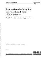
1.4 Figure 1 shows the overall framework of the IEC 61508 series and indicates the role that
IEC 61508-5 plays in the achievement of functional safety for E/E/PE safety-related systems.
Licensed Copy: Science & Technology Facilities Council, 25/08/2010 10:15, Uncontrolled Copy, (c) BSI
BS EN 61508-5:2010
61508-5 © IEC:2010
–8–
Technical Requirements
Other Requirements
Part 4
Part 1
Development of the overall
safety requirements
(concept, scope, defi nition,
hazard and r isk analysis)
7.1 to 7.5
Definitions &
abbreviations
Part 5
Example of methods
for the deter mination
of safety integri ty
levels
Part 1
All ocation of the safety requirements
to the E/E/PE safety-related systems
7.6
Part 1
Documentation
Clause 5 &
Annex A
Part 1
Management of
functional safety
Clause 6
Part 1
Specification of the system safety
requirements for the E/E/PE
safety-rel ated systems
Part 1
7.10
Part 6
Part 2
Part 3
Realisation phase
for E/E/PE
safety-related
systems
Realisation phase
for safety-related
software
Functional safety
assessm ent
Clause 8
Guidelines for the
application of
Par ts 2 & 3
Part 7
Overview of
techniques and
measures
Part 1
Installation, commissioning
& safety validation of E/E/PE
safety-rel ated systems
7.13 - 7.14
Part 1
Operation, maintenance,repair,
modificati on and retrofit,
decommissioning or disposal of
E/E/PE safety-related systems
7.15 - 7.17
Figure 1 – Overall framework of the IEC 61508 series
Licensed Copy: Science & Technology Facilities Council, 25/08/2010 10:15, Uncontrolled Copy, (c) BSI
BS EN 61508-5:2010
61508-5 © IEC:2010
–9–
2 Normative references
The following referenced documents are indispensable for the application of this document.
For dated references, only the edition cited applies. For undated references, the latest edition
of the referenced document (including any amendments) applies.
IEC 61508-1:2010, Functional safety of electrical/electronic/programmable electronic safetyrelated systems – Part 1: General requirements
IEC 61508-4:2010, Functional safety of electrical/electronic/programmable electronic safetyrelated systems – Part 4: Definitions and abbreviations
3
Definitions and abbreviations
For the purposes of this document, the definitions and abbreviations given in IEC 61508-4
apply.
Licensed Copy: Science & Technology Facilities Council, 25/08/2010 10:15, Uncontrolled Copy, (c) BSI
BS EN 61508-5:2010
– 10 –
61508-5 © IEC:2010
Annex A
(informative)
Risk and safety integrity –
General concepts
A.1
General
This annex provides information on the underlying concepts of risk and the relationship of risk
to safety integrity.
A.2
Necessary risk reduction
The necessary risk reduction (see 3.5.18 of IEC 61508-4) is the reduction in risk that has to
be achieved to meet the tolerable risk for a specific situation (which may be stated either
qualitatively 1 or quantitatively 2). The concept of necessary risk reduction is of fundamental
importance in the development of the safety requirements specification for the E/E/PE safetyrelated systems (in particular, the safety integrity requirements part of the safety requirements
specification). The purpose of determining the tolerable risk for a specific hazardous event is
to state what is deemed reasonable with respect to both the frequency (or probability) of the
hazardous event and its specific consequences. Safety-related systems are designed to
reduce the frequency (or probability) of the hazardous event and/or the consequences of the
hazardous event.
The tolerable risk will depend on many factors (for example, severity of injury, the number of
people exposed to danger, the frequency at which a person or people are exposed to danger
and the duration of the exposure). Important factors will be the perception and views of those
exposed to the hazardous event. In arriving at what constitutes a tolerable risk for a specific
application, a number of inputs are considered. These include:
–
legal requirements, both general and those directly relevant to the specific application;
–
guidelines from the appropriate safety regulatory authority;
–
discussions and agreements with the different parties involved in the application;
–
industry standards and guidelines;
–
international discussions and agreements; the role of national and international standards
is becoming increasingly important in arriving at tolerable risk criteria for specific
applications;
–
the best independent industrial, expert and scientific advice from advisory bodies.
In determining the safety integrity requirements of the E/E/PE safety-related system(s) and
other risk reduction measures, in order to meet the tolerable frequency of a hazardous event,
account needs to be taken of the characteristics of the risk that are relevant to the application.
The tolerable frequency will depend on the legal requirements in the country of application
and on the criteria specified by the user organisation. Issues that may need to be considered
together with how they can be applied to E/E/PE safety-related systems are discussed below.
—————————
1 In achieving the tolerable risk, the necessary risk reduction will need to be established. Annexes E and G of
this document outline qualitative methods, although in the examples quoted the necessary risk reduction is
incorporated implicitly by specification of the SIL requirement rather than stated explicitly by a numeric value of
risk reduction required.
2
For example, that the hazardous event, leading to a specific consequence, shall not occur with a frequency
greater than one in 10 8 h.
Licensed Copy: Science & Technology Facilities Council, 25/08/2010 10:15, Uncontrolled Copy, (c) BSI
BS EN 61508-5:2010
61508-5 © IEC:2010
A.2.1
– 11 –
Individual risk
Different targets are usually defined for employees and members of the public. The target for
individual risk for employees is applied to the most exposed individual and may be expressed
as the total risk per year arising from all work activities. The target is applied to a hypothetical
person and therefore needs to take into account the percentage of time that the individual
spends at work. The target applies to all risks to the exposed person and the tolerable risk for
an individual safety function will need to take account of other risks.
Assurance that the total risk is reduced below a specified target can be done in a number of
ways. One method is to consider and sum all risks to the most exposed individual. This may
be difficult in cases where a person is exposed to many risks and early decisions are needed
for system development. An alternative approach is to allocate a percentage of the overall
individual risk target to each safety function under consideration. The percentage allocated
can usually be decided from previous experience of the type of facility under consideration.
The target applied to an individual safety function should also take into account the
conservatism of the method of risk analysis used. All qualitative methods such as risk graphs
involve some evaluation of the critical parameters that contribute to risk. The factors that give
rise to risk are the consequence of the hazardous event and its frequency. In determining
these factors a number of risk parameters may need to be taken into account such as a
vulnerability to the hazardous event, number of people who may be affected by the hazardous
event, the probability that a person is present when the hazardous event occurs (i.e.
occupancy) and probability of avoiding the hazardous event.
Qualitative methods generally involve deciding if a parameter lies within a certain range. The
descriptions of the criteria when using such methods will need to be such that there can be a
high level of confidence that the target for risks is not exceeded. This can involve setting
range boundaries for all parameters so applications with all parameters at the boundary
condition will meet the specified risk criteria for safety. This approach to setting the range
boundaries is very conservative because there will be very few applications where all
parameters will be at the worst case of the range. If members of the public are to be exposed
to risk from failure of a E/E/PE safety-related system then a lower target will normally apply.
A.2.2
Societal risk
This arises where multiple fatalities are likely to arise from single events. Such events are
called societal because they are likely to provoke a socio-political response. There can be
significant public and organisational aversion to high consequence events and this will need
to be taken into consideration in some cases. The criterion for societal risk is often expressed
as a maximum accumulated frequency for fatal injuries to a specified number of persons. The
criterion is normally specified in the form of one or more lines on an F/N plot where F is the
cumulative frequency of hazards and N the number of fatalities arising from the hazards. The
relationship is normally a straight line when plotted on logarithmic scales. The slope of the
line will depend on the extent to which the organisation is risk averse to higher levels of
consequence. The requirement will be to ensure the accumulated frequency for a specified
number of fatalities is lower than the accumulated frequency expressed in the F/N plot. (see
reference [7] in the Bibliography)
A.2.3
Continuous improvement
The principles of reducing risk to as low as reasonably practicable are discussed in Annex C.
A.2.4
Risk profile
In deciding risk criteria to be applied for a specific hazard, the risk profile over the life of the
asset may need to be considered. Residual risk will vary from low just after a proof test or a
repair has been performed to a maximum just prior to proof testing. This may need to be
taken into consideration by organisations that specify the risk criteria to be applied. If proof
test intervals are significant, then it may be appropriate to specify the maximum hazard
Licensed Copy: Science & Technology Facilities Council, 25/08/2010 10:15, Uncontrolled Copy, (c) BSI
BS EN 61508-5:2010
– 12 –
61508-5 © IEC:2010
probability that can be accepted just prior to proof testing or that the PFD(t) or PFH(t) is lower
than the upper SIL boundary more than a specified percentage of the time (e.g. 90 %).
A.3
Role of E/E/PE safety-related systems
E/E/PE safety-related systems contribute towards providing the necessary risk reduction in
order to meet the tolerable risk.
A safety-related system both
–
implements the required safety functions necessary to achieve a safe state for the
equipment under control or to maintain a safe state for the equipment under control; and
–
is intended to achieve, on its own or with other E/E/PE safety-related systems or other risk
reduction measures, the necessary safety integrity for the required safety functions (3.5.1
of IEC 61508-4).
NOTE 1 The first part of the definition specifies that the safety-related system must perform the safety functions
which would be specified in the safety functions requirements specification. For example, the safety functions
requirements specification may state that when the temperature reaches x, valve y shall open to allow water to
enter the vessel.
NOTE 2 The second part of the definition specifies that the safety functions must be performed by the safetyrelated systems with the degree of confidence appropriate to the application, in order that the tolerable risk will be
achieved.
A person could be an integral part of an E/E/PE safety-related system. For example, a person
could receive information, on the state of the EUC, from a display screen and perform a safety
action based on this information.
E/E/PE safety-related systems can operate in a low demand mode of operation or high
demand or continuous mode of operation (see 3.5.16 of IEC 61508-4).
A.4
Safety integrity
Safety integrity is defined as the probability of a safety-related system satisfactorily
performing the required safety functions under all the stated conditions within a stated period
of time (3.5.4 of IEC 61508-4). Safety integrity relates to the performance of the safety-related
systems in carrying out the safety functions (the safety functions to be performed will be
specified in the safety functions requirements specification).
Safety integrity is considered to be composed of the following two elements.
–
Hardware safety integrity; that part of safety integrity relating to random hardware failures
in a dangerous mode of failure (see 3.5.7 of IEC 61508-4). The achievement of the
specified level of safety-related hardware safety integrity can be estimated to a reasonable
level of accuracy, and the requirements can therefore be apportioned between
subsystems using the normal rules for the combination of probabilities. It may be
necessary to use redundant architectures to achieve adequate hardware safety integrity.
–
Systematic safety integrity; that part of safety integrity relating to systematic failures in a
dangerous mode of failure (see 3.5.6 of IEC 61508-4). Although the mean failure rate due
to systematic failures may be capable of estimation, the failure data obtained from design
faults and common cause failures means that the distribution of failures can be hard to
predict. This has the effect of increasing the uncertainty in the failure probability
calculations for a specific situation (for example the probability of failure of a safetyrelated protection system). Therefore a judgement has to be made on the selection of the
best techniques to minimise this uncertainty. Note that it is not the case that measures to
reduce the probability of random hardware failure will have a corresponding effect on the
probability of systematic failure. Techniques such as redundant channels of identical
hardware, which are very effective at controlling random hardware failures, are of little use
in reducing systematic failures such as software errors.
Licensed Copy: Science & Technology Facilities Council, 25/08/2010 10:15, Uncontrolled Copy, (c) BSI
BS EN 61508-5:2010
61508-5 © IEC:2010
A.5
– 13 –
Modes of operation and SIL determination
The mode of operation relates to the way in which a safety function is intended to be used
with respect to the frequency of demands made upon it which may be either:
–
low demand mode: where frequency of demands for operation made on the safety
function is no greater than one per year; or
–
high demand mode: where frequency of demands for operation made on the safety
function is greater than one per year; or
–
continuous mode: where demand for operation of the safety function is continuous.
Tables 2 and 3 of IEC 61508-1 detail the target failure measures associated with the four
safety integrity levels for each of the modes of operation. The modes of operation are
explained further in the following paragraphs.
A.5.1
Safety integrity and risk reduction for low demand mode applications
The required safety integrity of the E/E/PE safety-related systems and other risk reduction
measures shall be of such a level so as to ensure that:
–
the average probability of failure on demand of the safety-related systems is sufficiently
low to prevent the hazardous event frequency exceeding that required to meet the
tolerable risk; and/or
–
the safety-related systems modify the consequences of failure to the extent required to
meet the tolerable risk.
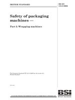
Figure A.1 illustrates the general concepts of risk reduction. The general model assumes that:
–
there is an EUC and a control system;
–
there are associated human factor issues;
–
the safety protective features comprise:
–
E/E/PE safety-related systems;
–
other risk reduction measures.
NOTE Figure A.1 is a generalised risk model to illustrate the general principles. The risk model for a specific
application will need to be developed taking into account the specific manner in which the necessary risk reduction
is actually being achieved by the E/E/PE safety-related systems and/or other risk reduction measures. The
resulting risk model may therefore differ from that shown in Figure A.1.
The various risks indicated in Figure A.1 and A.2 are as follows:
–
EUC risk: the risk existing for the specified hazardous events for the EUC, the EUC
control system and associated human factor issues: no designated safety protective
features are considered in the determination of this risk (see 3.1.9 of IEC 61508-4);
–
tolerable risk; the risk which is accepted in a given context based on the current values of
society (see 3.1.7 of IEC 61508-4);
–
residual risk: in the context of this standard, the residual risk is that remaining for the
specified hazardous events for the EUC, the EUC control system, human factor issues but
with the addition of, E/E/PE safety-related systems and other risk reduction measures (see
also 3.1.7 of IEC 61508-4).
The EUC risk is a function of the risk associated with the EUC itself but taking into account
the risk reduction brought about by the EUC control system. To prevent unreasonable claims
for the safety integrity of the EUC control system, this standard places constraints on the
claims that can be made (see 7.5.2.5 of IEC 61508-1).
The necessary risk reduction is achieved by a combination of all the safety protective
features. The necessary risk reduction to achieve the specified tolerable risk, from a starting
Licensed Copy: Science & Technology Facilities Council, 25/08/2010 10:15, Uncontrolled Copy, (c) BSI
BS EN 61508-5:2010
– 14 –
61508-5 © IEC:2010
point of the EUC risk, is shown in Figure A.1 (relevant for a safety function operating in low
demand mode of operation).
Figure A.1 – Risk reduction – general concepts (low demand mode of operation)
Figure A.2 – Risk and safety integrity concept
A.5.2
Safety integrity for high demand mode applications
The required safety integrity of the E/E/PE safety-related systems and other risk reduction
measures shall be of such a level to ensure that:
–
the average probability of failure on demand of the safety-related systems is sufficiently
low to prevent the hazardous event frequency exceeding that required to meet the
tolerable risk; and/or
–
the average probability of failure per hour of the safety-related system is sufficiently low to
prevent the hazardous event frequency exceeding that required to meet the tolerable risk.
Figure A.3 illustrates the general concepts of high demand applications. The general model
assumes that:
–
there is a EUC and a control system;
Licensed Copy: Science & Technology Facilities Council, 25/08/2010 10:15, Uncontrolled Copy, (c) BSI
BS EN 61508-5:2010
61508-5 © IEC:2010
– 15 –
–
there are associated human factor issues;
–
the safety protective features comprise:
–
E/E/PE safety-related system operating in high demand mode;
–
other risk reduction measures.
Various demands on the E/E/PE safety related systems can occur as follows:
–
general demands from the EUC;
–
demands arising from failures in the EUC control system;
–
demands arising from human failures.
If the total demand rate arising from all the demands on the system exceeds 1 per year then
the critical factor is the dangerous failure rate of the E/E/PE safety-related system. Residual
hazard frequency can never exceed the dangerous failure rate of the E/E/PE safety-related
system. It can be lower if other risk reduction measures reduce the probability of harm.
Figure A.3 – Risk diagram for high demand applications
A.5.3
Safety integrity for continuous mode applications
The required safety integrity of the E/E/PE safety-related systems and any other risk
reduction measures shall be of such a level to ensure that the average probability of a
dangerous failure per hour of the safety-related system is sufficiently low to prevent the
hazardous event frequency exceeding that required to meet the tolerable risk.
Licensed Copy: Science & Technology Facilities Council, 25/08/2010 10:15, Uncontrolled Copy, (c) BSI
BS EN 61508-5:2010
– 16 –
61508-5 © IEC:2010
With an E/E/PE safety-related system operating in continuous mode, other risk reduction
measures can reduce the residual hazard frequency according to the risk reduction provided
The model is shown in Figure A.4.
Figure A.4 – Risk diagram for continuous mode operation
A.5.4
Common cause and dependency failures
During the determination of the safety integrity levels it is important to take account of
common cause and dependency failures. The models shown above in Figures A.1, A.2, A.3
and A.4 are drawn on the basis that each safety system relevant to the same hazard is fully
independent. There are many applications where this is not the case. Examples include the
following:
1) Where a dangerous failure of an element within the EUC control system can cause a
demand on a safety-related system and the safety-related system uses an element subject
to failure from the same cause. An example of this could be where the control and
protection system sensors are separate but common cause could lead to failure of both
(see Figure A.5).
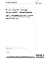
2) Where more than one safety-related system is used and some of the same type of
equipment is used within each safety-related system and each is subject to failure from
the same common cause. An example would be where the same type of sensor is used in
two separate protection systems both providing risk reduction for the same hazard (see
Figure A.6).
3) Where more than one protection system is used, the protection systems are diverse but
proof testing is carried out on all the systems on a synchronous basis. In such cases the
actual PFD avg achieved by the combination of multiple systems will be significantly higher
than the PFD avg suggested by the multiplication of the PFD avg of the individual systems.
4) Where the same individual element is used as part of the control system and the safetyrelated system.
5) Where more than one protection system is used and where the same individual element is
used as part of more than one system.
In such cases the effect of common cause/dependency will need to be considered.
Consideration should be given as to whether the final arrangement is capable of meeting the
necessary systematic capability and the necessary probability of dangerous random hardware
failure rates relating to the overall risk reduction required. The effect of common cause
failures is difficult to determine and often requires the construction of special purpose models
(e.g. fault tree or Markov models).
Licensed Copy: Science & Technology Facilities Council, 25/08/2010 10:15, Uncontrolled Copy, (c) BSI
BS EN 61508-5:2010
61508-5 © IEC:2010
– 17 –
The effect of common cause is likely to be more significant in applications involving high
safety integrity levels. In some applications it may be necessary to incorporate diversity so
that common cause effects are minimised. It should however be noted that incorporation of
diversity can lead to problems during design, maintenance and modification. Introducing
diversity can lead to errors due to the unfamiliarity and lack of operation experience with the
diverse devices.
Figure A.5 – Illustration of common cause failures (CCFs) of elements in the EUC
control system and elements in the E/E/PE safety-related system
Licensed Copy: Science & Technology Facilities Council, 25/08/2010 10:15, Uncontrolled Copy, (c) BSI
BS EN 61508-5:2010
– 18 –
61508-5 © IEC:2010
≤
Figure A.6 – Common cause between two E/E/PE safety-related systems
A.5.5
Safety Integrity levels when multiple layers of protection are used
When multiple layers of protection are used to achieve a tolerable risk there may be
interactions between systems themselves and also between systems and causes of demand.
As discussed above in A.5.4 there are always concerns about test (de)synchronisation and
common cause failures since these can be significant factors when overall risk reduction
requirements are high or where demand frequency is low. Evaluation of the interactions
between safety layers and between safety layers and causes of demand can be complex and
may need the development of a holistic model (e.g. as described in ISO/IEC 31010) and
based, for example on a top down approach with the top event specified as the tolerable
hazard frequency. The model may include all safety layers for calculating the actual risk
reduction and all causes of demand for calculating the actual frequency of accident. This
allows the identification of minimal cut sets (i.e. failure scenarios), reveals the weak points
(i.e. the shortest minimal cut sets: single, double failures, etc.) in the arrangement of systems
and facilitates system improvement through sensitivity analysis.
A.6
Risk and safety integrity
It is important that the distinction between risk and safety integrity be fully appreciated. Risk
is a measure of the probability and consequence of a specified hazardous event occurring.
This can be evaluated for different situations (EUC risk, risk reduction required to meet the
tolerable risk, actual risk (see Figure A.1). The tolerable risk is determined by consideration of
the issues described in A.2. Safety integrity applies solely to the E/E/PE safety-related
systems and other risk reduction measures and is a measure of the likelihood of those
systems/facilities satisfactorily achieving the necessary risk reduction in respect of the
specified safety functions. Once the tolerable risk has been set, and the necessary risk
reduction estimated, the safety integrity requirements for the safety-related systems can be
allocated (see 7.4, 7.5 and 7.6 of IEC 61508-1).
NOTE
The allocation is necessarily iterative in order to optimize the design to meet the various requirements.
Licensed Copy: Science & Technology Facilities Council, 25/08/2010 10:15, Uncontrolled Copy, (c) BSI
BS EN 61508-5:2010
61508-5 © IEC:2010
A.7
– 19 –
Safety integrity levels and software systematic capability
To cater for the wide range of necessary risk reductions that the safety-related systems have
to achieve, it is useful to have available a number of safety integrity levels as a means of
satisfying the safety integrity requirements of the safety functions allocated to the safetyrelated systems. Software systematic capability is used as the basis of specifying the safety
integrity requirements of the safety functions implemented in part by safety-related software.
The safety integrity requirements specification should specify the safety integrity levels for the
E/E/PE safety-related systems.
In this standard, four safety integrity levels are specified, with safety integrity level 4 being the
highest level and safety integrity level 1 being the lowest.
The safety integrity level target failure measures for the four safety integrity levels are
specified in Tables 2 and 3 of IEC 61508-1. Two parameters are specified, one for safetyrelated systems operating in a low demand mode of operation and one for safety-related
systems operating in a high demand or continuous mode of operation.
NOTE For safety-related systems operating in a low demand mode of operation, the safety integrity measure of
interest is the probability of failure to perform its design function on demand. For safety-related systems operating
in a high demand or continuous mode of operation, the safety integrity measure of interest is the average
probability of a dangerous failure per hour (see 3.5.16 and 3.5.17 of IEC 61508-4).
A.8
Allocation of safety requirements
The allocation of safety requirements (both the safety functions and the safety integrity
requirements) to the E/E/PE safety-related systems, other technology safety-related systems
and other risk reduction measures is shown in Figure A.7 (this is identical to Figure 6 of
IEC 61508-1). The requirements for the safety requirements allocation phase are given in 7.6
of IEC 61508-1.
The methods used to allocate the safety integrity requirements to the E/E/PE safety-related
systems, other technology safety-related systems and other risk reduction measures depend,
primarily, upon whether the necessary risk reduction is specified explicitly in a numerical
manner or in a qualitative manner. These approaches are termed quantitative and qualitative
methods respectively (see Annexes C, D, E, F and G).
Licensed Copy: Science & Technology Facilities Council, 25/08/2010 10:15, Uncontrolled Copy, (c) BSI
BS EN 61508-5:2010
– 20 –
61508-5 © IEC:2010
NOTE 1
Safety integrity requirements are associated with each safety function before allocation
(see 7.5.2.3 and 7.5.2.4 of IEC 61508-1).
NOTE 2
A safety function may be allocated across more than one safety-related system.
Figure A.7 – Allocation of safety requirements to the E/E/PE safety-related systems,
and other risk reduction measures
A.9
Mitigation systems
Mitigation systems take action in the event of full or partial failure of other safety-related
systems such as E/E/PE safety-systems. The objective is to reduce the consequences
associated with a hazardous event rather than its frequency. Examples of mitigation systems
include fire and gas systems (detection of fire/gas and subsequent action to put the fire out
(e.g. by water deluge), and airbag systems in an automobile.
When determining the safety integrity requirements it should be recognised that when making
judgments on the severity of the consequence, only the incremental consequences should be
considered. That is, determine the increase in the severity of the consequence if the function
did not operate over that when it does operate as intended. This can be done by first
considering the consequences if the system fails to operate and then considering what
difference will be made if the mitigation function operates correctly. In considering the
consequences if the system fails to operate there will normally be a number of outcomes all
with different probabilities. Event tree analysis (ETA) may be a useful tool for this.
NOTE Guidance on the determination of safety integrity levels for fire and gas and emergency shut down systems
is included in Annex B of ISO 10418.
Licensed Copy: Science & Technology Facilities Council, 25/08/2010 10:15, Uncontrolled Copy, (c) BSI
BS EN 61508-5:2010
61508-5 © IEC:2010
– 21 –
Annex B
(informative)
Selection of methods for determining
safety integrity level requirements
B.1
General
This annex lists a number of techniques that can be used for determination of safety integrity
levels. None of the methods are suitable for all applications and users will need to select the
most suitable. In selecting the most appropriate method consideration should be given to the
following factors:
1) the risk acceptance criteria that need to be met. Some of the techniques will not be
suitable if it is required to demonstrate that risk has been reduced to as low as reasonably
practicable;
2) the mode of operation of the safety function. Some methods are only suitable for low
demand mode;
3) the knowledge and experience of the persons undertaking the SIL determination and what
has been the traditional approach in the sector;
4) the confidence needed that the resulting residual risk meets the criteria specified by the
user organisation. Some of the methods can be linked back to quantified targets but some
approaches are qualitative only;
5) more than one method may be used. One method may be used for screening purposes
followed by another more rigorous approach if the screening method shows the need for
high safety integrity levels;
6) the severity of the consequences. More rigorous methods may be selected for consequences that include multiple fatalities;
7) whether common cause occurs between the E/E/PE safety related systems or between the
E/E/PE safety related system and demand causes.
Whatever method is used all assumptions should be recorded for future safety management.
All decisions should be recorded so that the SIL assessment can be verified and be subject to
independent functional safety assessment.
B.2
The ALARP method
The ALARP principles may be used on its own or with other methods to determine the SIL
requirements for a safety function. It can be used in a qualitative or quantitative way. When
used in a qualitative way the SIL requirements for a specified safety function are increased
until the frequency of occurance is reduced such that the conditions associated with Class II
or Class III risk class are satisfied. When used in a quantitative way frequencies and
consequences are specified numerically and the SIL requirements increased until it can be
shown that the additional capital and operating cost associated with implementing a higher
SIL would meet the condition associated with Class II or Class III risk class (see Figure C.1).
In using the ALARP method the boundary between the intolerable region and the ALARP
region will need to be considered.
B.3
Quantitative method of SIL determination
The quantitative method is described in Annex D. It may be used together with the ALARP
method described in Annex C.
Licensed Copy: Science & Technology Facilities Council, 25/08/2010 10:15, Uncontrolled Copy, (c) BSI
BS EN 61508-5:2010
– 22 –
61508-5 © IEC:2010
The quantitative method can be used for both simple and complex applications. With complex
applications, fault trees can be constructed to represent the hazard model. The top event will
generally be one or more fatalities and logic constructed to represent demand causes and
failures of the E/E/PE safety related systems that lead to the top event. Software tools are
available to allow modeling of common cause if the same type of equipment is used for
control and protection functions. In some complex applications, a single failure event may
occur in more than one place in the fault tree and this will require a boolean reduction to be
carried out. The tools also facilitate sensitivity analysis that shows the dominant factors that
influence the frequency of the top event. SIL can be established by determining the required
risk reduction to achieve the tolerable risk criteria.
The method is suitable for safety functions operating in continuous/high demand mode and
low demand mode. The method normally results in low SILs because the risk model is
specifically designed for each application and numeric values are used to represent each risk
factor rather than the numeric ranges used in calibrated risk graphs. Quantitative methods
however require the construction of a specific model for each hazardous event. Modeling
requires skill, tools and knowledge of the application and can take considerable time to
develop and verify.
The method facilitates demonstration that risk has been reduced to as low as reasonably
practicable. This can be done by considering options for further risk reduction, integrating the
additional facilities in the fault tree model and then determining the reduction in risk and
comparing this with the cost of the option.
B.4
The risk graph method
The risk graph qualitative method is described in Annex E. The method enables the safety
integrity level to be determined from knowledge of the risk factors associated with the EUC
and the EUC control system. A number of parameters are introduced which together describe
the nature of the hazardous situation when safety related systems fail or are not available.
One parameter is chosen from each of four sets, and the selected parameters are then
combined to decide the safety integrity level allocated to the safety functions. The method has
been used extensively within the machinery sector, see ISO 14121-2 and Annex A of ISO
13849-1.
The method can be qualitative in which case the selection of the parameters is subjective and
requires considerable judgment. The residual risk cannot be calculated from knowledge of the
parameter values. It will not be suitable if an organisation requires confidence that residual
risk is reduced to a specified quantitative value.
The parameters descriptions can include numeric values that are derived by calibrating the
risk graph against numeric tolerability risk criteria. The residual risk can be calculated from
numeric values used for each of the parameters. It will be suitable if an organisation requires
confidence that residual risk is reduced to a specified quantitative value. Experience has
shown that use of the calibrated risk graph method can result in high safety integrity levels.
This is because calibration is usually carried out using worst case values of each parameter.
Each parameter has a decade range so that for applications where all the parameters are
average for the range, the SIL will be one higher than necessary for tolerable risk. The
method is extensively used in the process and offshore sector.
The risk graph method does not take into account common cause failures between causes of
demand and cause of the E/E/PE safety related system failure or common cause issues with
other layers of protection.
Licensed Copy: Science & Technology Facilities Council, 25/08/2010 10:15, Uncontrolled Copy, (c) BSI
BS EN 61508-5:2010
61508-5 © IEC:2010
B.5
– 23 –
Layer of protection analysis (LOPA)
The basic method is described in a number of books and the technique can be used in a
number of different forms. A technique that can be used for SIL determination is described in
Annex F.
The method is quantitative and the user will need to decide the tolerable frequencies for each
consequence severity level. Numeric credit is given for protection layers that reduce the
frequency of individual demand causes. Not all protection layers are relevant to all demand
causes, so the technique can be used for more complex applications. The numeric values
assigned to protection layers can be rounded up to the next significant figure or the next
significant decade range. If numeric values of protection layers are rounded to the next
significant figure, then the method on average gives lower requirements for risk reduction and
lower SIL values than calibrated risk graphs.
Since numeric targets are assigned to specified consequence severity levels, the user can
have confidence that residual risk meets corporate criteria.
The method as described is not suitable for functions that operate in continuous mode and
does not take account of common cause failure between causes of demand and the E/E/PE
safety related systems. The method can however be adjusted so as to be suitable for such
cases.
B.6
Hazardous event severity matrix
The hazard event severity method is described in Annex G. An inherent assumption is that
when a protection layer is added that an order of magnitude risk reduction is achieved. A
further assumption is that protection layers are independent of demand cause and
independent of each other. The method as described is not suitable for functions that operate
in continuous mode. The method can be qualitative in which case the selection of the risk
factors is subjective and requires considerable judgment. The residual risk cannot be
calculated from knowledge of the risk factors selected. It will not be suitable if an organization
requires confidence that residual risk is reduced to a specified quantitative value.