Bsi bs en 12066 1998
Bạn đang xem bản rút gọn của tài liệu. Xem và tải ngay bản đầy đủ của tài liệu tại đây (214.37 KB, 12 trang )
BRITISH STANDARD
Installations and equipment
for liquefied natural gas Ð
Testing of insulating linings
for liquefied natural gas
impounding areas
The European Standard EN 12066 : 1997 has the status of a
British Standard
ICS 75.200
NO COPYING WITHOUT BSI PERMISSION EXCEPT AS PERMITTED BY COPYRIGHT LAW
|
|
|
|
|
|
|
|
|
|
|
|
|
|
|
|
|
|
|
|
|
|
|
|
|
|
|
|
|
|
|
|
|
|
|
|
|
|
|
|
|
|
|
|
|
|
|
|
|
|
|
|
|
|
|
|
|
|
|
|
|
|
|
|
|
|
|
|
|
|
|
|
|
|
|
|
|
|
|
|
|
|
|
|
|
|
|
|
|
|
|
|
|
|
|
|
|
|
|
|
|
|
|
|
|
|
|
|
|
|
|
|
|
|
|
|
|
|
|
|
|
|
|
|
|
|
|
|
|
BS EN
12066 : 1998
BS EN 12066 : 1998
National foreword
This British Standard is the English language version of EN 12066 : 1997.
The UK participation in its preparation was entrusted to Technical Committee
GSE/38, Installation and equipment for LNG, which has the responsibility to:
± aid enquirers to understand the text;
± present to the responsible European committee any enquiries on the
interpretation, or proposals for change, and keep the UK interests informed;
± monitor related international and European developments and promulgate
them in the UK.
A list of organizations represented on this committee can be obtained on request to
its secretary.
Cross-references
The British Standards which implement international or European publications
referred to in this document may be found in the BSI Standards Catalogue under the
section entitled `International Standards Correspondence Index', or by using the
`Find' facility of the BSI Standards Electronic Catalogue.
Compliance with a British Standard does not of itself confer immunity
from legal obligations.
Summary of pages
This document comprises a front cover, an inside front cover, the EN title page,
pages 2 to 8, an inside back cover and a back cover.
This British Standard, having
been prepared under the
direction of the Engineering
Sector Board, was published
under the authority of the
Standards Board and comes into
effect on 15 February 1998
BSI 1998
ISBN 0 580 28980 X
Amendments issued since publication
Amd. No.
Date
Text affected
EN 12066
EUROPEAN STANDARD
NORME EUROPÊENNE
EUROPẰISCHE NORM
September 1997
ICS 75.200
Descriptors: Gas installation, liquefied natural gas, vats, protective coatings, insulation, evaporation, water bath evaporation,
operating requirements, tests, test equipment, measurements, coefficients, computation
English version
Installations and equipment for liquefied natural gas Ð
Testing of insulating linings for liquefied natural gas
impounding areas
Installations et eÂquipements relatifs au gaz naturel
liqueÂfie РEssais de reveÃtements isolants des
cuvettes de reÂtention de gaz naturel liqueÂfieÂ
Anlagen und AusruÈstung fuÈr FluÈssigerdgas Ð
PruÈfung von WaÈrmedammbeschichtungen fuÈr
FluÈssigerdgas-Auffanbecken
This European Standard was approved by CEN on 22 August 1997.
CEN members are bound to comply with the CEN/CENELEC Internal Regulations
which stipulate the conditions for giving this European Standard the status of a
national standard without any alteration. Up-to-date lists and bibliographical
references concerning such national standards may be obtained on application to
the Central Secretariat or to any CEN member.
This European Standard exists in three official versions (English, French, German).
A version in any other language made by translation under the responsibility of a
CEN member into its own language and notified to the Central Secretariat has the
same status as the official versions.
CEN members are the national standards bodies of Austria, Belgium, Czech
Republic, Denmark, Finland, France, Germany, Greece, Iceland, Ireland, Italy,
Luxembourg, Netherlands, Norway, Portugal, Spain, Sweden, Switzerland and the
United Kingdom.
CEN
European Committee for Standardization
Comite EuropeÂen de Normalisation
EuropaÈisches Komitee fuÈr Normung
Central Secretariat: rue de Stassart 36, B-1050 Brussels
1997 CEN All rights of exploitation in any form and by any means reserved worldwide for CEN national
Members.
Ref. No. EN 12066 : 1997 E
Page 2
EN 12066 : 1997
Foreword
This European Standard has been prepared by
Technical Committee CEN/TC 282, Installation and
equipment for LNG, the secretariat of which is held by
AFNOR.
This European Standard shall be given the status of a
national standard, either by publication of an identical
text or by endorsement, at the latest by March 1998,
and conflicting national standards shall be withdrawn
at the latest by March 1998.
According to the CEN/CENELEC Internal Regulations,
the national standards organizations of the following
countries are bound to implement this European
Standard: Austria, Belgium, Czech Republic, Denmark,
Finland, France, Germany, Greece, Iceland, Ireland,
Italy, Luxembourg, Netherlands, Norway, Portugal,
Spain, Sweden, Switzerland and the United Kingdom.
Contents
Foreword
1
Scope
2
Normative references
3
Definitions
4
Description of the means of and the
equipment required for testing
4.1 Characteristics of test pieces
4.2 Equipment used to measure the
evaporation coefficient of LNG in
contact with the insulating lining
4.3 Equipment used to measure the water
absorption ratio of an insulating lining
5
Test method
5.1 Measurement of the evaporation
coefficient of LNG in contact with the
insulating lining
5.2 Measurement of the water absorption
ratio of the insulating lining
6
Testing
7
Test report
Annexes
A
(normative) Specification of the test
rig
B
(normative) Measuring equipment
used to determine the evaporation
coefficient of LNG in contact with the
insulating lining
C
(normative) Method of calculation of
the evaporation coefficient of LNG in
contact with the insulating lining
D
(normative) Method of calculation of
the water absorption ratio of
insulating lining
Page
2
3
3
3
3
3
3
3
3
3
4
4
4
5
6
6
7
BSI 1998
Page 3
EN 12066 : 1997
1 Scope
This European Standard specifies the tests to be
carried out in order to assess the suitability of
insulating linings used in LNG impounding areas.
2 Normative references
This European Standard incorporates by dated or
undated reference, provisions from other publications.
These normative references are cited at the
appropriate places in the text and the publications are
listed hereafter. For dated references, subsequent
amendments to or revisions of any of these
publications apply to this European Standard only
when incorporated in it by amendment or revision. For
undated references the latest edition of the publication
referred to applies.
EN 1160
prEN 12379
Installations and equipment for
liquefied natural gas Ð General
characteristics of liquefied natural gas
Testing concrete Ð Making and curing
specimens for strength tests
3 Definitions
For the purposes of this standard, the following
definitions apply:
3.1 liquefied natural gas (LNG)
See EN 1160.
3.2 insulating lining
Material or layers of materials designed to minimize
evaporation of an LNG pool.
3.3 water absorption ratio
Ratio between the volume of water absorbed and the
calculated volume of the insulating lining specimen
subjected to testing.
4 Description of the means of and the
equipment required for testing
4.1 Characteristics of test pieces
The dimensions of the test pieces shall be defined in
accordance with the dimensions of the test rig defined
in 4.2.1.
The thickness of the test piece shall be the same as
that of the insulating lining of the LNG impounding
area.
The manufacturing and installation technology of the
test piece shall be the same as that of the impounding
area insulating lining.
The test piece shall be stored in accordance with the
manufacturer's recommendations. Specifically, if the
material applied is concrete, the test pieces shall be
built, cured and stored in compliance with prEN 12379.
BSI 1998
4.2 Equipment used to measure the evaporation
coefficient of LNG in contact with the
insulating lining
4.2.1 Test rig
A test piece shall be hermetically sealed onto the base
of a right-angled parallelepiped shaped tank whose
sides and bottom are built of a rigid insulating material
having a thermal conductivity less than 0,050 W/(m´K).
The quantity of LNG necessary for the test shall be
discharged over the test piece in less than 0,5 s.
The discharged volume is equal to the product of the
test piece surface and the desired height of LNG within
a limit deviation of ± 5 %.
After the LNG discharge, the initial height of LNG over
the test piece shall be about 2,5 cm.
Annex A specifies the characteristics of the test rig.
NOTE. Given the different thermal behaviour of other cryogenic
lquids, none of them can replace LNG to measure the evaporation
coefficient.
4.2.2 Measuring equipment
The evaporation coefficient of LNG in contact with the
insulating lining shall be determined on the basis of
continuous weighings of the tank placed on a scale,
following LNG discharge over the test piece.
For that purpose, an electronic scale shall be used in
combination with a high-speed recorder.
Annex B specifies the characteristics of the measuring
equipment.
4.3 Equipment used to measure the water
absorption ratio of an insulating lining
4.3.1 Water tank
The water tank shall be designed in such a way that
the test piece is fully immersed and its six faces
remain in permanent contact with water during
immersion.
4.3.2 Measuring equipment
The water absorption ratio of the test pieces shall be
measured after successive weighings of test pieces on
previously calibrated scales. The weighing scale shall
be able to measure with an accuracy better than 1 %.
5 Test method
5.1 Measurement of the evaporation coefficient
of LNG in contact with the insulating lining
5.1.1 Procedure
The test for the measurement of the evaporation
coefficient of LNG in contact with the insulating lining
shall be performed at an initial test rig temperature of
(20 ± 5) ÊC and at atmospheric pressure in accordance
with the following procedure:
a) install the test piece at the base of the tank;
b) install the tank on the scale;
c) install the LNG discharge system above the tank;
Page 4
EN 12066 : 1997
d) fill the tip-over system;
e) discharge the LNG over the test piece within a
period of less than 0,5 s;
f) record the tank weight at high frequency for a
period of at least 2 min;
g) visually inspect the test rig to verify its tightness.
5.1.2 The parameter derived from the
measurements
The evaporation coefficient of LNG, Kr, in contact with
the insulating lining shall be calculated in accordance
with annex C, by quantifying the rate of evaporation of
LNG in contact with the insulating lining under test.
5.2 Measurement of the water absorption ratio
of the insulating lining
5.2.1 Procedure
The test for the measurement of the water absorption
ratio of the insulating lining shall be performed at a
temperature of (20 ± 5) ÊC in accordance with the
following procedure:
a) weigh a test piece before testing;
b) immerse in water for 1 h;
c) weigh after draining for 1 h;
d) immerse in water for one day;
e) weigh after draining for 1 h;
f) immerse in water for two days;
g) weigh after draining for 1 h;
h) repeat the last two sequences (f and g) six times.
5.2.2 Parameters derived from the measurements
The water absorption ratio of the insulating lining shall
be quantified by calculating the following parameters:
a) the water absorption ratio of each test piece after
each weighing;
b) the maximum value of water absorption ratio of
the insulating lining.
Annex D specifies the method of calculation of the
above parameters.
6 Testing
The tests shall be carried out on the three test pieces
in order to determine the evaporation coefficient of
LNG in contact with the insulating lining under the
following conditions:
a) the insulating lining is dry as delivered by the
manufacturer;
b) the insulating lining is saturated with water
following immersion for 15 days;
c) due to the fact that the insulating material can
change its characteristics under the influence of
atmospheric agents such as rain, frost, ultra-violet
rays etc, it is recommended to determine the
evaporation coefficient of LNG after having
subjected the insulating lining to an ageing
procedure. In this case, the ageing procedure shall
be defined by the user and agreed by the insulating
manufacturer. The simulated lifetime shall be defined
by the user.
7 Test report
The results of the tests shall be recorded in a report
containing the following information:
a) the history of the test pieces before testing, such
as storage and transportation conditions
(temperature, humidity, etc), time between
manufacturing and testing and conditions of
sampling;
b) the evaporation coefficient of LNG in contact
with the insulating lining in the dry condition
(see clause 6a));
c) the maximum value of the water absorption ratio
of the insulating lining (see 5.2.2b));
d) the evaporation coefficient of LNG in contact
with the insulating lining saturated with water
following immersion for 15 days (see clause 6b));
e) the evaporation coefficient of LNG in contact with
the insulating lining following the accelerated ageing
procedure, if requested (see clause 6c)).
BSI 1998
Page 5
EN 12066 : 1997
Annex A (normative)
Specification of the test rig
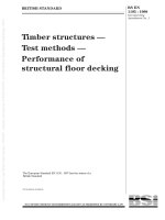
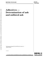
A.1 Description of the test rig
The test rig shall consist of the following
(see figure A.1):
± a tank containing the test piece;
± a system of LNG discharge.
The materials which are likely to come in contact with
LNG shall comply with the requirements of EN 1160.
A.3 Specification of the LNG discharge system
The LNG discharge system shall consist of:
± a quick tip-over system;
± a cover to prevent any LNG splashing;
± a hopper to guide the LNG discharge into the tank.
A.4 Regulations
Attention is drawn to existing European Standards in
the field of safety, for example prEN 50145, for the
design and operation of the test rig.
A.2 Specification of the tank
The tank shall be designed so that its base is a square
whose side is between 400 mm and 600 mm.
It shall consist of plates of a rigid insulating material
forming the sides and base.
The test piece shall be sealed onto the base.
In order to avoid LNG penetration along the edges of
the test piece and under the test piece, special care
shall be taken when making the joints between the
different tank components.
1 Test piece
4 Quick tip-over system
2 Rigid insulation material
5 Cover
3 Tightening device
6 Hopper
Figure A.1 Example of test rig
BSI 1998
Page 6
EN 12066 : 1997
Annex B (normative)
Measuring equipment used to determine
the evaporation coefficient of LNG in
contact with the insulating lining
B.1 Specification of the scale
The scale used to determine the evaporation
coefficient of LNG in contact with the insulating lining
shall have the following specification:
a) sensitivity: 5 3 1023 kg;
b) indicator precision: 5 3 1023 kg;
c) frequency of measurement: at least 20 Hz.
B.2 Specification of related recorder
The recorder connected to the scale may be of the
magnetic or digital tape recording type. Regardless of
the type, its data acquisition frequency shall be at
least 20 Hz.
Annex C (normative)
Method of calculation of the evaporation
coefficient of LNG in contact with the
insulating lining
C.1 Calculation of LNG mass remaining in the
tank as a function of time
The rate of evaporation Vr(t) expressed in metres per
second, as a function of the time (t) that the LNG is in
contact with the insulating lining is calculated with a
law of the following type:
K
(C.1)
Vr(t) = r
√t
where:
Kr is the evaporation coefficient of LNG in contact
with the insulating lining expressed in m/s¯.
where:
M0 and A are experimental coefficients determined
after applying the method of least
squares to the mass measurements of
LNG remaining in the tank as a function
of time.
C.2 Calculation of evaporation coefficient of
LNG in contact with insulating lining
The coefficient Ai determined for a test piece
referenced i, has the following expression:
Ai = Kg ´ rLNG ´ (Sep + Sw )
(C.5)
i
i
i
where:
(expressed in m/s¯) is the overall evaporation
coefficient of LNG in contact with materials
wetted during the discharge (sides and test
piece referenced i);
rLNG is the LNG density expressed in kg/m3;
i
Sep is the surface area of an LNG-wetted test piece
expressed in m2;
Sw is the surface area of the side walls initially
i
wetted by the LNG expressed in m2.
Kg
i
The surface area Sw is calculated as follows:
i
M0i ´ p
Sw =
i
rLNG ´ Sep
i
where:
M0
(C.6)
is the initial mass of LNG discharged over the
test piece referenced i expressed
in kg;
is the perimeter of the test piece expressed in
metres.
i
p
Coefficient Kg has the following expression:
i
Consequently, the variation in the mass of evaporated
dMe (t)
LNG,
, is expressed as a function of time by a
dt
law of the following type:
dMe(t) A
=
dt
√t
where:
(C.2)
Me(t) is the mass of evaporated LNG expressed
in kg;
A
is a dimensional constant determined
experimentally expressed in kg/s¯.
Consequently, the LNG mass M(t) remaining in the
tank is expressed as a function of time by the
following law:
(C.3)
M(t) = M0 2 Me(t)
M(t) = M02 2A √ t
Kg =
i
Sep
Swi
´ Kep +
´ Kw
i
Sep + Sw
Sep + Sw
i
where:
Kep
i
Kw
(C.7)
i
is the evaporation coefficient of LNG in
contact with the insulating lining of the test
piece referenced i expressed in m/s¯;
is the evaporation coefficient of LNG in
contact with the tank walls, determined in
C.3 expressed in m/s¯.
The evaporation coefficient of LNG in contact with the
insulating lining of the test piece referenced i, is
expressed as follows:
S
Ai
2 wi ´ Kw
(C.8)
Kep =
i
rLNG ´ Sep Sep
i
(C.4)
BSI 1998
Page 7
EN 12066 : 1997
The evaporation coefficient of LNG in contact with the
insulating lining Kr is the mean value of the
coefficients calculated for each of the three test pieces:
Kr =
3
1
3
∑
Kep
(C.9)
i
i= 1
C.3 Calculation of evaporation coefficient of
LNG in contact with tank walls
The evaporation coefficient of LNG in contact with the
test piece referenced i of the same material as the tank
walls is expressed as follows:
Ai
(C.10)
Kw =
i
rLNG ´ Sep + Sw
i
(
i
)
The evaporation coefficient of LNG in contact with the
material of the tank walls KW is the mean value of the
coefficients calculated as follows:
Kw =
1
3
3
∑
i=1
Kw
(C.11)
i
C.4 Example of calculation
The tests described below were performed with three
square test pieces having the following dimensions:
± side: 400 mm;
± thickness: 70 mm;
± surface area: 0,16 m2.
The weight of the LNG discharged over the test piece
was measured by means of an electronic scale taking
readings every 50 ms for 2 min.
The tank walls were made of polyurethane. Hence, the
Kw coefficient has a value equal to 0,83 3 1024 m/s¯.
Table C.1 indicates, for each test piece referenced i, the
values of the following coefficients and physical
parameters:
± the dimensional constant Ai, determined according
to a law of the following type, after applying the
method of least squares to the measurements of the
LNG mass remaining over the test piece in the tank
as a function of time:
The evaporation coefficient of LNG in contact with the
insulating lining Kr is:
17,33 + 17,93 + 19,19
3 1025 m/s¯
Kr =
3
Kr = 18,15 3 1025 m/s¯
C.5 Bibliography
Emission and dispersion. Chapter 15 In: Frank P. Lees,
ed., Loss prevention in the process industries.
Liquids spills on the ground Ð Spreading and
evaporation. Chapter 6 In: Torstein K. FanneloÈp, ed.,
Fluid mechanics for industrial safety and
environmental protection.
MCNAUGHTON, D.J., and C.M. BERKOWITZ. Heavy
gas and risk assessment. In: Hartwig, ed., Overview of
U.S. research activities in the dispersion of dense
gases.
SHAW P., and F. BRISCOE. Evaporation from spills of
hazardous liquids on land and water. SRD, ed.
Annex D (normative)
Method of calculation of the water
absorption ratio of insulating lining
D.1 Water absorption ratio of a test piece after
immersion
The water absorption ratio, Prt, after an immersion
time, t, of a test piece is given by the following
formula:
m 2 m0
(D.1)
Pr = t
t
m0
where:
mt
m0
is the mass of the test piece after immersion
time t and after 1 h of dripping, on a flat
surface;
is the mass of the test piece before the first
immersion.
(C.12)
M(t) = M0 2 2Ai √ t
± the LNG density, rLNG ;
i
± the surface area Sw of the tank walls initially
wetted by the LNG; i
± the evaporation coefficient of LNG in contact with
the insulating lining, Kep .
i
Table C.1 Values of coefficients and physical parameters required for the calculation of the
evaporation coefficient of LNG
Reference of the test piece
1
2
3
Ai in kg/s¯
rLNGi in kg/m3
0,0131
453,7
0,0136
453,7
0,0145
453,7
Swi in m2
0,0137
0,0153
0,0149
Kepi in m/s¯
17,33 3 1025
17,93 3 1025
19,19 3 1025
BSI 1998
Page 8
EN 12066 : 1997
D.2 Maximum value of the water absorption
ratio of the insulating lining
The value of water absorption ratio of each test piece
determined experimentally as a function of immersion
time shall be adjusted by the least squares method by
using a law of the following type:
a t2 + bit
(D.2)
Pr (t) = 2 i
i
t + cit + di
where:
Pr (t)
is the water absorption ratio function of
the test piece referenced i;
ai, bi, ci, di are the adjustment coefficients of the
function Pr (t).
D.3 Numerical example
The table D.1 defines for each test piece:
± the weight, m0, before the first immersion;
± the weights mt after each immersion and the
corresponding values of the water absorption
ratio Pr ;
t
± the values of the adjustment coefficients ai, bi,
ci, di;
± the maximum values of the water absorption
ratio Pr .
maxi
i
i
The maximum value of the water absorption ratio for
the test piece referenced i is:
2
lim ait + bit
=
(D.3)
Pr
max
t ` t2 + c t + di
i
Pr
maxi
The maximum value of the water absorption ratio is:
10,61 + 10,28 + 9,55
%
Pr =
max
3
Pr = 10,15 %
max
i
= ai
(D.4)
The maximum value of the water absorption ratio for
the insulating lining is the following:
Pr
max
=
1
3
3
∑
Pr
i=1
(D.5)
maxi
Table D.1 Values of the numeric example
Reference of the test piece
1
2
m0 in kg
36
Immersion duration
mt
Pr
kg
%
37,53
38,02
38,67
38,97
39,15
39,27
39,35
39,41
39,46
10,61
221,01
60,90
27,36
10,61
4,25
5,62
7,42
8,26
8,75
9,08
9,30
9,47
9,60
1h
1 day
3 days
5 days
7 days
9 days
11 days
13 days
15 days
ai
bi
ci
di
Prmax
i
3
36
t
36
mt
Pr
kg
%
37,33
37,99
38,61
38,90
39,07
39,18
39,25
39,31
39,36
10,28
220,58
60,62
1,09
10,28
3,68
5,52
7,24
8,05
8,52
8,82
9,04
9,20
9,32
t
mt
Pr
kg
%
37,17
37,72
38,30
38,59
38,76
38,87
38,95
39,02
39,06
9,55
218,89
69,87
20,62
9,55
3,25
4,77
6,39
7,19
7,67
7,98
8,21
8,38
8,51
t
BSI 1998
blank
BSI
389 Chiswick High Road
London
W4 4AL
|
|
|
|
|
|
|
|
|
|
|
|
|
|
|
|
|
|
|
|
|
|
|
|
|
|
|
|
|
|
|
|
|
|
|
|
|
|
|
|
|
|
|
|
|
|
|
|
|
|
|
|
|
|
|
|
|
|
|
|
|
|
|
|
|
|
|
|
|
|
|
|
|
|
|
|
|
|
|
|
|
|
|
|
|
|
|
|
|
|
|
|
|
|
|
|
|
|
|
|
|
|
|
|
|
|
|
|
|
|
|
|
|
|
|
|
|
|
|
|
|
|
|
|
|
|
|
BSI Ð British Standards Institution
BSI is the independent national body responsible for preparing British Standards. It
presents the UK view on standards in Europe and at the international level. It is
incorporated by Royal Charter.
Revisions
British Standards are updated by amendment or revision. Users of British Standards
should make sure that they possess the latest amendments or editions.
It is the constant aim of BSI to improve the quality of our products and services. We
would be grateful if anyone finding an inaccuracy or ambiguity while using this
British Standard would inform the Secretary of the technical committee responsible,
the identity of which can be found on the inside front cover. Tel: 020 8996 9000.
Fax: 020 8996 7400.
BSI offers members an individual updating service called PLUS which ensures that
subscribers automatically receive the latest editions of standards.
Buying standards
Orders for all BSI, international and foreign standards publications should be
addressed to Customer Services. Tel: 020 8996 9001. Fax: 020 8996 7001.
In response to orders for international standards, it is BSI policy to supply the BSI
implementation of those that have been published as British Standards, unless
otherwise requested.
Information on standards
BSI provides a wide range of information on national, European and international
standards through its Library and its Technical Help to Exporters Service. Various
BSI electronic information services are also available which give details on all its
products and services. Contact the Information Centre. Tel: 020 8996 7111.
Fax: 020 8996 7048.
Subscribing members of BSI are kept up to date with standards developments and
receive substantial discounts on the purchase price of standards. For details of
these and other benefits contact Membership Administration. Tel: 020 8996 7002.
Fax: 020 8996 7001.
Copyright
Copyright subsists in all BSI publications. BSI also holds the copyright, in the UK, of
the publications of the international standardization bodies. Except as permitted
under the Copyright, Designs and Patents Act 1988 no extract may be reproduced,
stored in a retrieval system or transmitted in any form or by any means ± electronic,
photocopying, recording or otherwise ± without prior written permission from BSI.
This does not preclude the free use, in the course of implementing the standard, of
necessary details such as symbols, and size, type or grade designations. If these
details are to be used for any other purpose than implementation then the prior
written permission of BSI must be obtained.
If permission is granted, the terms may include royalty payments or a licensing
agreement. Details and advice can be obtained from the Copyright Manager.
Tel: 020 8996 7070.