Bsi bs en 01218 5 2004 + a1 2009
Bạn đang xem bản rút gọn của tài liệu. Xem và tải ngay bản đầy đủ của tài liệu tại đây (1.4 MB, 60 trang )
BS EN
1218-5:2004
BRITISH STANDARD
+A1:2009
Incorporating
corrigendum
Safety of woodworking
machines — Tenoning
machines —
Part 5: One side profiling machines with
fixed table and feed rollers or fed by
chain
ICS 79. 1 20. 1 0
?? ? ?????? ??????? ??? ?? ???????? ? ?? ? ?? ?? ?? ?????? ? ?? ? ???????? ???
?
?
?
?
?
?
?
?
?
?
December 2006
BS EN 1218-5:2004+A1:2009
National foreword
This British Standard is the UK implementation of
EN 1218-5:2004+A1:2009, incorporating corrigendum December 2006. It
supersedes BS EN 1218-5:2004 which is withdrawn.
The start and finish of text introduced or altered by amendment is
indicated in the text by tags. Tags indicating changes to CEN text
carry the number of the CEN amendment. For example, text altered by
CEN amendment A1 is indicated by
.
The UK participation in its preparation was entrusted to Technical
Committee MTE/23, Woodworking machines.
A list of organizations represented on this committee can be obtained on
request to its secretary.
This publication does not purport to include all the necessary provisions of a
contract. Users are responsible for its correct application.
!"
Compliance with a British Standard cannot confer immunity from
legal obligations.
Amendments/corrigenda issued since publication
This British Standard, was
published under the authority
of the Standards Policy and
Strategy Committee
on 22 July 2004
© BSI 2009
ISBN 978 0 580 68557 6
Amd. No.
Date
Comments
17020
30 April 2007
Addition to the key to Figure A.3, and
replacement of Annex ZA
Corrigendum No. 1
30 November 2009 Implementation of CEN amendment
A1:2009
EUROPEAN STANDARD
NORME EUROPÉENNE
EUROPÄISCHE NORM
EN 1218-5:2004+A1
September 2009
ICS 79.1 20.1 0
Supersedes EN 1 21 8-5:2004
English Version
Safety of woodworking machines - Tenoning machines - Part 5:
One side profiling machines with fixed table and feed rollers or
feed chain
Sécurité des machines pour le travail du bois Tenonneuses - Partie 5: Machines à profiler sur une face à
table fixe et avance par rouleaux ou par chne
Sicherheit von Holzbearbeitungsmaschinen Zapfenschneid- und Schlitzmaschinen - Teil 5: Einseitige
Profiliermaschinen mit festem Tisch und mit Vorschubrollen
oder mit Kettenbandvorschub
This European Standard was approved by CEN on 24 March 2004 and includes Corrigendum 1 issued by CEN on 20 December 2006 and
Amendment 1 approved by CEN on 30 July 2009.
CEN members are bound to comply with the CEN/CENELEC Internal Regulations which stipulate the conditions for giving this European
Standard the status of a national standard without any alteration. Up-to-date lists and bibliographical references concerning such national
standards may be obtained on application to the CEN Management Centre or to any CEN member.
This European Standard exists in three official versions (English, French, German). A version in any other language made by translation
under the responsibility of a CEN member into its own language and notified to the CEN Management Centre has the same status as the
official versions.
CEN members are the national standards bodies of Austria, Belgium, Bulgaria, Cyprus, Czech Republic, Denmark, Estonia, Finland,
France, Germany, Greece, Hungary, Iceland, Ireland, Italy, Latvia, Lithuania, Luxembourg, Malta, Netherlands, Norway, Poland, Portugal,
Romania, Slovakia, Slovenia, Spain, Sweden, Switzerland and United Kingdom.
EUROPEAN COMMITTEE FOR STANDARDIZATION
C O MITÉ EURO P ÉEN D E NO RMALIS ATIO N
E U RO P Ä I S C H E S KO M I T E E F Ü R N O RM U N G
Management Centre: Avenue Marnix 1 7, B-1 000 Brussels
© 2009 CEN
All rights of exploitation in any form and by any means reserved
worldwide for CEN national Members.
Ref. No. EN 1 21 8-5:2004+A1 :2009: E
BS EN 1 21 8-5:2004+A1 :2009
EN 1 21 8-5:2004+A1 :2009 (E)
Contents
page
Foreword .............................................................................................................................................................. 4
Introduction ......................................................................................................................................................... 5
1
Scope ...................................................................................................................................................... 6
2
Normative references ............................................................................................................................ 6
3
Terms and definitions ........................................................................................................................... 9
3.1
General .................................................................................................................................................... 9
3.2
Terms ...................................................................................................................................................... 9
3.3
Definitions ............................................................................................................................................ 1 1
4
List of significant hazards .................................................................................................................. 1 5
5
Safety requirements and/or measures .............................................................................................. 1 7
5.1
General .................................................................................................................................................. 1 7
5.2
Controls ................................................................................................................................................ 1 8
5.2.1 Safety and reliability of control systems ........................................................................................... 1 8
5.2.2 Position of controls ............................................................................................................................. 1 9
5.2.3 Starting ................................................................................................................................................. 1 9
5.2.4 Normal stopping .................................................................................................................................. 20
5.2.5 Emergency stop ................................................................................................................................... 20
5.2.6 Integrated feed ..................................................................................................................................... 20
5.2.7 Positioning of tool spindles ................................................................................................................ 21
5.2.8 Speed changing ................................................................................................................................... 21
5.2.9 Failure of the power supply ................................................................................................................ 21
5.2.1 0 Failure of control circuits .................................................................................................................... 21
5.3
Protection against mechanical hazards ............................................................................................ 22
5.3.1 Stability ................................................................................................................................................. 22
5.3.2
Risk of break-up during operation .......................................................................................... 22
5.3.3 Tool holder and tool design ................................................................................................................ 22
5.3.4 Braking .................................................................................................................................................. 24
5.3.5 Devices to minimise the possibility or the effect of ejection .......................................................... 26
5.3.6 Work-piece supports and guides ....................................................................................................... 30
5.3.7 Prevention of access to moving parts ............................................................................................... 31
5.4
Protection against non-mechanical hazards .................................................................................... 36
5.4.1 Fire ........................................................................................................................................................ 36
5.4.2 Noise ..................................................................................................................................................... 36
5.4.3 Emission of chips and dust ................................................................................................................ 37
5.4.4 Electricity .............................................................................................................................................. 37
5.4.5 Ergonomics and handling ................................................................................................................... 38
5.4.6 Lighting ................................................................................................................................................. 38
5.4.7 Pneumatics ........................................................................................................................................... 38
5.4.8 Hydraulics ............................................................................................................................................. 38
5.4.9
Electromagnetic compatibility ................................................................................................. 39
5.4.1 0 Static electricity ................................................................................................................................... 39
5.4.1 1 Errors of fitting ..................................................................................................................................... 39
5.4.1 2 Isolation ................................................................................................................................................ 39
5.4.1 3 Maintenance ......................................................................................................................................... 39
6
Information for use .............................................................................................................................. 40
6.1
Warning devices .................................................................................................................................. 40
6.2
Marking ................................................................................................................................................. 40
?
?
?
?
?
?
?
?
?
?
?
?
?
?
?
?
?
?
?
?
?
?
?
?
?
?
?
?
?
?
?
?
?
?
?
?
?
?
?
?
?
?
!
?
?
?
"
?
?
?
?
?
?
?
?
?
?
?
?
?
?
?
?
?
?
?
?
?
?
?
?
?
?
!
?
?
?
?
?
?
?
?
?
?
"
?
?
?
?
?
?
?
?
?
2
?
?
BS EN 1 21 8-5:2004+A1 :2009
EN 1 21 8-5:2004+A1 :2009 (E)
Instruction handbook .......................................................................................................................... 41
6.3
Annex A (informative) Examples of safety related electronic control systems...................................... 44
Annex B (normative) Tool spindle dimensional tolerances ....................................................................... 48
Annex C (normative) Operating conditions for noise emission measurement ...................................... 49
C.1
General ................................................................................................................................................. 49
C.2
Noise measurements .......................................................................................................................... 49
C.2.1 Test conditions .................................................................................................................................... 49
C.2.2 Microphone positions ......................................................................................................................... 49
C.2.3 General data sheet .............................................................................................................................. 51
Annex ZA (informative)
Relationship between this European Standard and the Essential
Requirements of EU Directive 98/37/EC ...................................................................................... 55
Annex ZB (informative)
Relationship between this European Standard and the Essential
Requirements of EU Directive 2006/42/EC .................................................................................. 56
Bibliography ...................................................................................................................................................... 57
?
?
?
?
?
?
?
?
?
?
?
?
?
?
!
!
?
"
"
?
?
?
3
BS EN 1 21 8-5:2004+A1 :2009
EN 1 21 8-5:2004+A1 :2009 (E)
Foreword
This document (EN 1 21 8-5:2004+A1 :2009) has been prepared by the Technical Committee CEN/TC 1 42
"Woodworking machines - Safety", the secretariat of which is held by UNI.
This European Standard shall be given the status of a national standard, either by publication of an identical
text or by endorsement, at the latest by March 20 1 0 , and conflicting national standards shall be withdrawn at
the latest by March 20 1 0 .
Attention is drawn to the possibility that some of the elements of this document may be the subject of patent
rights. CEN [and/or CENELEC] shall not be held responsible for identifying any or all such patent rights.
This document includes Amendment 1 , approved by CEN on 2009-07-30 and Corrigendum 1 , issued by CEN
on 2006-1 2-20.
This document supersedes EN 1 21 8-5:2004.
The start and finish of text introduced or altered by amendment is indicated in the text by tags
˜™
?
!"
?
?
?
The modifications of the related CEN Corrigendum have been implemented at the appropriate places in the
text and are indicated by the tags
?
?
?
!
"
This document has been prepared under a mandate given to CEN by the European Commission and the
European Free Trade Association, and supports essential requirements of
Machinery Directives .
! "
! EN 1 21 8 Safety of woodworking machines — Tenoning machines consists of the following parts:
For relationship with EU Directive(s), see informative Annexes ZA and ZB, which are integral parts of this
document.
Part 1: Single end tenoning machines with sliding table
Part 2: Double end tenoning and/or profiling machines fed by chain or chains
Part 3: Hand fed tenoning machines with sliding table for cutting structural timbers
Part 4: Edge banding machines fed by chain(s)
Part 5: One side profiling machines with fixed table and feed rollers or feed chain
"
Organisations contributing to the preparation of this European Standard include European Committee of
Woodworking Machinery Manufacturers Association "EUMABOIS".
The European Standards produced by CEN/TC 1 42 are particular to woodworking machines and complement
the relevant A and B Standards on the subject of general safety (see introduction of EN ISO 1 21 00-1 :2003 for
a description of A, B and C standards).
According to the CEN/CENELEC Internal Regulations, the national standards organizations of the following
countries are bound to implement this European Standard: Austria, Belgium, Bulgaria, Cyprus, Czech
Republic, Denmark, Estonia, Finland, France, Germany, Greece, Hungary, Iceland, Ireland, Italy, Latvia,
Lithuania, Luxembourg, Malta, Netherlands, Norway, Poland, Portugal, Romania, Slovakia, Slovenia, Spain,
Sweden, Switzerland and United Kingdom.
4
BS EN 1 21 8-5:2004+A1 :2009
EN 1 21 8-5:2004+A1 :2009 (E)
Introduction
This document has been prepared to be a harmonised standard to provide one means of conforming to the
essential safety requirements of the Machinery Directive, and associated EFTA regulations.
This document is a type C standard as stated in
! EN ISO 1 21 00-1 :2003" .
The machinery concerned and the extent to which hazards, hazardous situations and events covered are
indicated in the scope of this document.
When provisions of this type C standard are different from those which are stated in type A or B standards, the
provisions of this C type standard take precedence over the provisions of other standards, for machines that
have been designed and built in accordance with the provisions of this type C standard.
The requirements of this document are directed to manufacturers and their authorised representatives of one
side profiling machines with fixed table and feed rollers or feed chain. It is also useful for designers.
This document also includes information which can be provided by the manufacturer to the user.
Common requirements for tooling are given in
! EN 847-1 :2005" .
5
BS EN 1 21 8-5:2004+A1 :2009
EN 1 21 8-5:2004+A1 :2009 (E)
1
!
Scope
This document specifies all significant hazards, hazardous situations and events as listed in Clause 4
which are relevant to one side profiling machines with fixed table and feed rollers or feed chain hereinafter
referred to as "machines", where the loading and unloading is manual and where the maximum work-piece
height capacity is 200 mm. The machine is designed to process in one pass one side of solid wood, chip
board, fibreboard or plywood and also these materials where they are covered with plastic laminate. The
work-piece is fed through the processing units by an integrated feed consisting of rollers or a chain.
! deleted text"
"
This document does not apply to transportable machines.
This document does not deal with any hazards relating to:
a)
mechanical loading and/ or unloading of the work-piece; or
b)
a machine being used in combination with any other machine (as part of a line); or
c)
use of laser.
For Computer Numerically Controlled (CNC) machines this document does not cover hazards related to
Electro-Magnetic Compatibility (EMC).
NOTE 1 The requirements of this document apply to all machines whatever their method of control e.g.
electromechanical and/or electronic.
This document is primarily directed to machines which are manufactured after the date of publication by CEN.
NOTE 2 Single end tenoning machines with sliding table are dealt with in EN 1 21 8-1 :1 999. Double end tenoning and/or
profiling machines fed by chain or chains are dealt with in EN 1 21 8-2. Single end tenoning machines where the tenon is
produced only by means of saw-blades are dealt with in EN 1 21 8-3.
2 Normative references
The following referenced documents are indispensable for the application of this document. For dated
references, only the edition cited applies. For undated references, the latest edition of the referenced
document (including any amendments) applies.
! deleted text"
!principles
EN 61 4-1 :2006, Safety of machinery — Ergonomic design principles — Part 1: Terminology and general
"
! EN 847-1 :2005", Tools for woodworking — Safety requirements — Part 1: Milling tools and circular
sawblades
! EN 894-1 :1 997, Safety of machinery — Ergonomics requirements for the design of displays and control
actuators — Part 1: General principles for human interactions with displays and control actuators
EN 894-2:1 997, Safety of machinery — Ergonomics requirements for the design of displays and control
actuators — Part 2: Displays
6
BS EN 1 21 8-5:2004+A1 :2009
EN 1 21 8-5:2004+A1 :2009 (E)
EN 894-3:2000, Safety of machinery — Ergonomics requirements for the design of displays and control
actuators — Part 3: Control actuators
! deleted text"
"
EN 982:1 996, Safety of machinery — Safety requirements for fluid power systems and their components —
Hydraulics
EN 983:1 996, Safety of machinery — Safety requirements for fluid power systems and their components —
Pneumatics
! EN 1 005-1 :2001 , Safety of machinery — Human physical performance — Part 1: Terms and definitions
EN 1 005-2:2003, Safety of machinery — Human physical performance — Part 2: Manual handling of
machinery and component parts of machinery
EN 1 005-3:2002, Safety of machinery — Human physical performance — Part 3: Recommended force limits
for machinery operation
EN 1 005-4:2005, Safety of machinery — Human physical performance — Part 4: Evaluation of working
postures and movements in relation to machinery
"
EN 1 037:1 995, Safety of machinery — Prevention of unexpected start-up
! deleted text"
EN 1 088:1 995, Safety of machinery — Interlocking devices associated with guards — Principles for design
and selection
EN 1 760-2:2001 , Safety of machinery — Pressure sensitive protection devices — Part 2: General principles
for the design and testing of pressure sensitive edges and pressure sensitive bars
EN 1 837:1 999, Safety of machinery — Integral lighting of machines
! EN 50370-1 :2005, Electromagnetic compatibility (EMC) — Product family standard for machine-tools —
Part 1: Emission
EN 50370-2:2003, Electromagnetic compatibility (EMC) — Product family standard for machine-tools —
"
!requirements
EN 60204-1 :2006 " , Safety of machinery — Electrical equipment of machines — Part 1: General
! (IEC 60204-1:2005, modified) "
! EN 60439-1 :1 999, Low-voltage switchgear and controlgear assemblies — Part 1: Type-tested and partially
type-tested assemblies (IEC 60439-1:1999) "
Part 2: Immunity
EN 60529:1 991 , Degrees of protection provided by enclosures (IP Code) (IEC 60529:1989)
!
"
!
"
!switching
EN 60947-5-1 :2004 " , Low-voltage switchgear and control gear — Part 5-1: Control circuit devices and
elements — Electromechanical control circuit devices ! (IEC 60947-5-1:2003) "
! EN 61 31 0-1 :2008, Safety of machinery — Indication, marking and actuation — Part 1: Requirements for
visual, auditory and tactile signals (IEC 61310-1:2007) "
EN 60947-4-1 :2001 , Low-voltage switchgear and control gear — Part 4-1: Contactors and motorstarters — Electromechanical contactors and motor starters (IEC 60947-4-1:2000)
EN ISO 354:2003, Acoustics — Measurement of sound absorption in a reverberation room (ISO 354:2003)
7
BS EN 1 21 8-5:2004+A1 :2009
EN 1 21 8-5:2004+A1 :2009 (E)
EN ISO 3743-1 :1 995, Acoustics — Determination of sound power levels of noise sources — Engineering
methods for small, moveable sources in reverberant fields — Part 1: Comparison method for hard walled test
rooms (ISO 3743-1:1994)
EN ISO 3743-2:1 996, Acoustics — Determination of sound power levels of noise sources using sound
pressure — Engineering methods for small, moveable sources in reverberant fields — Part 2: Methods for
special reverberation test rooms (ISO 3743-2:1994)
EN ISO 3744:1 995, Acoustics — Declaration of sound power levels of noise sources using sound pressure —
Engineering method in an essentially free field over a reflecting plane (ISO 3744:1994)
EN ISO 3745:2003, Acoustics — Determination of sound power levels of noise sources — Precision methods
for anechoic and semi-anechoic rooms (ISO 3745:2003)
EN ISO 3746:1 995, Acoustics — Determination of sound power levels of noise sources using sound pressure
— Survey method using an enveloping measurement surface over a reflecting plane (ISO 3746:1995)
EN ISO 4871 :1 996, Acoustics — Determination and verification of noise emission values of machinery and
equipment (ISO 4871:1996)
EN ISO 961 4-1 :1 995, Acoustics — Determination of sound power levels of noise sources using sound
intensity — Part 1: Measurement at discrete points (ISO 9614-1:1993)
EN ISO 1 1 202:1 995, Acoustics — Noise emitted by machinery and equipment — Measurement of emission
sound pressure levels at a workstation and at other specified positions (ISO 11202:1995)
EN ISO 1 1 204:1 995, Acoustics — Noise emitted by machinery and equipment — Measurement of emission
sound pressure levels at a workstation and at other specified positions — Method requiring environmental
corrections (ISO 11204:1995)
EN ISO 1 1 688-1 :1 998, Acoustics — Recommended practice for the design of low noise machinery and
equipment — Part 1: Planning (ISO/TR 11688-1:1995)
EN ISO 1 21 00-1 :2003, Safety of machinery — Basic concepts, general principles for design — Part 1: Basic
terminology, methodology (ISO 12100-1:2003)
EN ISO 1 21 00-2:2003, Safety of machinery — Basic concepts, general principles for design — Part 2:
Technical principles (ISO 12100-2:2003)
!
!(ISOEN13850:2006)
ISO 1 3850:2008,
"
EN ISO 1 3849-1 :2008, Safety of machinery — Safety-related parts of control systems — Part 1: General
principles for design (ISO 13849-1:2006)
"
Safety of machinery — Emergency stop — Principles for design
ISO 286-2:1 988, ISO system of limits and fits — Part 2: Tables of standard tolerance grades and limit
deviations for holes and shafts
!insulation
HD 21 .1 S4:2002, Cables of rated voltages up to and including 450/750 V and having thermoplastic
— Part 1: General requirements"
!insulation
HD 22.1 S4:2002, Cables of rated voltages up to and including 450/750 V and having cross-linked
— Part 1: General requirements"
8
BS EN 1 21 8-5:2004+A1 :2009
EN 1 21 8-5:2004+A1 :2009 (E)
3 Terms and definitions
3.1 General
!
For the purposes of this document, the terms and definitions given in
EN ISO 1 21 00-1 :2003
Additional definitions specifically needed for this document are shown in 3.2 and 3.3
" apply.
3.2 Terms
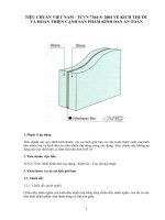
The main parts of a one side profiling machine with fixed table and feed rollers or feed chain and their
terminology are illustrated in Figures 1 and 2.
9
BS EN 1 21 8-5:2004+A1 :2009
EN 1 21 8-5:2004+A1 :2009 (E)
6
11
10
5
5
4
3
2
1
8
Key
1
2
3
4
5
6
7
8
9
10
11
9
8
9
Feed direction
Trip device at in feed of the machine
Controls
Feed rollers
Milling tools
Integral enclosure
Fixed table
Deterring/impeding device above the work-piece
Deterring/impeding device below the work-piece
Glass bead saw unit (optional)
Hinge recessing unit (optional)
Figure 1 — Terminology of a machine with roller feed
10
7
BS EN 1 21 8-5:2004+A1 :2009
EN 1 21 8-5:2004+A1 :2009 (E)
4
12
11
5
5
6
3
2
1
9
Key
1
2
3
4
5
6
7
8
9
10
11
12
10
9
10
8
7
Feed direction
Trip device at in feed of the machine
Controls
Pressure belt
Milling tools
Integral enclosure
Fixed table
Feed chain
Deterring/impeding device above the work-piece
Deterring/impeding device below the work-piece
Glass bead saw unit (optional)
Hinge recessing unit (optional)
Figure 2 — Terminology of a machine with chain feed
3.3 Definitions
3.3.1
one side profiling machine with fixed table and feed rollers or feed chain
machine designed to profile one side of the work-piece in one pass (see for an example of one side profiling
machine Figure 3). The machine consists of a zone for milling with one or more vertical tool spindles. In
addition the cutting and recovery of a glass bead (glass bead saw unit – see Figure 4) and/or hinge recessing
(hinge recessing unit – see Figure 5) may be provided
11
BS EN 1 21 8-5:2004+A1 :2009
EN 1 21 8-5:2004+A1 :2009 (E)
Figure 3 — Example of a one side profiling machine
3.3.2
integrated feed of one side profiling machines with fixed table and feed rollers or feed chain
feed mechanism for the work-piece which is integrated with the machine and where the work-piece is
held/controlled mechanically during the machining operation. The feed mechanism consists of either feed
rollers in conjunction with a fixed table (see Figure 1 ) or a feed chain in conjunction with a top pressure device
e.g. pressure rollers or pressure belts (see Figure 2)
3.3.3
glass bead saw unit
work unit fitted with a saw-blade to cut out a glass bead from the machined profile of the work-piece (e.g. see
Figure 4)
12
BS EN 1 21 8-5:2004+A1 :2009
EN 1 21 8-5:2004+A1 :2009 (E)
2
1
5
6
3
4
7
Key
1
2
3
4
5
6
7
8
8
Glass bead saw-blade
Riving knife
Guiding channel for bead ledge
Bead ledge
Anti-kickback finger
Feed roller
Work-piece
Feed direction
Figure 4 — Example of a glass bead saw unit
3.3.4
hinge recessing unit
work unit fitted with a milling tool to recess hinges for window fittings (e.g. see Figure 5). The tool spindle
moves in a plane vertically to the fence during processing and returns to its starting position ready for the
following (succeeding) work-piece
13
BS EN 1 21 8-5:2004+A1 :2009
EN 1 21 8-5:2004+A1 :2009 (E)
5
3
4
6
2
7
1
Key
1
2
3
4
5
6
7
Vertical hinge recessing unit
Horizontal hinge recessing unit
Processing movement of vertical hinge recessing unit
Processing movement of horizontal hinge recessing unit
Actuator for movement of vertical hinge recessing unit
Feed direction
Fence
Figure 5 — Example of hinge recessing units
14
BS EN 1 21 8-5:2004+A1 :2009
EN 1 21 8-5:2004+A1 :2009 (E)
3.3.5
ejection
unexpected movement of the work-piece, or parts of it or part of the machine from the machine during
processing
3.3.6
kickback on a one side profiling machine
particular form of ejection describing the unexpected movement of the work-piece or part of it opposite to the
direction of feed during processing
3.3.7
anti-kickback device
device which either reduces the possibility of kickback or arrests the motion during kickback of the work-piece
or parts of it (see e.g. 5 in Figure 4)
3.3.8
run-up time
time elapsed from the actuation of the start control device until the spindle reaches the intended speed
3.3.9
run-down time
time elapsed from the actuation of the stop control device to spindle stand still
3.3.1 0
integral enclosure
guarding designed to fit close to the machine and provide a measure of sound attenuation and where certain
setting adjustments may be available outside it
3.3.1 1
machine actuator
power mechanism used to effect the motion of the machine
3.3.1 2
displaceable machine
!
"
machine which is located on the floor, stationary during use and equipped with a device, normally wheels,
which allow it to be moved between locations
!statements,
3.3.1 3
information from the supplier
"
sales literature, leaflets or other, where a manufacturer (supplier) declares either the
characteristics of e.g. a material or product or the compliance of the material or product to a relevant standard
4 List of significant hazards
!
This clause contains all significant hazards, hazardous situations and events (see EN 1 050:1 996) as far as
they are dealt with in this document, identified by risk assessment as significant for the machines as defined in
the scope and which require action to eliminate or reduce the risk. This document deals with these significant
hazards by defining safety requirements and/or measures or by reference to relevant standards.
These hazards are listed in Table 1 in accordance with Annex A of EN 1 050:1 996.
15
BS EN 1 21 8-5:2004+A1 :2009
EN 1 21 8-5:2004+A1 :2009 (E)
No
1
Table 1 — List of significant hazards
Hazards, hazardous situations and
hazardous events
EN ISO 1 21 00
Mechanical hazards related to:
a) shape;
Part 1 :
2003
Part 2:
2003
- machine parts or workpieces:
4.2
4.2.1 ,
4.2.2, 5
b) relative location;
5.3.2, 5.3.3,
5.3.5
- accumulation of energy inside the machinery:
g) liquids and gases under pressure;
4.2
1 .1
1 .2
1 .3
Crushing hazard
Shearing hazard
Cutting or severing hazard
4.2.1
1 .4
Entanglement hazard
1 .5
1 .6
1 .8
1 .9
Drawing-in or trapping hazard
Impact hazard
Friction or abrasion hazard
High pressure fluid injection or ejection
hazard
Electrical hazards due to:
Contact of persons with live parts (direct
contact)
Contact of persons with parts which have
become live under faulty conditions
(indirect contact)
Electrostatic phenomena
Hazards generated by noise , resulting in:
Hearing loss (deafness), other
physiological disorders (loss of balance,
loss of awareness)
Interference with speech communication,
acoustic signals
2.2
2.4
4
4.1
4.2
7
7.1
7.2
16
5.3.3, 5.3.5,
5.3.6, 5.3.7,
5.4.2, 5.4.5
5.2.2, 5.2.5,
5.3.3, 5.3.7
5.2.6, 5.2.7
d) mass and velocity (kinetic energy of
elements in controlled or uncontrolled
motion);
e) mechanical strength.
2
2.1
Relevant subclause of this
document
4.1 0, 5.5.4
5.4.7, 5.4 8
5.3.7
5.3.7
5.3.2,
5.3.3,
5.3.4, 5.3.7
5.3.3,
5.3.4,
5.3.6, 5.3.7
5.3.7.2
5.3.7
5.3.4
5.3.4,
5.4.7,
5.4.8
4.3
4.9, 5.5.4
5.4.4,
5.4.6,
5.4.1 2, 5.4.1 3
5.4.4,
5.4.6,
5.4.1 2, 5.4.1 3
4.3
4.9
4.3
4.9
5.4.1 0
4.5
4.2.2, 5
5.4.2
5.4.2
Hazards generated by materials and substances (and their constituent elements)
processed or used by the machinery
Hazards from contact with or inhalation of
harmful fluids and dusts
Fire hazard
4.8
4.3b, 4.4
5.4.3, 6. 3
4.8
4.4
5.4.1 , 5.4.3
BS EN 1 21 8-5:2004+A1 :2009
EN 1 21 8-5:2004+A1 :2009 (E)
Table 1 — (continued)
8
8.1
related to:
Unhealthy postures or excessive effort
8.2
8.4
8.6
Hand-arm or foot-leg anatomy
Local lighting
Human error, human behaviour
8.7
8.8
Design, location or identification of
manual controls
Design or location of visual display units
9
10
4.1 1
5.2.6, 5.2.7
Combination of hazards
Unexpected start up, unexpected overrun/overspeed (or any similar malfunction)
1 0.1
1 0.2
1 0.3
1 0.6
11
"
Hazards generated by neglecting ergonomic principles in machinery design
from:
Failure/disorder of the control system
Restoration of energy supply after an
interruption
External influences on electrical
equipment
Errors made by the operator (due to
mismatch of machinery with human
characteristics and abilities, see 8.6)
4.9
4.9
4.7, 4.8.2,
4.1 1 .1 2,
5.5.5, 5.5.6
4.8.3
4.8.6
4.8, 4.1 1 .8,
4.1 1 .1 0,
5.5.2, 6
4.8.7,
4.1 1 .8
4.8.8, 6.2
4.1 1 , 5.5.4
4.1 1 .4
4.1 1 .1 1
4.9
Impossibility of stopping the machine
in the best possible conditions
4.8, 4.1 1 .8,
4.1 1 .1 0,
5.5.2, 6
5.2.2, 5.4.5, 6.3
5.2.2, 5.4.5, 6.3
5.4.6, 6.3
6.3
5.2.2
5.2.2
5.2.1 , 5.2.1 0
5.4.7,
5.4.8,
5.4.1 2
5.4.4, 5.4.9
5.2.1 , 5.4.5, 6.3
4.1 1 .1 ,
4.1 1 .3,
5.5.2
5.2.2,
5.2.5
5.2.4,
13
Failure of the power supply
4.1 1 .1 ,
4.1 1 .4
5.2.1 0
14
15
16
17
Failure of the control circuit
Errors of fitting
Break-up during operation
Falling or ejected objects or fluids
4.1 1 , 5.5.4
5.2.1 1
4.9
4.7, 6.5
5.4.1 1 , 6.3
4.2.2
4.3
5.2.2
4.2.2
4.3, 4.1 0
18
Loss of stability / overturning of
machinery
4.2.2
5.2.6
5.2.6,
5.2.8,
5.3.3,
5.3.6,
5.3.1
5.2.7,
5.3.2,
5.3.5,
5.4.1 2
5 Safety requirements and/or measures
5.1 General
The machine shall comply with the safety requirements and/or protective measures of this Clause. In addition,
the machine shall be designed in accordance with the principles of Clause 5 of EN ISO 1 21 00-1 :2003 for
hazards relevant but not significant, which are not dealt with by this document (e.g. sharp edges).
For guidance in connection with risk reduction by design, see Clause 4 of EN ISO 1 21 00-2:2003, and for
safeguarding measures, see Clause 5 of EN ISO 1 21 00-2:2003.
17
BS EN 1 21 8-5:2004+A1 :2009
EN 1 21 8-5:2004+A1 :2009 (E)
5.2 Controls
5.2.1
Safety and reliability of control systems
For the purposes of this document a safety related control system is one from and including the initial manual
control or position detector to the point of input to the final actuator or element e.g. motor. The safety related
control systems of this machine are those for:
starting (see 5.2.3);
normal stopping (see 5.2.4);
emergency stop (see 5.2.5);
integrated feed (see 5.2.6);
hold-to-run control device (see 5.2.7);
step less speed changing (see 5.2.8);
provided to satisfy the requirements of 5.3.2 for avoiding contact between tools and parts of the machine;
spindle unit locking (see 5. 3.3.4);
braking (see 5.2.4, 5.2.5, 5.3.4);
moveable interlocked guards (see 5.2.7, 5.3.7);
moveable interlocked guards with guard locking (see 5.3.7);
trip device (see 5.3.7.2).
!
"
Unless otherwise stated in this document these control systems shall, as a minimum, be designed and
constructed in accordance with category 1 as defined in
EN ISO 1 3849-1 :2008 .
For the purposes of this document "well tried components and principles" means:
a)
electrical components if they comply with relevant standards including the following as:
1)
18
"
!
" for electromechanical contactors and motor-starters used in main
3)
! HD 22.1 S4:2002" for rubber-insulated cables;
4)
! HD 21 .1 S4: 2002" for polyvinyl chloride cable if this cable is additionally protected against
mechanical damage by positioning (e.g. inside frames);
electrical principles if they comply with the first four measures listed in 9.4.2.1 of ! EN 60204-1 :2006 " .
The circuits shall be either “hardwired”, or if electronic components are used in safety related control
systems “well tried” is fulfilled if they are in accordance with the requirements of 9.4.2.2 (i.e. redundancy
with cross-monitoring) or 9.4.2.3 (i.e. diversity) of ! EN 60204-1 : 2006 " (see Annex A for examples of
safety related control systems);
2)
b)
!
EN 60947-5-1 :2004
(section 3) for control switches with positive opening operation used as
mechanical actuated position detectors for interlocking guards and for relays used in auxiliary
circuits;
EN 60947-4-1 :2001
circuits;
BS EN 1 21 8-5:2004+A1 :2009
EN 1 21 8-5:2004+A1 :2009 (E)
c)
mechanical components if, for example they operate in the positive mode in accordance with the
description given in 4.5 of EN ISO 1 21 00-2:2003;
d)
mechanically actuated position detectors for guards if they are actuated in the positive mode and their
arrangement/fastening and the cam design/mounting comply with the requirements of 5.2 and 5.3 of
EN 1 088:1 995;
e)
interlocking devices with guard locking if they satisfy the requirements of 5.3.7.1 ;
f)
pneumatic and hydraulic components and systems if they comply with the requirements of EN 983:1 996
and EN 982:1 996 respectively.
As an exception, time delay devices used in hardwired safety related control circuits which are designed for at
least 1 million actuation may be category B in accordance with the requirements of
EN ISO 1 3849-1 :2008 .
!
"
: By checking the relevant drawings and/or circuit diagrams and inspection on the machine.
!Verification
deleted text"
! NOTE
For components characteristics the information from the component supplier can be useful.
"
5.2.2 Position of controls
The main electrical controls for starting the tool spindles, normal stopping, integrated feed and top pressure
beam movement or feed roller support movement, shall be located together on the machine above the workpiece support, or on a separate control desk from which the loading position and the slot along which the
work-piece moves can be seen.
Where controls are located on a separate control desk its position shall be indicated in the instruction
handbook.
Where a mobile set of controls is used, it shall be connected by cable to the machine.
Hold-to-run control devices shall be located so that the operator, when actuating them, can see the controlled
movements.
For the position of the emergency stop control see 5.2.5.
Verification: By checking the relevant drawings and/or circuit diagrams, inspection and relevant functional
testing on the machine.
5.2.3 Starting
Before starting or restarting the machine all the safeguards shall be in place and functional. This is achieved
by the interlocking arrangements described in 5.3.7. Start or restart shall only be possible by actuation of the
start control device provided for that purpose.
When power is supplied to a tool spindle motor this shall be indicated. Means of indication are e.g. by a light
signal near to the start control or integrated in the start button or by using a two position switch. On CNC
machines this may also be achieved on request by a visual signal or a message on the monitor.
It shall be possible to start each tool spindle motor and the feed mechanism separately (see 5.2.6). On
machines fitted with CNC or a programmable Electronic System (PES) this may be achieved by the numerical
control or by using the PES.
For electrically started machines see 9.2.5.2 of
! EN 60204-1 :2006".
19
BS EN 1 21 8-5:2004+A1 :2009
EN 1 21 8-5:2004+A1 :2009 (E)
Verification : By checking the relevant drawings and/or circuit diagrams, inspection and relevant functional
testing on the machine.
5.2.4 Normal stopping
A stop control shall be fitted which, when actuated, stops all machine actuators and cuts power to them once
stopping is complete.
!
"
The category of this stop function (category 0 or 1 ) shall be in accordance with the requirements of 9.2.2 of
EN 60204-1 :2006 , where the “safety and/or functional” requirements of the machine are fulfilled by
avoiding impact between the work-piece and running down or stationary tools and allows power to be
maintained to the electrical brake (if provided) until the braking sequence is complete.
The above requirements shall be satisfied at the level of control circuits. If a time-delay device is used, the
time delay shall at least be more than the maximum run-down time of the machine, and either the time delay
shall be fixed or the adjustment mechanism shall be sealed.
If the emergency stop provided by virtue of 5.2.5 also achieves at least the above requirements, then the
emergency stop can be regarded as fulfilling the requirements of the normal stop control. In this case
precautions shall be taken to prevent automatic or unexpected restarting (also see 7.5 of
EN 60204-1 :2006 ).
!
"
Verification : By checking the relevant drawings and/or circuit diagrams, inspection and relevant functional
testing of the machine
5.2.5 Emergency stop
! EN ISO 1 3850:2008" and in addition:
Machines shall be fitted with emergency stop control(s) which conform to the requirements of 9.2.5.4 and 1 0.7
of ! EN 60204-1 :2006 " . However 1 0.7.5 of ! EN 60204-1 :2006 " does not apply.
Shall be according to
The requirements for normal stopping in 5.2.4 shall apply.
Emergency stop controls shall be fitted at the following locations:
a)
such that they can be reached from the loading and unloading positions of the machine;
b)
on each mobile set of controls;
c)
not more than 0,5 m from each hold-to-run control device;
d)
on the main control panel.
Verification : By checking the relevant drawings and/or circuit diagrams, measurement, inspection and relevant
functional testing on the machine.
5.2.6 Integrated feed
The integrated feed shall only operate when the tool spindles are either all running under power or when those
not running under power are retracted so that they are in the non-cutting position for the maximum tool
diameter for which the machine is designed. This may be achieved e.g. either by:
a)
a limit switch of at least category B in accordance with the requirements of
or
b)
numerical control (where fitted); or
20
! EN ISO 1 3849-1 :2008" ;
BS EN 1 21 8-5:2004+A1 :2009
EN 1 21 8-5:2004+A1 :2009 (E)
c)
programmable electronic system (where fitted).
Verification : By checking the relevant drawings and/or circuit diagrams, inspection and relevant functional
testing of the machine.
5.2.7 Positioning of tool spindles
Horizontal and vertical positioning of tool spindles shall only be possible under one of the following conditions:
a)
with guards open, i.e. spindles not rotating and integrated feed stationary, by a hold-to-run control. This
hold-to-run control shall only be effective with the guards open; or
b)
with the guards closed, vertical movement shall only take place when the tool spindle is in the non-cutting
position, e.g. by interlocking the non-cutting position with the vertical movement. Horizontal movement
toward the work-piece shall only take place when the spindle is running.
Verification : By checking the relevant drawings and/or circuit diagrams, inspection and relevant functional
testing of the machine .
5.2.8 Speed changing
On machines fitted with a device (e.g. a frequency inverter) for infinitely variable (step less) speed changing
for tool spindles, the device shall be such that it does not allow the actual speed to exceed the selected speed
by more than 1 0 %. The actual speed or exit frequency can be converted in a comparator e.g. by the
electronic system and can there be compared with the selected value either by the inverter itself or by an
external comparator (also see 9.4.2 of
EN 60204-1 :2006
and A.4).
!
!
"
"
Verification : By checking the relevant drawings and/or circuit diagrams, measurement
deleted text .
! NOTE
! and" inspection
For the component characteristics a confirmation from the component manufacturer can be useful.
"
5.2.9 Failure of the power supply
On electrically driven machines in the case of supply interruption, automatic restart after the restoration of the
supply voltage shall be prevented in accordance with the requirements of 7.5 paragraphs 1 and 3 of
EN 60204-1 :2006 .
!
"
Where the machine is fitted with pneumatic actuators a device shall be provided which stops the machine if
the pneumatic pressure is less than 50 % of the normal pressure stated (also see 6.3). Automatic restart of
the machine shall be prevented.
Verification: By checking the relevant drawings and/or circuit diagrams, inspection, measurement and relevant
functional testing on the machine.
5.2.1 0 Failure of control circuits
The requirements of EN 1 037:1 995 shall apply and in addition:
!
"
The control circuits shall be designed so that a line rupture in any circuit (e.g. broken wire, pipe or hose) will
not result in the loss of a safety function e.g. involuntary start (see also
EN 60204-1 :2006 , EN 982:1 996
and EN 983:1 996).
Also see 5.2.1 .
Verification: By checking the relevant drawings and/or circuit diagrams, inspection and relevant functional
testing on the machine.
21
BS EN 1 21 8-5:2004+A1 :2009
EN 1 21 8-5:2004+A1 :2009 (E)
5.3 Protection against mechanical hazards
5.3.1
Stability
Stationary machines and auxiliary equipment (e.g. additional work-piece supports) shall be provided with the
facility, e.g. holes in the frame, for fixing them to a suitable stable structure e.g. floor (also see 6.3).
Verification : By checking the relevant drawings and inspection of the machine.
5.3.2
! Risk of break-up during operation"
The guards for the tools shall be manufactured from materials with at least the following properties (also see
5.3.7):
a)
steel with an ultimate breaking strength of at least 350 N mm -2 and a wall thickness of at least 2 mm;
b)
light alloy with the characteristics shown in Table 2;
Table 2 — Light alloy tool guard thickness and tensile strength
Minimum ultimate tensile strength
N mm -2
1 80
240
300
Minimum thickness
mm
5
4
3
c) polycarbonate with a wall thickness of at least 3 mm or other plastic material with such a wall thickness
that the impact strength is equal to or better than that of polycarbonate of 3 mm thickness;
d) cast iron with an ultimate tensile strength of at least 200 N mm -2 and a wall thickness of at least 5 mm.
Contact between tools and parts of the machine during powered adjustment of the spindles shall be avoided
e.g. by a manually adjustable mechanical restraint device or by means of numeric control. Adjustment does
not include controlled movement during machining (also see 6.3 g) and l)).
!
"
Verification: By checking the relevant drawings, measurement
deleted text .
! NOTE
! and"
inspection of the machine
For the ultimate tensile strength a confirmation from the manufacturer of the material can be useful.
"
5.3.3 Tool holder and tool design
5.3.3.1
Geometrical performance
All tool spindles shall be manufactured to at least the requirements given in Annex B.
The part of the spindle upon which the tool is located shall have a minimum tolerance of g6 in accordance with
the requirements of ISO 286-2:1 988.
Verification : By checking the relevant drawings and by measurement.
5.3.3.2
Strength
The tool spindles shall be manufactured from steel with a minimum ultimate tensile strength of 580 N mm -2 .
Verification : By checking the relevant drawings
22
! deleted text" .
BS EN 1 21 8-5:2004+A1 :2009
EN 1 21 8-5:2004+A1 :2009 (E)
! NOTE
For the ultimate tensile strength a confirmation from the manufacturer of the material can be useful.
5.3.3.3
Dimensions for spindles and tools
!
"
"
With regard to the balancing requirements shown in 6.2.4 of
EN 847-1 :2005 , the manufacturer shall
declare for each spindle the maximum speed, maximum mass and dimensions of the tools that can be used
with it (also see 6.3).
Verification: By calculation or other method, e.g. test, accepted standards, proven experience.
5.3.3.4
Spindle unit locking
Spindle units which are fixed in position during machining shall be held in this fixed position, e.g. by means of:
a)
where setting adjustment is manual, a securing device; or
b)
where setting adjustment is by an electric motor, a brake or self locking transmission (e.g. a rack and
pinion); or
c)
where setting adjustment is by pneumatic power, a non-return valve directly connected to the actuating
cylinder; or
d)
where setting adjustment is under numeric control, the control circuit.
NOTE
In the context of this requirement “adjustment” does not include controlled movement during machining.
Verification: By checking the relevant drawings and/or circuit diagrams, inspection and relevant functional
testing of the machine.
5.3.3.5
Spindle locking
Where it is necessary to hold the spindle stationary for tool changing, a spindle holding device shall be
provided e.g. by a double spanner.
Verification: By checking the relevant drawings, inspection and relevant functional testing on the machine .
5.3.3.6
Spindle rings
Where spindle rings are provided, their bores shall have a tolerance of at least H8 in accordance with the
requirements of ISO 286-2: 1 988. The spindle ring clamping surfaces shall be parallel within ± 0,02 mm.
Spindle rings shall be manufactured in steel with an ultimate tensile strength of at least 350 N mm -2 .
For spindle rings with a bore size ≥ 30 mm the wall thickness shall be ≥ 9,5 mm. Where the bore size is
< 30 mm the wall thickness shall be ≥ 4 mm.
Verification : By checking the relevant drawings, inspection
! and" measurement ! deleted text".
! NOTE
For the ultimate tensile strength a confirmation from the manufacturer of the material can be useful.
5.3.3.7
Tool fixing device
"
Tool spindles shall be provided with one of the following tool fixing devices:
a)
a positive connection between the tool and the spindle; or
b)
a positive connection between the front flange or spindle ring (locking collar) and the spindle; or
23