Bsi bs en 00794 3 1999
Bạn đang xem bản rút gọn của tài liệu. Xem và tải ngay bản đầy đủ của tài liệu tại đây (214.95 KB, 24 trang )
BRITISH STANDARD
Lung ventilators Ð
Part 3: Particular requirements for
emergency and transport ventilators
The European Standard EN 794-3:1998 has the status of a
British Standard
ICS 11.040.10; 11.160
NO COPYING WITHOUT BSI PERMISSION EXCEPT AS PERMITTED BY COPYRIGHT LAW
|
|
|
|
|
|
|
|
|
|
|
|
|
|
|
|
|
|
|
|
|
|
|
|
|
|
|
|
|
|
|
|
|
|
|
|
|
|
|
|
|
|
|
|
|
|
|
|
|
|
|
|
|
|
|
|
|
|
|
|
|
|
|
|
|
|
|
|
|
|
|
|
|
|
|
|
|
|
|
|
|
|
|
|
|
|
|
|
|
|
|
|
|
|
|
|
|
|
|
|
|
|
|
|
|
|
|
|
|
|
|
|
|
|
|
|
|
|
|
|
|
|
|
|
|
|
|
|
|
BS EN
794-3:1999
BS EN 794-3:1999
National foreword
This British Standard is the English language version of EN 794-3:1998.
The UK participation in its preparation was entrusted to Technical Committee
CH/46, Lung ventilators and related equipment, which has the responsibility to:
Ð aid enquirers to understand the text;
Ð present to the responsible European committee any enquiries on the
interpretation, or proposals for change, and keep the UK interests informed;
Ð monitor related international and European developments and promulgate
them in the UK.
A list of organizations represented on this committee can be obtained on request to
its secretary.
Cross-references
The British Standards which implement international or European publications
referred to in this document may be found in the BSI Standards Catalogue under the
section entitled ªInternational Standards Correspondence Indexº, or by using the
ªFindº facility of the BSI Standards Electronic Catalogue.
A British Standard does not purport to include all the necessary provisions of a
contract. Users of British Standards are responsible for their correct application.
Compliance with a British Standard does not of itself confer immunity
from legal obligations.
Summary of pages
This document comprises a front cover, an inside front cover, the EN title page,
pages 2 to 21 and a back cover.
This British Standard, having
been prepared under the
direction of the Environment
Sector Committee, was published
under the authority of the
Standards Committee and comes
into effect on 15 January 1999
BSI 01-1999
ISBN 0 580 30469 8
Amendments issued since publication
Amd. No.
Date
Text affected
EN 794-3
EUROPEAN STANDARD
NORME EUROPÊENNE
EUROPẰISCHE NORM
July 1998
ICS 11.040.10; 11.160
Descriptors: electromedical apparatus, artificial breathing apparatus, classifications, safety requirements, detail specifications, accident
prevention, protection against electric shocks, earthing, protection against mechanical hazards, radiation protection, fire
protection, electromagnetic compatibility, performance evaluation, equipment specifications
English version
Lung ventilators Ð Part 3: Particular requirements for emergency
and transport ventilators
Ventilateurs pulmonaires Ð Partie 3: ReÁgles
particulieÁres pour les ventilateurs d'urgence et de
transport
LungenbeatmungsgeraÈte Ð Teil 3: Besondere
Anforderungen an Notfall- und
TransportbeatmungsgeraÈte
This European Standard was approved by CEN on 1st July 1998.
CEN members are bound to comply with the CEN/CENELEC Internal Regulations
which stipulate the conditions for giving this European Standard the status of a
national standard without any alteration. Up-to-date lists and bibliographical
references concerning such national standards may be obtained on application to
the Central Secretariat or to any CEN member.
This European Standard exists in three official versions (English, French, German).
A version in any other language made by translation under the responsibility of a
CEN member into its own language and notified to the Central Secretariat has the
same status as the official versions.
CEN members are the national standards bodies of Austria, Belgium, Czech
Republic, Denmark, Finland, France, Germany, Greece, Iceland, Ireland, Italy,
Luxembourg, Netherlands, Norway, Portugal, Spain, Sweden, Switzerland and
United Kingdom.
CEN
European Committee for Standardization
Comite EuropeÂen de Normalisation
EuropaÈisches Komitee fuÈr Normung
Central Secretariat: rue de Stassart 36, B-1050 Brussels
1998 CEN All rights of exploitation in any form and by any means reserved worldwide for CEN national
Members.
Ref. No. EN 794-3:1998 E
Page 2
EN 794-3:1998
Foreword
This European Standard has been prepared by
Technical Committee CEN/TC 215, Respiratory and
anaesthetic equipment, the Secretariat of which is held
by BSI.
This European Standard shall be given the status of a
national standard, either by publication of an identical
text or by endorsement, at the latest by January 1999,
and conflicting national standards shall be withdrawn
at the latest by January 1999.
This European Standard has been prepared under a
mandate given to CEN by the European Commission
and the European Free Trade Association, and
supports essential requirements of EU Directive(s).
For relationship with EU Directive(s), see informative
annex ZA, which is an integral part of this standard.
See annex DD for special national conditions.
This European Standard applies to lung ventilators and
has been prepared in three parts. This part addresses
lung ventilators for emergency and transport use.
Parts 1 and 2 address lung ventilators for critical care
and lung ventilators for home care respectively.
Annex BB and DD are normative and form part of this
part of this European Standard.
Annexes AA, CC and ZA are for information only.
According to the CEN/CENELEC Internal Regulations,
the national standards organizations of the following
countries are bound to implement this European
Standard: Austria, Belgium, Czech Republic, Denmark,
Finland, France, Germany, Greece, Iceland, Ireland,
Italy, Luxembourg, Netherlands, Norway, Portugal,
Spain, Sweden, Switzerland and the United Kingdom.
Contents
Foreword
Introduction
Section one: General
1 Scope
2 Normative references
3 Terminology and definitions
4 General requirements and general
requirements for tests
5 Classification
6 Identification, marking and documents
7 Power input
Section two: Environmental conditions
8 Basic safety categories
9 Removable protective means
10 Environmental conditions
11 Not used
12 Not used
Section three: Protection against electric
shock hazards
13 General
14 Requirements related to classification
15 Limitation of voltage and/or energy
16 Enclosures and protective covers
17 Separation
18 Protective earthing, functional earthing
and potential equalization
19 Continuous leakage currents and
patient auxiliary currents
20 Dielectric strength
Section four: Protection against mechanical
hazards
21 Mechanical strength
22 Moving parts
23 Surfaces, corners and edges
24 Stability in normal use
25 Expelled parts
26 Vibration and noise
27 Pneumatic and hydraulic power
28 Suspended masses
Page
2
4
4
4
4
5
5
6
6
8
8
8
8
9
9
9
9
9
9
9
9
9
9
9
9
10
10
10
10
10
10
10
10
10
BSI 01-1999
Page 3
EN 794-3:1998
Page
Section five: Protection against hazards
from unwanted or excessive radiation
29 X-radiation
30 Alpha, beta, gamma, neutron radiation
and other particle radiation
31 Microwave radiation
32 Light radiation (including lasers)
33 Infra-red radiation
34 Ultra-violet radiation
35 Acoustical energy (including
ultra-sonics)
36 Electromagnetic compatibility
Section six: Protection against hazards of
ignition of flammable anaesthetic mixtures
37 Locations and basic requirements
38 Marking, accompanying documents
39 Common requirements for Category
AP and Category APG equipment
40 Requirements and test for Category
AP equipment, parts and components
thereof
41 Requirements and test for Category
APG equipment, parts and
components thereof
Section seven: Protection against excessive
temperatures and other safety hazards
42 Excessive temperatures
43 Fire prevention
44 Overflow, spillage, leakage, humidity,
ingress of liquids, cleaning,
sterilization and disinfection
45 Pressure vessels and parts subject to
pressure
46 Not used
47 Not used
48 Biocompatibility
49 Interruption of the power supply
BSI 01-1999
10
10
10
10
10
10
10
10
11
11
11
11
11
11
11
11
11
11
11
12
12
12
12
12
Page
Section eight: Accuracy of operating data
and protection against hazardous output
50 Accuracy of operating data
51 Protection against hazardous output
Section nine: Abnormal operation and fault
conditions; environmental tests
52 Abnormal operation and fault
conditions
53 Environmental tests
Section ten: Constructional requirements
54 General
55 Enclosures and covers
56 Components and general assembly
57 Mains parts, components and layout
58 Protective earthing Ð Terminals and
connections
59 Construction and layout
Annex AA (informative) Rationale
Annex BB (normative) Legibility and
visibility
Annex CC (informative) Bibliography
Annex DD (normative) Special national
conditions
Annex ZA (informative) Clauses of this
European Standard addressing essential
requirements or other provisions of
EU Directives
12
12
12
14
14
14
14
14
14
15
16
16
16
17
20
20
20
21
Page 4
EN 794-3:1998
Introduction
This European Standard is one of a series based on
European Standard EN 60601-1:1990.
In EN 60601-1:1990 this type of European Standard is
referred to as a ªParticular Standardº. As stated in
EN 60601-1:1990, 1.3 the requirements of this European
Standard take precedence over those of
EN 60601-1:1990.
Clauses and subclauses additonal to those in
EN 60601-1:1990 are numbered beginning ª101º.
Additional annexes are lettered beginning ªAAº.
Additional items in lettered lists are lettered beginning
ªaa)º. Additional Tables and Figures are numbered
beginning ª101º.
Annex AA contains rationale statements for this part of
this European Standard. The clauses and subclauses
which have corresponding rationale statements are
marked with R) after their number.
Section one. General
1 Scope
The scope given in clause 1 of EN 60601-1:1990 applies
with the following addition:
1.101 R) This part of this European Standard specifies
requirements for ventilators, driven by a power source
and intended for emergency and transport use.
This covers a range of devices, from relatively simple
ventilators intended, primarily, for use with a face
mask and for limited periods (e.g. gas powered
ventilators) through to devices for preplanned longer
term use.
This part does not cover operator-powered ventilators
(i.e. manual resuscitators).
Ventilators aboard aircraft are likely to be subject to
additional requirements and national/international
regulations.
Additional parts, e.g. concerning lung ventilators for
critical care (see EN 794-1), home care ventilators
(see EN 794-2), operator powered resuscitators and
recent developments such as jet and very high
frequency ventilation and oscillation are published or
under consideration.
2 Normative references
This European Standard incorporates, by dated or
undated reference, provisions from other publications.
These normative references are cited at the
appropriate places in the text and the publications are
listed hereafter. For dated references, subsequent
amendments to or revisions of any of these
publications apply to this European Standard only
when incorporated in it by amendment or revision. For
undated references the latest edition of the publication
referred to applies.
EN 475, Medical devices Ð Electrically generated
alarm signals.
EN 550, Sterilization of medical devices Ð
Validation and routine control of ethylene oxide
sterilization.
EN 552, Sterilization of medical devices Ð
Validation and routine control of sterilization by
irradiation.
EN 554, Sterilization of medical devices Ð
Validation and routine control of sterilization by
moist heat.
EN 556, Sterilization of medical devices Ð
Requirements for medical devices to be labelled
ªSTERILEº.
EN 737-1, Medical gas pipeline systems Ð
Part 1: Terminal units for compressed medical gases
and vacuum.
prEN 737-3:1994, Medical gas pipeline systems Ð
Part 3: Pipelines for compressed medical gases and
vacuum.
prEN 737-6: 1996, Medical gas pipeline systems Ð
Part 6: Dimensions of probes for terminal units for
compressed medical gases and vacuum.
EN 738-1, Pressure regulators for use with medical
gases Ð Part 1: Pressure regulators and pressure
regulators with flow-metering devices.
EN 739, Low-pressure hose assemblies for use with
medical gases.
EN 980, Graphical symbols for use in the labelling of
medical devices.
EN 1281-1, Anaesthetic and respiratory equipment Ð
Conical connectors Ð Part 1: Cones and sockets.
EN 1281-2, Anaesthetic and respiratory equipment Ð
Conical connectors Ð Part 2: Screw-threaded
weight-bearing connectors
(ISO 5356-2:1987 modified).
EN 1820, Anaesthetic reservoir bags.
EN ISO 4135:1996, Anaesthesiology Ð Vocabulary
(ISO 4135:1995)
EN ISO 8185, Humidifiers for medical use Ð
General requirements for humidification systems
(ISO 8185:1997).
EN 12342, Breathing tubes intended for use with
anaesthetic apparatus and ventilators.
prEN 12598:1996, Oxygen monitors for patient
breathing mixtures Ð Particular requirements.
EN 60601-1:1998, Medical electrical equipment Ð
Part 1: General requirements for safety.
EN 60601-1-2, Medical electrical equipment Ð
Part 1: General requirements for safety Ð
Collateral Standard: Electromagnetic compatibility Ð
Requirements and tests.
IEC 60068-2-6, Environmental testing Ð
Test methods Ð Test Fc Ð Vibration (sinusoidal).
IEC 60068-2-29, Environmental testing procedures Ð
Test Ð Test Eb and guidance Ð Bump.
BSI 01-1999
Page 5
EN 794-3:1998
IEC 60068-2-32:1975, Basic environmental testing
procedures Ð Test methods Ð Part 2: Tests Ð
Test Ed: Free fall.
IEC 60068-2-36, Basic environmental testing
procedures Ð Test methods Ð Part 2: Tests Ð
Test Fdb: Random vibration wide band Ð
Reproducibility medium.
IEC 60079-4, Electrical apparatus for explosive gas
atmospheres Ð Part 4: Method of test for ignition
temperature.
IEC 61000-4-2, Electrostatic discharge immunity
test Ð Basic EMC publication.
ISO 32:1977, Gas cylinders for medical use Ð
Marking for identification of content.
ISO 9360:1992, Anaesthetic and respiratory
equipment Ð Heat and moisture exchangers for use
in humidifying respired gases in humans.
3 Terminology and definitions
Clause 2 of EN 60601-1:1990 applies with the following
additions, and the definitions given in
EN ISO 4135:1996 apply:
2.1.5 applied part R): Add the following item:
All parts of the ventilator intended to be connected to
the patient or to the breathing system.
3.6
maximum limited pressure (Plim max)
highest pressure, measured at the patient connection
port, which can be attained in the ventilator breathing
system with a single fault condition of the ventilator
3.7
operator powered resuscitator
resuscitation device in which ventilation of the lungs is
produced by the operator compressing the
compressible unit of the device
3.8
operator's position
intended orientation of the operator with respect to the
equipment for normal use according to the instructions
for use
3.9
permanent connection
connection which can be separated only by the use of
a tool
3.10
´
ventilation (V)
volume of gas per minute entering or leaving the
patient's lungs
3.1
clearly legible
visual attribute of information displayed by the
equipment that allows the operator to discern (or
identify) qualitative or quantitative values or functions
under a specific set of environmental conditions
3.11
ventilator breathing system (VBS)
breathing system bounded by the low pressure gas
input port(s), the gas intake port(s) and the patient
connection port, together with the fresh-gas intake and
exhaust port(s), if these are provided
3.2
cycling pressure
pressure in the ventilator breathing system which
initiates an inspiratory or expiratory phase
4 General requirements and general
requirements for tests
3.3
emergency and transport ventilator
portable active medical device for lung ventilation
intended for emergency use and/or transportation
NOTE Hereinafter called ªventilatorº.
3.4
label
printed or graphic information applied to a medical
device or any of its containers or wrappers
3.5
marking
inscription in writing or as a symbol applied on a
medical device from which the inscription is not
dissociable
4.1 Modifications to clause 3 of EN 60601-1:1990
Clause 3 of EN 60601-1:1990 applies with the following
additions:
In 3.6 add the following:.
aa) Applicable single fault conditions are:
Ð short and open-circuits of components or wiring
which can:
· cause sparks to occur; or
· increase the energy of sparks; or
· increase temperature (see section seven).
Ð incorrect output resulting from software error.
NOTE See also 54.1.
bb)R) An oxidant leak which is not detected by
e.g. an alarm or periodic inspection shall be considered
a normal condition and not a single fault condition.
4.2 Clause 4 of EN 60601-1:1990
Clause 4 of EN 60601-1:1990 applies.
BSI 01-1999
Page 6
EN 794-3:1998
5 Classification
Clause 5 of EN 60601-1:1990 applies.
NOTE A ventilator can have applied parts of different types.
6 Identification, marking and documents
Clause 6 of EN 60601-1:1990 applies with the following
additions and modifications:
In 6.1 add the following to item e):
If imported from outside the EU, the name and
address of the person responsible or of the authorized
representative of the manufacturer or the importer
established within the EU shall be provided with the
label or the accompanying documents.
In 6.1 add the following to item j):
The marking(s) for the rated input requirements of the
ventilator required in EN 60601-1:1990, 6.1j) shall be
given in amperes.
In 6.1 add the following items:
aa) All operator-interchangeable flow-direction
sensitive components shall be permanently marked
with a clearly legible arrow indicating the direction of
flow.
bb) Any high pressure gas input port shall be marked
on or in the vicinity with the name or symbol of the
gas as given in EN 739, with the range of supply
pressures in kPa and with the maximum flow
requirement in l/min [see 6.8.3a), 2nd dash, 6th bullet].
cc) If operator-accessible ports are provided, they shall
be marked. The following terms may be used:
Ð Driving gas input port: ªDRIVING GAS INPUTº
Ð Inflating gas input port: ªINFLATING GAS INPUTº
Ð Fresh gas intake port: ªFRESH GAS INTAKEº
Ð Fresh gas input port: ªFRESH GASº
Ð Emergency air intake port: ªWARNING:
EMERGENCY AIR INTAKE Ð DO NOT OBSTRUCTº
Ð Manual ventilation port: ªBAGº
Ð Gas output port: ªGAS OUTPUTº
Ð Gas return port: ªGAS RETURNº
Ð Gas exhaust port: ªEXHAUSTº
Alternatively, other terms, pictograms or symbols may
be used, in which case they shall be explained and
referred to in the above terms.
dd) Labelling and packaging of the ventilator
and accessories (e.g. breathing system
attachments)
The labelling and marking of the packages of the
devices shall contain the following:
Ð If the intended purpose of the device is not
obvious to the operator, the attachment or its
package shall be provided with an instruction leaflet
or operating instructions.
Ð The name or trade name and address of the
manufacturer. For attachments imported into the
community, 6.1e) of this European Standard applies.
Ð Device identification and content information.
Ð Where appropriate, the symbol STERILE in
accordance with EN 980 and the method of
sterilization.
Ð Where appropriate, the batch code preceded by
the symbol LOT in accordance with EN 980 or
serial number.
Ð Where appropriate, an indication of the date by
which the device can be used, expressed as the year
and month.
Ð Where appropriate, an indication that the device
is for single use.
NOTE Symbol ISO 7000-1051 can be used (see EN 980).
Ð Any special storage and/or handling conditions.
Ð Any warning and/or precaution to take.
Ð For devices which are considered as active
medical devices, year of manufacture, except for
those covered by 6.1dd) 6th dash.
NOTE This indication can be included in the batch code or
serial number.
Ð Where applicable, recommended methods of
cleaning, disinfection and sterilization.
Packages containing breathing attachments made of
conductive materials shall be clearly marked with the
word ªCONDUCTIVEº or ªANTI-STATICº.
ee) If gas specific colour coding of flow controls and
flexible hoses is provided, it shall be in accordance
with ISO 32. See annex DD for special national
conditions.
ff) If the ventilator is designed to be fixed only, a
warning that the ventilator shall be maintained fixed.
gg) A statement that volume-limited ventilators are not
to be used on unattended patients (see also 51.102).
hh) For volume-limited ventilators, with no VBS
pressure measuring device, marking of the maximum
limitation pressure under normal use as specified
in 51.102.
In 6.8.2 add the following items:
aa) The instructions for use shall additionally include
the following:
Ð R) If the ventilator has an internal power source,
a specification of the minimum operating time
during which the ventilator meets the specifications
under normal use as stated by the manufacturer.
If the ventilator is pneumatically powered, the range
of supply pressures and flow requirements
(see 10.101).
If the ventilator is provided with a reserve power
supply, a description of the functioning after a
switchover to the reserve power supply.
BSI 01-1999
Page 7
EN 794-3:1998
Ð A method of testing the following alarms prior to
connection of the breathing system to the patient:
· high pressure alarm;
· breathing system integrity alarm, if provided;
· power failure alarm;
· low oxygen concentration alarm, if provided.
Ð The intended use of the ventilator (e.g. for adult,
paediatric, neonatal, range of body mass).
NOTE Other intended uses can include:
Ð Emergency:
· in resuscitation at the scene of an accident,
drowning, etc.;
· longer-term use in continuing emergency (e.g. fire,
mining accident).
Ð Transport:
· between hospital rooms and departments;
· between hospitals and/or other sites;
· emergency situation;
· long-distance planned transport.
Ð If the ventilator incorporates a gas mixing system
the manufacturer shall disclose the information
necessary for safe operation of the mixing system.
See 6.8.3a), 2nd dash, 15th bullet.
Ð Each ventilator shall be provided with a check
list that summarises the test procedure
recommended by the manufacturer which has to be
performed prior to use. The use of electronic
displays, e.g. a cathode ray tube (CRT), is permitted.
Ð A recommendation that an alternative means of
ventilation should be available.
Ð A statement that volume-limited ventilators are
not to be used on unattended patients.
Ð The mass of the ventilator and any associated
equipment e.g. cylinders, batteries, regulators,
carrying cases, etc., and the external dimensions of
the ventilator.
Ð Unless entrainment of air is prevented,
recommendations for use in hazardous or explosive
atmospheres shall be given, including a warning that
if the ventilator will entrain or permit the patient to
inhale gas from the atmosphere, its use in
contaminated environments can be hazardous. If
applicable, the manufacturer shall describe how to
prevent or minimize such entrainment or inhalation,
for example, by the use of a non-return valve or a
filter.
bb) Manufacturers of software controlled devices shall
disclose by what means the possibility of hazards
arising from errors in the software program is
minimized.
1)
ATPD: Ambient temperature and pressure, dry.
BSI 01-1999
In 6.8.2d) add the following:
R) The instructions for use shall contain:
· instructions for the dismantling and reassembly of
components for cleaning and sterilization
(if applicable). This shall include an illustration of
the parts in their correct relationship. The
manufacturer shall recommend a functional test of
operation to be carried out after reassembly;
· recommendations for the preferred methods of
cleaning and disinfection or sterilization of the
ventilator and its components;
· a recommended functional test for operation to be
carried out immediately prior to use.
In 6.8.3a) add the following items:
R) The requirement given applies with the following
addition.
Ð Unless otherwise specified, parameters shall be
assumed to be expressed under ATPD1) conditions.
Ð The technical description shall additionally
include disclosure of the following information, as
far as applicable.
· A listing of the following pressures:
i) maximum limited pressure (Plim max);
ii) minimum (sub-atmospheric) limited pressure
(Plim min);
iii) range of values to which the maximum
working pressure (Pw max) can be set and the
means by which the maximum is assured
(e.g. pressure cycling, pressure-limiting, pressure
generation);
iv) a statement whether negative pressure
(sub-atmospheric) is available in the expiratory
phase;
v) range of values to which the minimum
(sub-atmospheric) working pressure (Pw min)
can be set and the means by which the
minimum is assured.
· A listing of the ranges of the following
parameters:
i) delivered ventilation (i.e. minute volume);
ii) delivered volume (i.e. tidal volume);
iii) ventilatory frequency;
iv) I:E ratio or % inspiratory time;
v) cycling pressure;
vi) end-expiratory pressure;
vii) delivered concentration of oxygen, if preset
or adjustable by controls on the ventilator.
Page 8
EN 794-3:1998
· If there is a facility for negative pressure in the
expiratory phase, the limiting pressure and
generated pressure, if applicable, shall be listed for
the expiratory phase and the inspiratory phase.
· A technical description of the means of
triggering.
· The purpose, type, range and sensing position of
all measuring and display devices either
incorporated into the ventilator or recommended
by the manufacturer for use with the ventilator.
· R) The conditions under which any measured
or displayed flow, volume or ventilation is to be
expressed (e.g. ATPD, BTPS2)) and the condition
and composition of gas in the corresponding
sensor so that the display complies with the
accuracy requirements specified in 50, 51.102
and 51.106.
· For alarms used with the ventilator, a statement
of their type, capabilities, principle of the alarm
detection, and, if appropriate, disabling or delay of
annunciation. A statement of the estimated life of
the battery and suitable replacement batteries.
· The internal volume of any breathing
attachments or other components or
subassemblies, supplied or recommended by the
manufacturer of the ventilator, to be placed
between the patient connection port and the
patient.
· The manufacturer shall disclose the test method
on request.
· The inspiratory and expiratory resistance,
compliance and internal volume of the complete
ventilator breathing system and/or any breathing
attachment or other components or
sub-assemblies recommended by the manufacturer
of the ventilator for inclusion in the ventilator
breathing system.
· Resistance shall be disclosed for flows of
60 l/min for adult use, 30 l/min for paediatric use
and 5 l/min for neonatal use, whichever is
applicable.
· Disclosure of the functional characteristics or
manufacturer's identification of operator
detachable breathing system components
including the microbial filter fitted or
recommended by the manufacturer.
· A diagram of the pneumatic system of the
ventilator and a diagram for each ventilator
breathing system either supplied or recommended
by the manufacturer.
· Details of any restriction on the sequence of
components within the ventilator breathing
system, e.g. where such components are
flow-direction sensitive.
· Interdependence of controls, if applicable.
· Disclosure of accuracies and ranges of displayed
values and calibrated controls.
NOTE The accuracies should be expressed in the form of
maximum zero error (bias) quoted in appropriate units plus
a sensitivity error quoted e.g. as a percentage of the reading.
· Disclosure of how the delivered tidal or minute
volumes and oxygen concentrations are affected
by pressure at the patient connection port, in
particular the maximum deviations from the
calibrated or stated settings of these parameters at
mean pressures of 0,5 kPa, 1,5 kPa, 3 kPa and
6 kPa (5 cm H2O, 15 cm H2O, 30 cm H2O and
60 cm H2O).
· The approximate duration of the gas supply,
expressed as time per litre of the volume of the
cylinder when charged at a typical nominal
pressure and when the ventilator is set with
typical ventilator settings. The chosen pressure
and the ventilator settings shall be declared.
In 6.8.3 add the following:
aa) Extreme conditions
The manufacturer shall declare how the ventilator will
respond as the environmental and supply conditions
are extended outside the limits given in clause 10,
changing one parameter at a time, whilst the other
parameters are maintained within the limits given in
clause 10, as well as combinations given by the
manufacturer.
Outside the environmental and supply conditions
specified in clause 10 but within the limits declared,
the ventilator shall not cause a safety hazard to the
patient or operator.
NOTE The ventilator might continue to function, but outside the
specified tolerances.
7 Power input
Clause 7 of EN 60601-1:1990 applies.
Section two: Environmental conditions
8 Basic safety categories
Clause 8 of EN 60601-1:1990 applies.
9 Removable protective means
Not used.
2)
BTPS: Body temperature and pressure, saturated.
BSI 01-1999
Page 9
EN 794-3:1998
10 Environmental conditions
Clause 10 of EN 60601-1:1990 applies with the
following modifications and additions:
10.2.1 R) Environment
Replace items a), b), and c) with the following:
a) An ambient temperature range of 210 8C to
+40 8C.
b) A relative humidity of 15 % r.h. to 95 % r.h.
c) An atmospheric pressure range of 70 kPa to
110 kPa.
In 10.2.2 add the following:
aa) R) The ventilator shall operate and meet the
requirements of this European Standard throughout the
following internal and/or external electrical power
tolerances:
Ð AC voltage:
225 % + 15 % of nominal value.
Ð DC voltage:
215 % + 25 % of nominal value.
Ð AC frequency: 2 5 % + 5 % of nominal value.
NOTE DC noise should be considered in the design of a
ventilator intended to be powered by an external DC supply.
In clause 10 add the following:
10.101 External pneumatic power
If the ventilator is intended to be connected to a
medical gas supply system (either a medical gas
pipeline system complying with prEN 737-3:1994 or a
pressure regulator complying with EN 738-1), it shall
operate and meet the requirements of this European
Standard for a pneumatic power supply throughout a
range of 280 kPa to 600 kPa and shall cause no safety
hazard under the single fault condition of the medical
gas supply of up to 1 000 kPa inlet pressure. The
time-weighted average over 10 s and the steady state
flow of each medical gas required by the ventilator
shall not exceed 60 l/min at a pressure of 280 kPa
measured at the gas input port. The transient flow of
each medical gas required by the ventilator shall not
exceed the equivalent of 200 l/min for 3 s.
10.102 Extreme conditions
The ventilator shall function under the extreme
conditions and combinations of these as declared by
the manufacturer in 6.8.3aa).
11
Not used.
12
Not used.
BSI 01-1999
Section three: Protection against electric
shock hazards
13 General
Clause 13 of EN 60601-1:1990 applies.
14 Requirements related to classification
Clause 14 of EN 60601-1:1990 applies.
15 Limitation of voltage and/or energy
Clause 15 of EN 60601-1:1990 applies.
16 Enclosures and protective covers
Clause 16 of EN 60601-1:1990 applies.
17 Separation
Clause 17 of EN 60601-1:1990 applies.
18 Protective earthing, functional
earthing and potential equalization
Clause 18 of EN 60601-1:1990 applies.
19 Continuous leakage currents and
patient auxiliary currents
Clause 19 of EN 60601-1:1990 applies with the
following addition:
In 19.4 add the following to item h):
101 R) The patient leakage current shall be measured
from those applied parts classified as the same type
(see EN 60601:1990, 14.6). The parts shall be
connected together electrically. Parts connected to the
protective earth terminal shall be tested separately.
20 Dielectric strength
Clause 20 of EN 60601-1:1990 applies.
Page 10
EN 794-3:1998
Section four: Protection against
mechanical hazards
23 Surfaces, corners and edges
21 Mechanical strength
24 Stability in normal use
Clause 21 of EN 60601-1:1990 applies with the
following additions:
21.101 The ventilator shall be submitted to the
following tests:
Ð Vibration (sinusoidal) according to IEC 60068-2-6,
Test Fc, using the following parameters:
Frequency range: 10 Hz ± 1 000 Hz
Amplitude/acceleration: 0,35 mm/49 m´s22
Sweep rate: 1 octave/min
Number of sweep cycles: 4 in each axis
Ð Random vibration wide band Ð Reproducibility
Medium according to IEC 60068-2-36, Test Fdb, using
the following parameters:
ASD3) 10 Hz ± 200 Hz: 0,01g2/Hz
ASD 200 Hz ± 500 Hz: 0,003g2/Hz
Total r.m.s. acceleration: 1,7gms
Duration/axis/mounting: 30 min
Ð Bump according to IEC 60068-2-29, Test Eb, using
the following parameters:
Peak acceleration: 15g
Pulse duration: 6 ms
Number of bumps: 4 000
Direction: Vertical, with the ventilator in its normal
operating position(s)
During and after the tests, the ventilator shall continue
to function within the tolerances specified by the
manufacturer.
21.102 The ventilator shall, while functioning, be
submitted to the following test:
Ð Free fall according to IEC 60068-2-32:1975,
Procedure 1, using the following parameters:
Height of fall: 0,75 m
Number of falls: 1 on each of the 6 faces
If the ventilator is fixed, as defined in
EN 60601-1:1990, 2.2.12 it is exempted from this test.
After the test, the ventilator shall function within the
tolerances specified by the manufacturer.
Clause 24 of EN 60601-1:1990 applies.
22 Moving parts
Clause 22 of EN 60601-1:1990 applies.
Clause 23 of EN 60601-1:1990 applies.
25 Expelled parts
Clause 25 of EN 60601-1:1990 applies.
26 Vibration and noise
Clause 26 of EN 60601-1:1990 applies.
27 Pneumatic and hydraulic power
Clause 27 of EN 60601-1:1990 applies.
28 Suspended masses
Clause 28 of EN 60601-1:1990 applies.
Section five: Protection against hazards
from unwanted or excessive radiation
29 X-radiation
Clause 29 of EN 60601-1:1990 applies.
30 Alpha, beta, gamma, neutron radiation
and other particle radiation
Clause 30 of EN 60601-1:1990 applies.
31 Microwave radiation
Clause 31 of EN 60601-1:1990 applies.
32 Light radiation (including lasers)
Clause 32 of EN 60601-1:1990 applies.
33 Infra-red radiation
Clause 33 of EN 60601-1:1990 applies.
34 Ultra-violet radiation
Clause 34 of EN 60601-1:1990 applies.
35 Acoustical energy (including
ultra-sonics)
Clause 35 of EN 60601-1:1990 applies.
3)
Acceleration Spectral Density.
BSI 01-1999
Page 11
EN 794-3:1998
36 Electromagnetic compatibility
Clause 36 of EN 60601-1:1990 applies with the
following additions:
36.101 General
The ventilator shall continue to function and meet the
requirements of this European Standard or shall fail
without causing a safety hazard when tested in
accordance with EN 60601-1-2 with the level of 3 V/m
replaced with 10 V/m throughout the frequency range
of 80 MHz to 2 GHz.
If an anomaly occurs, such as display interruption,
false alarm or loss of function, without the integrity of
the associated protective system being compromised,
this shall not be considered a safety hazard provided it
is possible to restore normal operation within 30 s after
the electromagnetic disturbances have been applied.
Discharges shall be applied only to accessible parts as
defined in IEC 61000-4-2 with a level for contact
discharges of ±(2, 4, 6) kV and for air discharges of
±(2, 4, 8) kV.
NOTE Silencing of an activated alarm should not be considered
as a failure.
36.102 Transients
The ventilator shall continue to function and meet the
requirements of this European Standard or shall fail
without causing a safety hazard when tested in
accordance with EN 60601-1-2.
If an anomaly occurs, such as display interruption,
false alarm or loss of function, without the integrity of
the associated protective system being compromised,
this shall not be considered a safety hazard provided it
is possible to restore normal operation within 30 s after
the transients have been applied.
Section six: Protection against hazards of
ignition of flammable anaesthetic
mixtures
37 Locations and basic requirements
Clause 37 of EN 60601-1:1990 applies.
38 Marking, accompanying documents
Clause 38 of EN 60601-1:1990 applies.
39 Common requirements for Category
AP and Category APG equipment
Clause 39 of EN 60601-1:1990 applies.
40 Requirements and test for Category
AP equipment, parts and components
thereof
Clause 40 of EN 60601-1:1990 applies.
41 Requirements and test for Category
APG equipment, parts and components
thereof
Clause 41 of EN 60601-1:1990 applies.
BSI 01-1999
Section seven: Protection against
excessive temperatures and other safety
hazards
42 Excessive temperatures
Clause 42 of EN 60601-1:1990 applies.
43 R) Fire prevention
Clause 43 of EN 60601-1:1990 applies together with the
following additions:
In order to reduce the risk to patients, other persons
or the surroundings due to fire, ignitable material,
under normal and single fault conditions, shall not, at
the same time, be subjected to conditions in which:
Ð the temperature of the material is raised to its
minimum ignition temperature; and
Ð an oxidant is present.
Determine the minimum ignition temperature in
accordance with IEC 60079-4 using the oxidizing
conditions present under the normal and single fault
condition.
Compliance is checked by determining the temperature
the material is raised to under the normal and single
fault condition.
If sparking can occur under normal or single fault
conditions, the materials subjected to the energy
dissipation of the spark shall not ignite under the
oxidizing conditions present.
Compliance is checked by observing if ignition occurs
under the most unfavourable combination of normal
conditions with a single fault.
44 Overflow, spillage, leakage, humidity,
ingress of liquids, cleaning, sterilization
and disinfection
Clause 44 of EN 60601-1:1990 applies with the
following additions:
In 44.6 add the following:
The ventilator shall be splash-proof (i.e PX4:
see EN 60601-1:1990, 5.3).
During and after the test specified in
EN 60601-1:1990, 44.6 the ventilator in the condition
given in EN 60601-1:1990, 4.6a) shall continue to
function within the tolerances specified by the
manufacturer for normal use conditions and shall not
cause a safety hazard.
In 44.7 add the following:
Ventilator breathing system attachments and
sub-assemblies intended for reuse shall be so
constructed that they can be dismantled for cleaning,
disinfection or sterilization.
Page 12
EN 794-3:1998
45 Pressure vessels and parts subject to
pressure
Clause 45 of EN 60601-1:1990 applies.
46
Not used.
47
Not used.
48 Biocompatibility
Clause 48 of EN 60601-1:1990 applies.
49 Interruption of the power supply
Clause 49 of EN 60601-1:1990 applies (see also 51.101)
together with the following additions:
49.101 Spontaneous breathing during power
failure
The ventilator shall be designed in such a manner that
under conditions of power failure, either electrical or
pneumatic, as applicable, the patient can breathe
spontaneously.
During failure, the resistance at the patient connection
port to inspiratory and expiratory flows shall not
exceed 0,6 kPa (6 cm H2O) at 30 l/min for adult use,
0,6 kPa at 15 l/min for paediatric use and 0,6 kPa at
2,5 l/min for neonatal use.
This test is performed without use of attachable
accessories which may affect inspiratory and
expiratory resistance as declared by the manufacturer
in 6.8.3.
NOTE See 6.8.2aa), 9th dash.
49.102 Off switch
Means shall be provided to prevent inadvertent
operation of the off switch.
Section eight: Accuracy of operating data
and protection against hazardous output
50 Accuracy of operating data
Clause 50 of EN 60601-1:1990 applies with the
following addition:
50.101 While the ventilator is in normal use, all
displays of measured values shall be within the
manufacturer's disclosed range of accuracies when
tested under the operating conditions given
in 10.2.1, 10.101 and 10.102 of this European
Standard.
Annex BB gives requirements and test methods relating
to legibility of markings, controls, and indicators.
51 Protection against hazardous output
Clause 51 of EN 60601-1:1990 applies together with the
following additions:
51.101 Power failure alarm
51.101.1 R) Electrical or pneumatic driving
power
The ventilator shall have a power failure alarm which
activates a continuous visual signal or an auditory
signal of at least 7 s duration if the internal or external,
electrical or pneumatic, power supply falls below the
values specified by the manufacturer.
This signal shall not conflict with EN 475.
NOTE 1 Attention is drawn to the benefit of an auditory alarm in
some circumstances or places (transport, mines, etc.).
NOTE 2 This requirement provides a means for the operator to
determine the state of the internal power supply as well as
providing a power failure alarm.
Compliance shall be checked by simulating a drop
below the supply power (pneumatic and/or electrical)
required for the intended purpose of use with the
values specified by the manufacturer.
51.101.2 Reserve power supplies
If a switch-over (automatic or manual) to a reserve
power supply has occurred this shall be visually
indicated.
NOTE An example of a reserve power supply is operation of a
device with batteries in case of a mains power failure.
51.102 Pressure limitation under normal use
Means shall be provided to reduce the risk of
barotrauma under normal use. If a ventilator breathing
system (VBS) pressure measuring device is provided
for this purpose, its accuracy shall be within ± (2 % of
the full scale reading +8 % of the actual reading) and it
shall be in combination with an adjustable setting
device having a range including 6,6 kPa (66 cm H2O),
i.e. 6,0 kPa + 10 % or a preset pressure limitation not
exceeding 6,6 kPa (66 cm H2O), i.e. 6,0 kPa + 10 %.
For volume-limited ventilators with no VBS pressure
measuring device, the VBS pressure shall be limited to
less than 6,6 kPa (66 cm H2O), i.e. 6,0 kPa + 10 % during
normal use and the setting of the pressure limiting
device shall be clearly marked as specified in 6.1hh).
Test for compliance by visual inspection and
verification of accuracy.
51.103 R) Pressure limitation under single fault
condition
The maximum achievable pressure at the patient
connection port under single fault condition shall not
exceed 10 kPa (100 cm H2O).
BSI 01-1999
Page 13
EN 794-3:1998
51.104 High pressure alarm
A high pressure alarm shall be provided. It shall
activate an auditory signal when the inspiratory
pressure alarm level is reached.
It shall not be possible to set the alarm level above the
maximum pressure permitted by the means of pressure
limitation referred to in 51.103.
The alarm is tested during controlled ventilation of the
test lung (see Figure 101 and Table 101) and while
simulating relevant single fault conditions. The
pressure at the patient connection port is measured.
51.105 Ventilation monitoring
Means shall be provided to prevent or indicate
hypoventilation due to inadvertent reduction in
inspiratory flow.
NOTE This can be achieved for example by one or more of the
following:
a) monitoring the pressure as described in 51.102;
b) monitoring the volume as described in 51.106;
c) monitoring the breathing system (disconnect) as described
in 51.107;
d) monitoring the oxygen concentration as described in 51.108
or the carbon dioxide concentration in the expiratory gases.
NOTE Patient-generated transient pressures (e.g. cough) might
not activate the alarm.
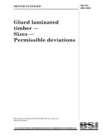
1 Ventilator
2 Volume measuring device to be tested
3 Resistance
4 Test lung
5 Pressure sensor
6 Recorder p (t) with an accuracy of ±2 % of actual reading for verification of accuracy of volume measuring device
7 Breathing system
8 Expiratory valve
Figure 101 Ð Typical configuration of test apparatus for measurement of expiratory volume
Table 101 Ð Test conditions for expiratory volume tests
Adjustable parameter
Test conditions
Adult use
Tidal volume VT (ml) as measured by means
of pressure sensor on test lung
(VT = C 3 Pmax)
Frequency f (min21)
I/E ratio
Resistance R (kPa/l/s)
Isothermal compliance C (ml/kPa)
500
10
1/2 or nearest
0,5 kPa/l/s ± 10 %
500 ml/kPa ± 5 %
Paediatric use
Neonatal use
300
20
1/2 or nearest
2 kPa/l/s ± 10 %
200 ml/kPa ± 5 %
30
30
1/2 or nearest
5 kPa/l/s ± 10 %
10 ml/kPa ± 5 %
NOTE The accuracies for C and R apply over the ranges of the measured parameters.
BSI 01-1999
Page 14
EN 794-3:1998
51.106 Measuring device for expiratory volume
If a measuring device for the expiratory tidal volume
or minute volume is provided, the accuracy shall be
within ±20 % of actual reading for the range specified
by the manufacturer.
Test by visual inspection and verification of the
accuracy using the apparatus as outlined in Figure 101
and Table 101.
NOTE Location of the volume measuring device in Figure 101 is
arbitrary. It can be located elsewhere in the breathing system.
51.107 R) Breathing system integrity alarm
(disconnection)
If a ventilator breathing system integrity alarm is
provided it shall generate an auditory signal in the case
of disconnection of the patient from the ventilator and
a means for silencing the alarm shall be provided in
accordance with 51.109.
Compliance shall be checked by disconnecting the
patient connection port while performing a controlled
ventilation.
The operational apparatus is attached to a test lung
and operated in accordance with the instructions for
use. The auditory alarm signal shall sound within 20 s
following disconnection. In the case of IMV it is
permissible to delay the alarm for the period between
two IMV strokes but not longer than 45 s.
51.108 Oxygen monitor and alarms
If the ventilator is fitted with an oxygen monitor for
measurement of the inspiratory oxygen concentration,
it shall be in compliance with prEN 12598:1996 and
shall have a low-concentration auditory alarm.
Compliance shall be tested by visual inspection and
functional testing by simulating an oxygen
concentration below the set alarm limit.
51.109 Alarms
Electrically generated visual alarms, if provided, shall
comply with EN 475. If visual alarms are generated by
other means, e.g. pneumatically, they shall comply with
the colours specified in EN 475.
51.109.1 The characteristics of any auditory alarm
shall be disclosed by the manufacturer.
NOTE The auditory level characteristics should be appropriate
for the intended application(s), e.g. in a road ambulance, between
the departments of a hospital, in a helicopter, etc.
51.109.2 The maximum time for which an auditory
alarm signal can be silenced shall be 120 s.
51.109.3 If an auditory alarm signal(s) can be disabled
by the operator there shall be a visual indication that it
has been disabled.
51.109.4 If adjustable alarms are provided they shall
be indicated continuously or on operator demand.
51.110 Protection against inadvertent
adjustments
Means of protection shall be provided against
inadvertent adjustment of controls which can create a
hazardous output.
NOTE Mechanical techniques such as locks, shielding,
friction-loading and detents are considered suitable.
For pressure-sensitive finger pads, capacitive finger switches and
microprocessor oriented ªsoftº controls, a specific sequence of
key or switch operations is considered suitable.
Test for compliance by visual inspection following the
instructions for use.
Section nine: Abnormal operation and
fault conditions; environmental tests
52 Abnormal operation and fault
conditions
Clause 52 of EN 60601-1:1990 applies.
53 Environmental tests
Clause 53 of EN 60601-1:1990 applies.
Section ten: Constructional requirements
54 General
Clause 54 of EN 60601-1:1990 applies together with the
following modification and addition:
54.1 Arrangements of functions
Replace 54.1 with the following:
R) A single fault condition shall not cause a
monitoring and/or alarm device, as specified in
clause 51, and the corresponding ventilation control
function to fail in such a way that the monitoring
function becomes simultaneously ineffective, and thus
fails to detect the loss of the monitored ventilator
function.
Test for compliance by simulation of a single fault
condition and/or visual inspection.
54.101 R) Leaching of substances
All parts of the ventilator shall be designed and
manufactured to minimize health risks due to
substances leached or leaking from the device during
use.
Documentary evidence shall be held by the
manufacturer.
54.102 Delivered oxygen concentration
The ventilator shall be capable of delivering at least
95 % O2 (V/V).
54.103 The ventilator, or its carrying case if applicable,
shall be provided with means for lifting and carrying.
55 Enclosures and covers
Clause 55 of EN 60601-1:1990 applies with the
following additions:
55.101 Physical dimensions
55.101.1 Size
The external dimensions of the ventilator shall be
given [see 6.8.2aa), 8th dash].
BSI 01-1999
Page 15
EN 794-3:1998
56 Components and general assembly
Clause 56 of EN 60601-1:1990 applies with the
following additions and modifications:
In 56.3 add the following items:
aa) If more than one high pressure input port is
provided, each port shall be fitted with means to
prevent reverse flow either to the atmosphere or to the
supply system.
The reverse flow of gases from one to another high
pressure input port of the same gas type shall not
exceed 100 ml/min (ATPD) under normal conditions.
The reverse flow of gases from one to another high
pressure input port of a different gas shall not exceed
100 ml/h (ATPD) under normal and single fault
conditions.
Evidence of compliance with these requirements,
either by test or other methods, shall be provided by
the manufacturer.
bb) High pressure gas input port connectors
If the ventilator is intended to be connected to a
medical gas supply system (either a medical gas
pipeline system complying with prEN 737-3:1994 or a
pressure regulator complying with EN 738-1), each high
pressure gas input port connector shall be either the
body of a non-interchangeable screw-threaded (NIST)
connector complying with EN 739 or a probe
complying with EN 737-1 and prEN 737-6:1996. See
annex DD for special national conditions.
cc) Connection to the medical gas supply
system
If a user-detachable hose assembly is provided for
connection between the ventilator and the medical gas
supply system, it shall comply with EN 739. If a hose
assembly is permanently connected to the ventilator,
the connector to the medical gas supply system shall
be a probe complying with EN 737-1.
dd) Ventilator breathing system connectors
Ventilator breathing system connectors, if conical, shall
be 8,5 mm, 15 mm or 22 mm size connectors complying
with EN 1281-1 and EN 1281-2.
Non-conical connectors shall not engage with conical
connectors complying with EN 1281-1 or EN 1281-2
unless they comply with the engagement,
disengagement and leakage requirements of EN 1281-1
or EN 1281-2.
ee) Gas exhaust port connector
If a gas exhaust port connector is provided, it shall be
one of the following:
Ð a 30 mm male conical connector complying with
EN 1281-1; or
Ð a permanent connection or proprietary connector
incompatible with EN 1281-1 and EN 737-1.
BSI 01-1999
ff) Emergency air intake port
An emergency air intake port shall be provided and
shall not accept any connector complying with
EN 1281-1 and EN 1281-2.
NOTE An emergency air intake port should be designed so that it
cannot easily be obstructed when the ventilator is in use.
gg) Patient connection port
The patient connection port connector, if conical, shall
be either 8,5 mm female or coaxial 15 mm/22 mm
complying with EN 1281-1 and EN 1281-2.
hh) Manual ventilation port
If a manual ventilation port is provided, the connector
shall be either 22 mm conical female complying with
EN 1281-1 or male cylindrical connector that will
accept a breathing tube complying with
prEN 12342:1996.
ii) Flow direction-sensitive component
connectors
Any flow direction-sensitive, operator-detachable
component shall be so designed that it cannot be fitted
in such a way as to present a hazard to the patient.
jj) Accessory port
If an accessory port is provided, it shall not be
compatible with connectors as specified in EN 1281-1
or EN 1281-2 and shall be provided with a means to
secure engagement and closure.
NOTE This port is generally used for sampling of gases or for the
introduction of therapeutic aerosols.
kk) Monitoring probe port
If a port is provided for the introduction of a
monitoring probe, it shall not be compatible with
connectors complying with EN 1281-1 or EN 1281-2 and
shall be provided with a means to secure the probe in
position and a means to secure closure after removal
of the probe.
In clause 56 add the following:
56.101 Reservoir bags and breathing tubes
56.101.1 Any reservoir bags intended for use in the
ventilator breathing system shall comply with EN 1820.
Breathing tubes with an internal diameter of more than
18 mm, intended for use in the ventilator breathing
system, shall comply with prEN 12342:1996.
56.101.2 Respiratory gas-conducting
components (packaging and decontamination)
56.101.2.1 If a claim is made in the labelling that a
device is sterile it shall have been sterilized using an
appropriate, validated method as specified in EN 550,
EN 552, EN 554 and EN 556.
Page 16
EN 794-3:1998
56.101.2.2 Non-sterile device packaging systems shall
be designed to maintain products which are intended
to be sterilized before use at their intended level of
cleanliness and shall be designed to minimize the risk
of microbial contamination.
Evidence about the method(s) used to ensure the
intended level of cleanliness of breathing system
components during production and supply shall be
given by the manufacturer upon request.
56.101.2.3 Device packaging and/or labelling shall
differentiate between the same or similar products
placed on the market, both sterile and non-sterile.
56.101.2.4 All parts of the ventilator which are subject
to contamination by exhaled gases during any form of
ventilation and are intended to be reused, shall be
disinfectable or sterilizable.
56.102 Humidifiers and heat and moisture
exchangers
Any humidifier or heat and moisture exchanger either
incorporated into the ventilator or recommended by
the manufacturer for use with the ventilator shall
comply with prEN ISO 8185:1995 and ISO 9360
respectively.
56.103 Inspiratory and expiratory resistances
The inspiratory and expiratory resistance measured at
the patient connection port shall, during spontaneous
breathing and normal operation, not exceed 0.6 kPa
(6 cm H2O) at 60 l/min for adult use, 30 l/min for
paediatric use and 5 l/min for neonatal use.
Compliance shall be checked by measurement of the
pressure at the patient connection port at the specified
flows.
56.104 Leakage from the complete ventilator
breathing system
Leakage from the ventilator breathing system shall not
exceed 200 ml/min for adult breathing systems,
100 ml/min for paediatric breathing systems or
50 ml/min for neonatal breathing systems.
Compliance shall be determined by the following test:
Set up the breathing system for the intended
application as recommended by the manufacturer. Seal
all ports. Connect the pressure measuring device and
introduce air into the breathing system until a pressure
of 2 kPa is reached for neonatal breathing systems,
4 kPa for paediatric breathing systems or 5 kPa for
adult breathing systems Adjust the flow of air to
stabilize the pressure and record the leakage flow.
56.105 Tests for compliance
Compliance with 56.3 and 56.101 to 56.104 shall be
checked by visual inspection and functional tests,
simulating the conditions specified.
57 Mains parts, components and layout
Clause 57 of EN 60601-1:1990 applies together with the
following additions:
In 57.3a) add the following:
R) Any supply cord of an electrically powered
ventilator shall be a non-detachable cord or shall be
protected against accidental disconnection from the
ventilator.
Compliance shall be checked by inspection and the
test described in EN 60601-1:1990, 57.4 respectively.
During the test, the mains connector shall not become
disconnected from the appliance inlet.
58 Protective earthing Ð Terminals and
connections
Clause 58 of EN 60601-1:1990 applies.
59 Construction and layout
Clause 59 of EN 60601-1:1990 applies.
BSI 01-1999
Page 17
EN 794-3:1998
Annexes
Annexes A to K of EN 60601-1:1990 apply.
Annex AA (informative)
Rationale
This annex provides a concise rationale for the
important requirements of this European Standard and
is intended for those who are familiar with the subject
of this European Standard but who have not
participated in its development. An understanding of
the reasons for the main requirements is considered to
be essential for its proper application.
Furthermore, as clinical practice and technology
change, it is believed that a rationale for the present
requirements will facilitate any revision of this
European Standard necessitated by those
developments.
The clauses in this annex have been so numbered to
correspond to the clauses in this European Standard to
which they refer. The numbering is, therefore, not
consecutive.
AA.1 The purpose of this European Standard is to
establish particular requirements for the safety of
emergency and transport ventilators.
Emergency and transport ventilators are often installed
in ambulances or other types of rescue equipment, but
are also often used outside of them, where they have
to be carried by the operator to other persons. It also
has to be considered that the operators could have
limited training.
AA 1.101 Current Federal Aviation Requirements/Joint
Aviation Requirements (FAR/JAR) regulations and
EU regulations are likely to impose requirements on
these ventilators.
AA.3 The definition of ªapplied partº in this European
Standard is the basis for clarification of requirements
for, and measurement of, patient leakage current.
It cannot be excluded that antistatic tubing or other
tubing which is considered as electrically conductive
may be used in the breathing system of ventilators.
Parts integrated with ventilators, such as temperature
and carbon dioxide sensors, which are intended to
come into contact with the patient and which are
electrically connected to the ventilator are considered
as parts for which requirements for leakage currents
can be specified in this European Standard. Such parts
are therefore included in the definition of the applied
part.
AA.4.1[3.6aa), 2nd dash] This requirement, however,
is equivalent to EN 60601-1:1990, 3.1 which effectively
states that all devices shall cause no safety hazard
under normal conditions and a single fault condition.
BSI 01-1999
It is therefore not only logical but also prudent to
handle a software programme error as a single fault
condition in order amply to accommodate software
driven devices within the framework of
EN 60601-1:1990. This approach is advisable, especially
with respect to, e.g. a failure mode effect analysis, to
prove compliance with EN 60601-1:1990, 3.1.
AA.4.1[3.6bb)] A fault condition which is not
detected can exist for a long time. Under those
circumstances it is not acceptable to regard a further
fault as a second which can be disregarded. Such a
first fault is to be regarded as a normal condition.
AA.6.8.2aa), 1st dash The available operating time
may vary but provides the most important information
for a ventilator mostly used outside of a hospital,
where no extra power backup is available
(see 51.101.1).
AA.6.8.2d) Wrongly assembling a ventilator so that it
causes incorrect operation or complete malfunction is
a serious hazard which can result in inadequate
ventilation of the patient.
AA.6.8.3 No mention of patient parameter or machine
parameter is given here because this distinction exists
in EN 60601-1:1990.
Examples of machine parameters are ªstroke volumeº
rather than ªtidal volumeº, ªgenerated pressureº rather
than ªairway pressureº, ªset ventilationº rather than
ªexpired ventilationº, ªreturn-port pressureº rather than
ªairway pressureº. In this last instance, it is especially
important to distinguish between these in some
neonatal ventilators.
Some fault conditions, e.g. obstruction or leaks, can
cause serious differences between volumes and
pressures in the ventilator and the corresponding
volumes and pressures in the patient; other fault
conditions, e.g. excessive secretions or the
accumulation of condensation in a pressure line, can
cause serious errors in directly measured patient
parameters.
AA.6.8.3, 2nd dash, 6th bullet Some changes in the
condition and composition of the gas at the sensor can
alter the flow ± or volume ± sensitivity for some types
of sensor. Also, changes in the conditions in the sensor
may alter the correction required to express the flow,
volume or ventilation under some standard conditions.
For example, a volume-displacement-type meter,
whenever it is operating normally, will indicate the
volume which has passed through it, expressed in
terms of the conditions within it, irrespective of those
conditions or of the composition of the gas. However,
if a pneumotachograph sensor at the gas return port is
used to drive a display of ªexpired tidal volumeº
expressed at BTPS on the assumption that typical
expired air is saturated at 30 8C, the indication will be
less than the true expired volume at BTPS.
Page 18
EN 794-3:1998
AA.6.8.3, 2nd dash, 14th bullet A zero error
together with a sensitivity error is needed if a variable
can pass through zero, or can, in any application, cover
a range such that the minimum is a small fraction of
the maximum.
AA.10.2.1 The ranges of environmental conditions
specified do not cover the extremes that can be
experienced in certain severe environments but have
been chosen to represent normal use conditions. The
manufacturer's declaration required by 6.8.3e) is
intended to allow users to select devices appropriate
for use in different operating environments.
AA.10.2.2aa) The electrical power tolerances
specified are more severe than those normally used for
medical devices, but this is to allow for the fact that
emergency devices will often be required to operate
from small portable generators, DC to DC converters,
battery systems subjected to simultaneous charging
and other such poorly regulated power sources.
AA.19.4 h).101 See the rationale to 3.
AA.21.101 There are no established generalized test
programmes that exactly reproduce the range of
vibration and shock conditions that devices might meet
when installed in a range of land vehicles and aircraft.
The dynamic tests specified in this clause have been
chosen on the basis that devices tested to these levels
are likely to withstand the normal dynamic
disturbances that they will meet when used in the
range of vehicles and aircraft (including helicopters)
likely to be used for carrying ventilated patients.
AA.43 Reports of fire caused by medical devices are
unusual. However, when such fires occur in the
hospital environment they can have tragic
consequences.
The risk of a fire is fundamentally determined by the
three elements which are necessary in order to start a
fire:
Ð ignitable material (fuel);
Ð temperature equal to or above the minimum
ignition temperature of the material, or sparks with
energy dissipation equal to or above the minimum
ignition energy of the materials;
Ðan oxidant.
Therefore, following the basic safety concepts of
EN 60601-1:1990, the objective in the design of the
equipment is to ensure that under both normal and
single fault conditions and under the oxidising
conditions to which the material may be exposed, the
temperature of any material is not raised to its
minimum ignition temperature or the spark energy
does not exceed the material ignition energy level.
Alternatively, contained ignition may occur provided it
is self limiting so that no hazard is created, e.g., a fuse
or a resistor within a sealed compartment.
Minimum ignition temperatures for a large number of
specific materials are well established in published
literature, although usually only for ambient air and
pure oxygen environments. The minimum ignition
temperature may be critically dependent upon the
concentration of oxidant present. If ignition
temperatures for other materials or different oxygen
concentrations are required these can be determined
using the methods and apparatus described in
IEC 60079-4.
In considering the ignitable materials, particular
attention should be paid to materials which may
accumulate during prolonged use, e.g. airborne
particles of paper or cotton.
The risk of fire directly caused by sparking of
electrical circuits is generally considered insignificant
in medical equipment as temperature rise resulting
from the power dissipation caused by a spark will not
normally reach the ignition temperature of the solid
materials generally used when following good design
practice.
However, if materials with a low ignition temperature
and a very low thermal capacity, e.g. cotton wool,
paper or organic fibre accumulations, are present then
it may not be possible to determine the surface
temperatures attained during exposure to spark energy
and specific tests, e.g. ignition tests, may be necessary
to assure safety under these conditions.
In certain standards currently in use the requirements
to minimise fire risk are based on limitation of
temperature, electrical energy and oxidant
concentration to absolute values. The temperature
value is based on the minimum hotplate ignition
temperature for fire retardant cotton in 100 % oxygen
which is given in the American NFPA publication 53 M
as 310 8C. The assumption was therefore made that
300 8C was an acceptable temperature limit in medical
equipment with oxygen enriched atmospheres.
The origin of the electrical energy values which have
been used is less clear and it would seem that, in the
absence of specific controlled tests, figures have been
adopted from accepted working practices or from tests
performed in other environments. However, simple
tests and detailed analysis of the known factors
involved in causing an oxygen fire show that these
figures can be either over-restrictive or potentially
hazardous depending, in particular, on the manner in
which the power may be dissipated and the proximity
and type of any ªfuelº present.
It is now generally accepted that there are no single or
universally applicable ranges of temperature, energy
and concentration of oxidant which can ensure safety
under all circumstances. Ultimately, electrical energy is
only significant in respect of its ability to raise the
temperature of ignitable materials and this in turn
depends upon the particular configuration and the
proximity of any ignitable materials.
BSI 01-1999